Table of Contents
Advertisement
Quick Links
Instruction Manual
Form 5874
December 2014
Type MR105 Direct-Operated Pressure
Reducing Regulators
Contents
Introduction .................................................................. 2
Specifications .............................................................. 2
Principle of Operation .................................................. 3
Installation ................................................................... 4
Overpressure Protection.............................................. 8
Startup ......................................................................... 8
Adjustment................................................................... 9
Shutdown..................................................................... 9
Maintenance .............................................................. 10
Parts List.................................................................... 16
!
Failure to follow these instructions or
to properly install and maintain this
equipment could result in an explosion,
fi re and/or chemical contamination
causing property damage and personal
injury or death.
Fisher
regulators must be installed,
®
operated and maintained in
accordance with federal, state and
local codes, rules and regulations
and Emerson Process Management
Regulator Technologies, Inc.
(Emerson™) instructions.
If the regulator vents gas or a leak
develops in the system, service to the unit
may be required. Failure to correct trouble
could result in a hazardous condition.
Installation, operation and maintenance
procedures performed by unqualifi ed
personnel may result in improper
P1204
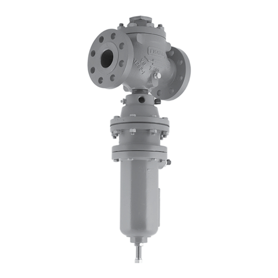
TYPE MR105 WITH
HIgH-PRESSURE ACTUATOR
Figure 1. Type MR105 Direct-Operated Pressure
adjustment and unsafe operation. Either
condition may result in equipment damage
or personal injury. Call a qualifi ed
personnel when installing, operating and
maintaining the Type MR105 regulator.
www.fisherregulators.com
Type MR105
P1205
TYPE MR105 WITH
LOW-PRESSURE ACTUATOR
Reducing Regulators
Advertisement
Table of Contents

Related Manuals for Emerson MR105


Summary of Contents for Emerson MR105
-
Page 1: Table Of Contents
LOW-PRESSURE ACTUATOR and Emerson Process Management Regulator Technologies, Inc. Figure 1. Type MR105 Direct-Operated Pressure Reducing Regulators (Emerson™) instructions. If the regulator vents gas or a leak develops in the system, service to the unit may be required. -
Page 2: Introduction
Type MR105 Specifications The Specifications section on this page provides the ratings and other specifications for the Type MR105. The following information is stamped on the nameplate fastened on the regulator at the factory: type; body size; maximum inlet, outlet and differential pressure; maximum pressure above setpoint; maximum casing pressure;... -
Page 3: Principle Of Operation
Also, the bleed valve option allows you to purge the air trapped underneath the diaphragm The Type MR105 is a direct-operated pressure when the high-pressure regulator is installed in the upright reducing regulator. Downstream pressure is registered position. -
Page 4: Installation
M1178 INLET PRESSURE OUTLET PRESSURE ATMOSPHERIC PRESSURE Figure 2. Type MR105 with Low-Pressure Actuator Operational Schematic downstream as the regulator opens in response to the Protection section for recommendations decreased pressure underneath the diaphragm. The on how to prevent service conditions downward motion of the plug allows flow through the from exceeding those limits. - Page 5 CONTROL SPRINg SPRINg CASE VENT M1181 INLET PRESSURE OUTLET PRESSURE ATMOSPHERIC PRESSURE Figure 3. Type MR105 with High-Pressure Actuator Operational Schematic Table 3. Maximum Inlet, Outlet and Emergency Casing Pressure MAxIMUM OUTLET PRESSURE MAxIMUM EMERgENCY CASINg PRESSURE MAxIMUM INLET BODY...
- Page 6 Before installing the regulator: • Check for damage which might have occurred during shipment. Figure 4. Type MR105 with High-Pressure Actuator • Check for and remove any dirt or foreign material and Restrictor Option which may have accumulated in the regulator body.
- Page 7 • Do not install the Type MR105 in a location where there can be excessive water Regulators Subjected to Heavy accumulation or ice formation, such as directly...
-
Page 8: Overpressure Protection
Common methods of Type MR105 regulators have a 1/2 NPT vent opening on external overpressure protection include relief valves, the spring case. When installed inside a building or if it is... -
Page 9: Adjustment
Adjustment procedure. Figure 5. Type MR105 with High Pressure Actuator, Drain Valve and Bleed Valve Option 5. If resetting setpoint, then set the regulator to the desired outlet pressure according to the Adjustment procedure. -
Page 10: Maintenance
Annual Maintenance case pressure prior to outlet pressure. 4. If the actuator is pressure loaded, vent the The stem O-rings on the Type MR105 actuator can be loading pressure slowly to release pressure in the lubricated during regularly scheduled maintenance, spring case. - Page 11 Replacing Trim Parts position. Refer to Table 6 for torque specifications. Refer to Figure 6 while servicing Type MR105 regulators. Perform this procedure when inspecting, cleaning or replacing individual trim package parts.
- Page 12 Type MR105 1. Remove the lower indicator fitting (key 5) 8. Remove the upside-down body flange (key 2) if and attached parts. Proceed to step 5 if only it was anchored on the body (key 1). Coat the maintenance on the indicator fitting or attached cage seating surfaces of the valve body web parts is performed.
- Page 13 Type MR105 Actuator Maintenance 6. Unscrew the jam nuts (key 48) and remove them from the actuator stem (key 40). Perform this procedure if it is desired to inspect or 7. Remove the Belleville spring washer (key 49), replace the diaphragm or other internal parts or if it...
- Page 14 Type MR105 alignment. Do not loosen the bonnet thread to align Note the pipe holes. Always tighten the bonnet to make For pressure-loaded actuator option skip alignment for the control line. steps 20 and 21 and proceed to step 22...
- Page 15 Type MR105 11. Remove the wiper ring (key 45, detail Z) on the WARNINg threaded end of the lower diaphragm casing (key 62) to reach the bearing (key 46) and stem Personal injury, equipment damage or O-ring (key 47). Install the new stem O-ring and leakage due to escaping fluid may result bearing and put back the wiper.
-
Page 16: Parts List
Type MR105 16. Place the lower spring seat (key 54) and Belleville WARNINg spring washer (key 49) over the actuator stem (key 40) and on top of the diaphragm (key 56). Personal injury, equipment damage or The raised inner diameter of the spring washer... - Page 17 2. National Lubricating Grease Institute. NPS 4 / DN 100 RMR1058XF42 Ethylene Propylene (EPDM) NPS 1 / DN 25 RMR1058XE12 Figure 6. Type MR105 Direct-Operated Pressure Reducing NPS 2 / DN 50 RMR1058XE22 Regulator Assemblies NPS 3 / DN 80 RMR1058XE32...
- Page 18 Type MR105 Key 1, Type MR105 Valve Bodies PART NUMBER MATERIAL END CONNECTION NPS 1 / dN 25 NPS 2 / dN 50 NPS 3 / dN 80 NPS 4 / dN 100 34B7611X012 38A8845X012 - - - - - - - - - - -...
- Page 19 Vent Assembly (NACE) (2 required/ NPS 4 / DN 100 24A5644X052 1 required for Pressure-Loaded Actuator) Type Y602-12 16* Valve Plug Plug (Type MR105 Without Travel Indicator Only) 416 Stainless Steel Steel NPS 1 / DN 25 14A6780X012 NPS 1 / DN 25...
- Page 20 Type MR105 Description Part Number Description Part Number Lower Spring Guide, Zinc-Plated Steel (NACE) Cap Screw (10 required) (Low-Pressure Actuator only) GE39171X012 (Low-Pressure Actuator only) Lower Diaphragm Head Steel 1A368424052 17-4 Stainless Steel (NACE) Stainless Steel (NACE) 1A3684X0102 Low-Pressure Actuator...
- Page 21 S = MULTI-PURPOSE PTFE THREAD SEALANT NoTe: keyS 64 ANd 71 ARe USed oNLy FoR PReSSURe-LoAded ACTUAToRS. 1. Lubricants and sealants must be selected such that they meet the temperature requirements. Figure 6. Type MR105 Direct-Operated Pressure Reducing Regulator Assemblies (continued)
- Page 22 GE38435 APPLY LUBRICANT OR SEALANT L1 = MULTI-PURPOSE PTFE LUBRICANT S = MULTI-PURPOSE PTFE THREAD SEALANT 1. Lubricants and sealants must be selected such that they meet the temperature requirements. Figure 6. Type MR105 Direct-Operated Pressure Reducing Regulator Assemblies (continued)
- Page 23 SEE DETAIL W TYPE MR105 WITH OPTIONAL TRAVEL INDICATOR GE38435 APPLY LUBRICANT L1 = MULTI-PURPOSE PTFE LUBRICANT 1. Lubricants and sealants must be selected such that they meet the temperature requirements. Figure 6. Type MR105 Direct-Operated Pressure Reducing Regulator Assemblies (continued)
- Page 24 For further information visit www.fisherregulators.com The Emerson logo is a trademark and service mark of Emerson Electric Co. All other marks are the property of their prospective owners. Fisher is a mark owned by Fisher Controls International LLC, a business of Emerson Process Management.
Need help?
Do you have a question about the MR105 and is the answer not in the manual?
Questions and answers