Emerson unidrive m300 Quick Start Manual
Frame sizes 1 to 4
Hide thumbs
Also See for unidrive m300:
- User manual (198 pages) ,
- Installation manual (120 pages) ,
- Quick start manual (58 pages)

Related Manuals for Emerson unidrive m300


Summary of Contents for Emerson unidrive m300
- Page 1 Quick Start Guide Unidrive M300 Frame sizes 1 to 4 Enhance throughput with Machine Safety Part Number: 0478-0039-05 Issue: 5...
- Page 2 This guide is intended to provide basic information required in order to set-up a drive to run a motor. For more detailed installation information, please refer to the Unidrive M300 User Guide which is available to download from: www.controltechniques.com/userguides or www.emersonindustrial.com/en-EN/leroy-somer-motors- drives/downloads/Pages/manuals.aspx...
-
Page 3: Table Of Contents
4 ................. 33 Motor overload protection ..................33 Motor overspeed protection ................... 33 9.10 Thermal memory retention ..................33 9.11 Group installation ....................34 9.12 UL listed accessories ..................... 34 Unidrive M300 Quick Start Guide Issue Number: 5... - Page 4 <16 A EN 61000-3-2:2006 Applicable where input current <16 A. No limits apply for professional equipment where input power >1 kW. Unidrive M300 Quick Start Guide Issue Number: 5...
- Page 5 EC type-examination has been carried out by the following notified body: TÜV Rheinland Industrie Service GmbH Alboinstraße 56 12103 Berlin, Germany Notified Body identification number: 0035 EC type-examination certificate number: 01/205/5383.00/14 and 01/205/5387.00/14 Unidrive M300 Quick Start Guide Issue Number: 5...
- Page 6 EMC. The assembler is responsible for ensuring that the end product or system complies with all the relevant laws in the country where it is to be used. Refer to the User Guide. Unidrive M300 Quick Start Guide Issue Number: 5...
-
Page 7: Product Information
04400135 16.3 13.5 04400170 20.7 The nominal cable sizes shown in the table above, are provided as a guide only. Ensure NOTE that the cables used conform to the local wiring regulations. Unidrive M300 Quick Start Guide Issue Number: 4... -
Page 8: Options
Type Option module Color Name Further details Purple SI-PROFIBUS Medium SI-DeviceNet Grey Light Grey SI-CANopen Fieldbus See relevant option module User Guide Beige SI-Ethernet Brown Red SI-EtherCAT Automation Orange SI-I/O (I/O expansion) Unidrive M300 Quick Start Guide Issue Number: 4... -
Page 9: Mechanical Installation
130 5.12 143 5.70 2.08 8.07 3.07 150 5.91 194 7.63 2.17 0.00 0.00 3.93 8.90 3.54 160 6.30 215 8.46 70.7 2.80 277 10.91 115 4.53 175 6.89 265 10.43 3.40 0.23 Unidrive M300 Quick Start Guide Issue Number: 4... - Page 10 5. Control connections 6. Braking terminal 7. Internal EMC filter screw 8. DC bus + 9. DC bus - 10. Motor connections 11. AC supply connections 12. Ground connections 13. SAFE TORQUE OFF connections Unidrive M300 Quick Start Guide Issue Number: 4...
-
Page 11: Electrical Installation
40 °C (104 °F) Table 4-1 Braking resistor resistance and power rating (100 V) Minimum Instantaneous Continuous Model resistance* power rating power rating Ω 01100017 0.25 01100024 0.37 02100042 0.75 02100056 Unidrive M300 Quick Start Guide Issue Number: 4... -
Page 12: Ground Leakage
9.36 mA* AC at 110 V, 50 Hz (2 phase, line to line supply, star point ground) 16.4 mA* AC at 110 V, 50 Hz (1 phase, line to neutral supply, star point ground) 5.3 mA* AC at 230 V, 50 Hz (3 phase supply, star point ground) Unidrive M300 Quick Start Guide Issue Number: 4... - Page 13 Type A can only be used with single phase drives • Type B must be used with three phase drives Only type B ELCB / RCD are suitable for use with 3 phase inverter drives. WARNING Unidrive M300 Quick Start Guide Issue Number: 4...
-
Page 14: Control Terminal Configurations And Wiring
Action will only occur if the drive is inactive, not in UU state and no User Actions are running. Otherwise, the parameter will return to its pre altered value on exit from edit mode. All parameters are saved if this parameter changes. Unidrive M300 Quick Start Guide Issue Number: 4... - Page 15 + 10 V output Voltage speed reference input (AI 2) Analog output 1 (motor frequency) + 24 V output Digital output (zero frequency) Unassigned Run forward Run reverse Analog input 1/ input 2 select Unidrive M300 Quick Start Guide Issue Number: 4...
- Page 16 Reference selected Terminal 5 Terminal 14 Run forward Analog reference 1 ( 01.036 Preset speed 2 ( 01.022 Run reverse Preset speed 3 ( 01.023 Preset speed 4 ( 01.024 Reference select Unidrive M300 Quick Start Guide Issue Number: 4...
- Page 17 (AI 2) Analog output 1 (motor frequency) + 24 V output Digital output (zero frequency) Unassigned Run forward Run reverse Analog input 1/ input 2 select Unidrive M300 Quick Start Guide Issue Number: 4...
- Page 18 3 = last value at power-up and only (zero frequency) change when drive is running, Unassigned 4 = zero at power-up and drive disabled, only change when drive is Run forward running. Run reverse 14 UP Unidrive M300 Quick Start Guide Issue Number: 4...
- Page 19 Pr 14.014: PID output lower limit (%) reference input input (AI 2) Analog output 1 (motor frequency) + 24 V output Digital output (zero frequency) Unassigned Run forward Run reverse Pid enable Unidrive M300 Quick Start Guide Issue Number: 4...
-
Page 20: Emc
Equipment which is sensitive to electrical interference operating nearby In this case it is necessary to use: • The optional external EMC filter • A shielded motor cable, with shield clamped to the grounded metal panel Unidrive M300 Quick Start Guide Issue Number: 4... -
Page 21: Safe Torque Off (Sto)
A shielded control cable, with shield clamped to the grounded metal panel Full instructions are given in the Drive User Guide. A full range of external EMC filters are also available for use with Unidrive M300. SAFE TORQUE OFF (STO) The SAFE TORQUE OFF function provides a means for preventing the drive from generating torque in the motor with a very high level of integrity. -
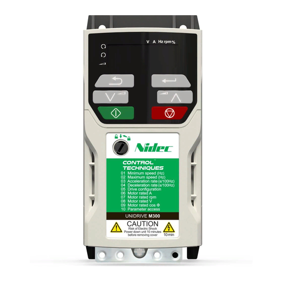
Page 22: Keypad And Display
Figure 5-1 Unidrive M300 keypad detail (1) The Enter button is used to enter parameter view or edit mode, or to accept a parameter edit. -
Page 23: Saving Parameters
2. Select 'Def.50’ or 'Def.60' in Pr mm.000. (alternatively, enter 1233 (50 Hz settings) or 1244 (60 Hz settings) in Pr mm.000). 3. Either: • Press the red reset button • Carry out a drive reset through serial communications by setting Pr 10.038 to 100 Unidrive M300 Quick Start Guide Issue Number: 4... -
Page 24: Basic Parameters (Menu 0)
0.00 Hz RW Num REF Hz 00.025 User Security Code 0 to 9999 RW Num ND NC PT Power-up Keypad 00.027 Reset (0), Last (1), Preset (2) Reset (0) Control Mode Reference Unidrive M300 Quick Start Guide Issue Number: 4... - Page 25 0.00 to 20.00 Hz 2.00 Hz RW Num Frequency 00.050 BC Brake Delay 0.0 to 25.0 s 1.00 s RW Num BC Post-brake Release 00.051 0.0 to 25.0 s 1.00 s RW Num Delay Unidrive M300 Quick Start Guide Issue Number: 4...
- Page 26 * If this parameter is read via serial communications, it will show pole pairs. Read / Read Number Binary Text string Filtered Write only parameter parameter parameter Protected Rating Power-down default User save DE Destination copied parameter dependent save value Unidrive M300 Quick Start Guide Issue Number: 4...
- Page 27 Unidrive M300 Quick Start Guide Issue Number: 4...
- Page 28 Preset 00.018 Reference 1 AV.Pr AI.Pr Pad.Ref Keypad reference E. Pot Input Read-write (RW) 00.XXX terminals parameter Read-only (RO) Output 00.XXX parameter terminals The parameters are all shown in their default settings Unidrive M300 Quick Start Guide Issue Number: 4...
- Page 29 Motor Voltage Boost Speed 00.032 Dynamic V/f Select Motor Rpm 05.004 Power stage Maximum Switching 00.037 Frequency 05.001 Output Frequency RFC-A Current Torque Magnitude 04.002 04.001 Producing Current Magnetising Current Resistor optional Unidrive M300 Quick Start Guide Issue Number: 4...
-
Page 30: Running The Motor
To stop the motor under ramp control, open either the run forward or Stopping run reverse terminal. If the enable terminal is opened while the motor is running, the motor will coast to a stop. Unidrive M300 Quick Start Guide Issue Number: 4... -
Page 31: Nv Media Card Operation
Drive User Guide for further information. The card should not be removed during data transfer, as the drive will produce a trip. If this occurs then either the transfer should be reattempted or in the case of a card to drive transfer, default parameters should be loaded. Unidrive M300 Quick Start Guide Issue Number: 4... -
Page 32: Ul Listing Information
If the drive control stage is powered from an external power supply (+24 V), the power supply must be listed or recognized to UL class 2 with appropriate fusing. • Ground connections must use UL listed closed loop (ring) terminals. Unidrive M300 Quick Start Guide Issue Number: 4... -
Page 33: Cul Requirements For Frame Size 4
The drive is provided with a means to accept and act upon a signal from a thermal sensor or switch imbedded in the motor or from an external protective relay. Refer to the Drive User Guide for further information. Unidrive M300 Quick Start Guide Issue Number: 4... -
Page 34: Group Installation
The following options are UL listed: • AI-485 Adaptor • AI-Backup Adaptor • Remote Keypad • UL Type 1 kit • NV Media card • SI-PROFIBUS • SI-DeviceNet • SI-CANopen • SI-EtherNet • SI-EtherCAT • SI-I/O Unidrive M300 Quick Start Guide Issue Number: 4... - Page 36 Digital I/O Analog I/O 24 V user Analog input 1+ Digital I/O1 Frequency Zero frequency reference 1 10 V user Digital Input 2 Digital input 3 Analog input 2 Frequency Run forward reference 2 Digital input 4 Analog output 1 Run reverse Frequency output Analog input 1/...
Need help?
Do you have a question about the unidrive m300 and is the answer not in the manual?
Questions and answers