
Related Manuals for Emerson HVAC Drive H300


Summary of Contents for Emerson HVAC Drive H300
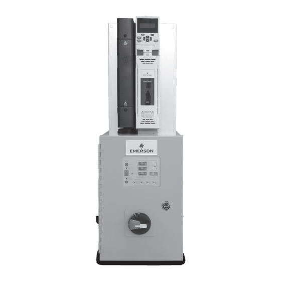
- Page 1 Installation and Commissioning Guide Electronic Bypass Controller HVAC Drive H300, Unidrive M200 and Unidrive M400 Part Number: PSD-H300BP-ICG Issue: 4.1...
-
Page 2: Table Of Contents
Contents Section 1 - Introduction ..................5 Section 2 - Installation Instructions ..............6 2.1 Receiving ......................6 2.2 Nameplate Information ................6 VFD Labels ....................7 Typical Standard VFD Rating Label ............7 Typical VFD Approvals Label ..............7 2.3 Part Number Identification ................8 2.4 Mounting &... - Page 3 Section 4 – Overview of the electronic bypass ..........22 4.1 Control Board .....................22 4.2 Electronic Bypass Keypad Function Summary ..........22 Electronic Bypass Control Functions ............23 4.3 Using the Electronic Bypass Configuration Switches ........24 4.4 Using the Additional Customer Inputs ............25 4.5 Motor Overload ..................26 4.6 Failure and Power Off Conditions ..............26 4.7 Control Modes of the Electronic Bypass ............26...
- Page 4 1. Read this manual in its entirety before installing or operating the electronic bypass package. This manual applies to electronic bypass packages with the Emerson Control Techniques HVAC Drive H300, Unidrive M200 or Unidrive M400 variable frequency drives, and control board part number 1067144-01 and is not intended to be used with any other products.
-
Page 5: Section 1 - Introduction
Thank you for purchasing your Emerson Control Techniques electronic bypass package. This manual provides information concerning the installation, wiring and general startup procedures for both the HVAC Drive H300, Unidrive M200 and Unidrive M400 lines of electronic bypass packages. The electronic bypass is... -
Page 6: Section 2 - Installation Instructions
3 Check the unit for physical damage which may have occurred during shipping. If any part of the package is missing or damaged, notify the carrier and your Emerson Control Techniques representative immediately. 3 Verify that all internal hardware (i.e. components, screws, etc.) is properly seated and fastened securely. -
Page 7: Vfd Labels
VFD Labels Typical Standard VFD Rating Label Frame Current rating size Model Refer to Frame H300-084 01840 A Current rating User Guide size Model Voltage Drive format Refer to H300-084 01840 A User Guide Normal Duty Input Key to approvals Customer and power rating frequency... -
Page 8: Part Number Identification
8 = 8 kW Unidrive M200 and Commander HSK includes LED M = SM-I/O-32 9 = 9 kW keypad as standard. HVAC Drive H300 and Affinity [3] - [6] Horsepower Rating N = SM-I/O-LITE A = 10 kW BA includes LCD keypad as standard. Choose these... -
Page 9: Mounting & Clearances
2.4 Mounting & Clearances Install the electronic bypass package on a vertical surface and allow the following minimum clearances for normal heat dissipation. 12 in Industrial Automation Industrial Automation 6 in 12 in 6 in WARNING WARNING WARNING WARNING Potentially hazardous voltage Potentially hazardous voltage can exist within this device. -
Page 10: Wiring And Precautions
2.5 Wiring and Precautions 2.5.1 General 1. DO NOT connect or disconnect wiring or perform signal checks while the power supply is turned ON. 2. Connect the power supply wiring to the electronic bypass input terminals L1, L2 and L3 on the main circuit disconnect device. 3. -
Page 11: Output Wiring
Connect the main power supply, motor and control wiring using the following recommended conduit locations. The input phase sequence does not affect the output phase sequence of the VFD. It will affect bypass sequence and motor rotation direction. Recommended conduit entrance control wire Industrial Automation WARNING... -
Page 12: Control Circuit Wiring
2.5.4 Control Circuit Wiring 2.5.4.1 Analog Output A 0-10 Vdc analog output signal is available by connecting to Unidrive M200/M400 control terminals 7 (+) and 1 (-) or H300 control terminals 7 (+) and 9 (-). The default is output frequency. 2.5.4.2 Digital Input The electronic bypass combines digital inputs from the H300 inverter and the electronic bypass control board to allow maximum flexibility. -
Page 13: Internal Control Wire Connections
2.5.5.4 Internal Control Wire Connections There are factory connections between the electronic bypass control board and the H300 inverter. These connections are made at the factory and are for reference only. DO NOT change this wiring as it will cause the electronic bypass to operate improperly or not at all. -
Page 14: Inspection
2.6 Inspection Once all wiring is complete, verify that: 1. All wiring is installed. 2. Excess screws, metal filings and wire clippings are removed from inside the unit(s). 3. Screws and fasteners are securely tightened. 4. Exposed wiring has no contact with other wiring or terminals. 2.7 Checking Motor Rotation WARNING Before attempting a trial operation of the electronic bypass package, ensure that the... -
Page 15: Check #2: Rotation On Bypass Power
2.7.2 Check #2: Rotation on Bypass power NOTE: This operation will start the motor across the line. Place the electronic bypass in the Bypass Mode by pressing the BYPASS pushbutton on the electronic bypass keypad. The BYPASS LED will light. Press the HAND button on the electronic bypass keypad. -
Page 16: Section 3 - Operation
Section 3 - Operation WARNING Precautions: 1. Motor rotation MUST be checked in both VFD and Bypass Modes. Failure to confirm rotation may cause severe damage to the electronic bypass, motor or its driven equipment. 2. Only turn ON the input power supply after closing the front door. 3. -
Page 17: Vfd Keypad
The keypad on the VFD is primarily used for speed control in Hand Mode and monitoring purposes as limited programming is required to operate the electronic bypass. See the “HVAC Drive H300 Installation & Commissioning Guide”, “Unidrive M200/M201 User Guide” or the “Unidrive M400 User Guide” for detailed programming information. -
Page 18: System Status Leds
Incoming 1 Select Operation Mode 2 Select Run Mode Power TEST HAND Power On Input AUTO Contactor BYPASS Bypass RESET Contactor Press OFF/RESET once to cancel RUN mode Output Press OFF/RESET twice to cancel OPERATION mode Contactor Alarm Display Motor (1) External Fire Overload... -
Page 19: Test / Vfd / Bypass Buttons
3.1.6 TEST / VFD / BYPASS Buttons There are three (3) buttons used to select the three modes of operation available: 1. Test Mode – Energizes the VFD input contactor only 2. VFD Mode – Energizes the VFD input and output contactors 3. - Page 20 Step 2 – Select the start mode by pressing either the HAND or AUTO buttons. Selecting HAND allows an immediate start in VFD or Bypass Mode, whichever was previously selected. The RUN LED will illuminate at this time. Selecting AUTO will illuminate the AUTO LED.
-
Page 21: Ending Operation
3.3 Ending Operation There are two (2) options available for ending operation. 1. Press OFF/RESET button once – Cancels the start mode of operation. 2. Press OFF/RESET button twice – Cancels the operation mode. Incoming 1 Select Operation Mode 2 Select Run Mode Power TEST HAND... -
Page 22: Section 4 - Overview Of The Electronic Bypass
Section 4 – Overview of the electronic bypass All start/stop, safety, and fire alarm inputs are routed to the electronic bypass control board via customer terminal connections. The VFD analog output is directly connected to the VFD control terminals. The electronic bypass control card is factory set to accept a sinking type (dry contact closure) type input. -
Page 23: Electronic Bypass Control Functions
Electronic Bypass Control Functions Type Location Description Signal / Level Rating 120 Vac single phase (neutral) Input Power 120 Vac Single Phase 120 Vac single phase (hot) Input Contactor Contactor Outputs Bypass Contactor Output Contactor Motor Overload Input 24 Vdc upon overload Drive Fault Input 24 Vdc upon fault 24 Vdc Common to VFD... -
Page 24: Using The Electronic Bypass Configuration Switches
4.3 Using the Electronic Bypass Configuration Switches The bypass configuration switches are a group of four switches that are used to tailor the following: Automatic Bypass Fire Alarm Damper Control Fireman’s Override Note: “ON” disables function Switch 1: Enables or disables the automatic bypass function. With switch 1 in the ON position and the electronic bypass package operating in VFD Mode, a VFD fault will cause both the operation and run modes to be canceled (stopping the motor) and the VFD FAULT LED to illuminate in the Alarm Display. -
Page 25: Using The Additional Customer Inputs
“damper feedback” contact closed (TB3-3) within that time to prevent the bypass controller from “faulting” and preventing motor operation. The bypass keypad will annunciate the faulted condition by flashing one or more of the button status LEDs that happened to be on at the time of the fault. The bypass controller can be reset by cycling the customer reset input, which will reset the 120 second timer and retry motor operation. -
Page 26: Motor Overload
Remote bypass input (TB3-1): can be used to override the keypad selections and force the electronic bypass into Bypass Mode from an external contact. Once this signal is removed, the electronic bypass will not return to its previous mode of operation without keypad interaction. -
Page 27: Vfd Mode
To exit the Test Mode, press the OFF/RESET button on the electronic bypass keypad. The VFD input contactor will open and the TEST and INPUT CONTACTOR LEDs will go out. 4.7.2 VFD mode In VFD Mode both the input and output contactors are energized. A Start command must exist before the VFD can operate. -
Page 28: Auto Mode
4.7.5 Auto Mode In the VFD Auto (automatic) mode, a building automation system or other external device is required to supply start/stop and speed reference information to the electronic bypass package. During Auto Mode operation, the electronic bypass keypad remains enabled for stopping, operation mode and bypass selection functions. -
Page 29: Automatic Bypass On Vfd Fault
4.8.2 Automatic Bypass on VFD Fault In the Automatic Bypass on VFD Fault Mode of operation, when the electronic bypass control board senses a VFD fault it will automatically switch the motor to Bypass operation. This function is enabled by DIP switch 1, position 1, placed in the OFF position. -
Page 30: Section 5 - Programming
The Menu “0” Equivalent parameters apply to the H300 only. These settings are pre-programmed from the factory. DO NOT change any of these values unless directed to by Emerson technical support. Note these parameters should be programmed in the sequence shown. -
Page 31: Recommended Programming
5.2 Recommended Programming Following is a list of parameters that should be programmed at the time of start-up. These values are recommendations only, actual settings should be determined by the application requirements, conditions, and the policies of the equipment owners. Refer to the respective drive User Guide for a full parameter list and explanation. -
Page 32: Section 6 - Alarm & Faults
Section 6 - Alarm & Faults There are two different locations a fault or alarm will be displayed: 1. The electronic bypass keypad 2. The VFD keypad 6.1 Electronic Bypass Keypad Alarms and Faults Incoming 1 Select Operation Mode 2 Select Run Mode Power TEST HAND... - Page 33 3. Fire Alarm: Indicates that a Fire condition exists. If fire alarm is set for Purge Mode, the VFD package will operate the motor at full speed. Note: In Purge Mode all external safeties and motor overloads are disabled. The unit will “run to destruction” in this mode. If fire alarm is set for Stop Mode, the VFD package will disable the motor and prevent it from being operated in either VFD or Bypass Mode.
-
Page 34: Section 7 - Additional Information
Section 7 - Additional Information 7.1 Specifications – Electronic Bypass The electronic bypass package features a user friendly application-specific keypad to simplify operation and provide status indication. Approvals: • VFD Section – UL508C • Bypass Section – UL508A Design: • 3 contactor bypass •... -
Page 35: Maintenance & Inspection
Operating conditions: • Altitude: to 3,300 ft, higher with derating • Ambient operating temp: +32 to +104°F (0 to +40˚C) • Storage temp: -40 to +140˚F (-40 to +60˚C) • 95% relative humidity, non-condensing • Input voltage: +10%, -10%; 208, 230 and 460 Vac •... -
Page 36: Start-Up Checklist - Electronic Bypass
Motor rotation MUST be checked in both VFD and Bypass modes. Failure to confirm rotation may cause severe damage to the electronic bypass, motor or its driven equipment. Start-Up Check List – Electronic Bypass Date (dd/mm/yyyy): Emerson Order #: Customer: Customer PO#: Attn: Phone/Fax/eMail... -
Page 37: Startup Checklist - Vfd
7.4 Startup Checklist – VFD Start-Up Checklist – Variable Frequency Drive Date (dd/mm/yyyy): Emerson Order #: NO Power On LED illuminated NO Motor rotation in VFD Mode is correct NO Motor rotation in Bypass Mode is correct NO Motor rotation same in VFD and Bypass (Motor rotation must be correct or damage can occur!) -
Page 38: Startup For Cooling Tower - Fan And/Or Pump Applications
Most recent trip is P0.050 Date & Time Stamp 10.041-10.060 0.60 - 0.79 Most recent date/time stamp is for last 10 faults P0.060 & P0.061 Menu “0” Parameters for use with HVAC Drive H300 only. Electronic Bypass Controller Installation and Commissioning Guide... - Page 39 Electronic Bypass Controller Installation and Commissioning Guide...
- Page 40 Email to: info.us@emersonindustrial.com © 2016 Emerson Electric Co. The information contained in this document is for guidance only and does not form part of any contract. The accuracy cannot be guaranteed as Emerson have an ongoing process...
Need help?
Do you have a question about the HVAC Drive H300 and is the answer not in the manual?
Questions and answers