Bosch B9512G Installation And System Reference Manual
Hide thumbs
Also See for B9512G:
- Program entry manual (284 pages) ,
- Owner's manual (228 pages) ,
- Installation manual (47 pages)

Related Manuals for Bosch B9512G


Summary of Contents for Bosch B9512G
- Page 1 Control Panels B9512G/B8512G (B9512G-E/B8512G-E) Installation and System Reference Guide...
-
Page 3: Table Of Contents
Lightning 1.2.1 Effects of lighting 1.2.2 Installation precautions 1.2.3 Warranty Introduction About documentation 2.1.1 Related documentation Bosch Security Systems, Inc. product manufacturing dates System overview Configuration and parts 3.1.1 Control panel capacities 3.1.2 Parts list 3.1.3 Order separately Accessories 3.2.1... - Page 4 Installation and control panel wiring (B450) 8.4.4 Diagnostic LEDs Compatible receivers for IP communication Keypads, keyswitches, keyfobs and transmitters Keypads 9.1.1 B915 Basic Keypad 9.1.2 B920 Two-line Alphanumeric Keypad 2016.06 | 08 | F.01U.303.996 Installation and System Reference Guide Bosch Security Systems, Inc.
- Page 5 B299 POPEX Module 13.2.1 SDI2 address settings 13.2.2 Supervision 13.2.3 Installation and control panel wiring (B299) 13.2.4 POPIT devices overview and wiring 13.3 B600 Retrofit ZONEX Module Bosch Security Systems, Inc. Installation and System Reference Guide 2016.06 | 08 | F.01U.303.996...
- Page 6 19.4.1 Household Fire Warning equipment 19.5 UL 365 - Police Station Connected Burglar Alarm Units and Systems 19.6 UL 636 - Holdup Alarm Units and System 2016.06 | 08 | F.01U.303.996 Installation and System Reference Guide Bosch Security Systems, Inc.
- Page 7 [6] Cloud menu 20.7 [7] USB Power Specifications 21.1 Wire requirements Appendix 22.1 Address settings 22.1.1 B208 address settings 22.1.2 B299 address settings 22.1.3 B308 address settings Bosch Security Systems, Inc. Installation and System Reference Guide 2016.06 | 08 | F.01U.303.996...
- Page 8 Device numbers (zzz, dddd) 22.2.3 Communication Trouble device numbers (zzzz) 22.2.4 Special User IDs (uuuu, iiii) 22.2.5 Keypad alarm virtual point numbers (ppp, pppp) 22.3 AutoIP 2016.06 | 08 | F.01U.303.996 Installation and System Reference Guide Bosch Security Systems, Inc.
-
Page 9: Certifications, Approvals, Listings, And Safety
Listed for Control Panel Standard - Features for False Alarm Reduction ANSI/SIA CP-01-2010. 1.1.4 Department of Defense (DoD) The B9512G/B8512G control panels were granted approval for Department of Defense (DoD) installations in Sensitive Compartmented Information Facilities (SCIF). 1.1.5 Department of Energy This control panel operates on a transformer that has been reviewed by a third party and deemed to be compliant to the Department of Energy, U.S. -
Page 10: Federal Communications Commission (Fcc) Rules
Part 68 The B430 module by Bosch Security Systems, Inc. is registered with the Federal Communication Commission (FCC) under Part 68, for connection to the public telephone system using an RJ31X or RJ38X phone line connection jack installed by the local telephone company. -
Page 11: Effects Of Lighting
When your data lines must cross the path of AC or other wiring, cross perpendicular to the lines. 1.2.3 Warranty The warranty does not cover physical damage due to lightning. Bosch Security Systems, Inc. Installation and System Reference Guide 2016.06 | 08 | F.01U.303.996... -
Page 12: Introduction
These indicate a hazardous situation which, if not avoided, could result in death or serious injury. Copyright This document is the intellectual property of Bosch Security Systems, Inc. and is protected by copyright. All rights reserved. Trademarks All hardware and software product names used in this document are likely to be registered trademarks and must be treated accordingly. - Page 13 Introduction | en Click on the Documents tab, and then click the desired language listed to the right of the desired document. Call Bosch Security Systems, Inc., Technical Support (1-800-289-0096) if you need additional assistance. Control panel documents Control Panels (B9512G/B8512G) Release Notes *...
-
Page 14: Bosch Security Systems, Inc. Product Manufacturing Dates
Located on the documentation CD shipped with the module. Bosch Security Systems, Inc. product manufacturing dates Use the serial number located on the product label and refer to the Bosch Security Systems, Inc. website at http://www.boschsecurity.com/datecodes/. The following image shows an example of a product label and highlights where to find the manufacturing date within the serial number. -
Page 15: System Overview
12 volt devices. *Up to 8 of the keypads can be models D1260, D1257/D1257RB, D1256/D1256RB, or D1255/D1255R/D1255RB on the SDI bus (SDIx configured as SDI). Bosch Security Systems, Inc. Installation and System Reference Guide 2016.06 | 08 | F.01U.303.996... -
Page 16: Configuration And Parts
The control panel supports 32 doors using the optional B901 Access Control Module. The control panel supports up to 8 doors using the optional D9210C Access Control Interface Module. The control panel supports up to 16 of the keypads as SDI keypads. Bosch IP cameras use is supplementary in UL Listed systems. 3.1.2 Parts list... -
Page 17: Order Separately
Where the fire alarm transmitter is sharing on-premise communications equipment, the shared equipment must be UL Listed (ITE or fire protective signaling). Model number Keypads B915/B915I* B920* B921C* B925F* B926F* Bosch Security Systems, Inc. Installation and System Reference Guide 2016.06 | 08 | F.01U.303.996... - Page 18 Suitable for use on approved applications in the USA. D1640-CA Suitable for use on approved applications in Canada. Enclosures BATB-40/ BATB-80 B8103 D8103 D8109 D8108A D8004 Expansion modules B208 B299 B308 B600 2016.06 | 08 | F.01U.303.996 Installation and System Reference Guide Bosch Security Systems, Inc.
- Page 19 DS7461i DS7465i Wireless B810 B820 Communicators B426 B430 B440 B441 B442 B443 B450 Accessories D113 D130 D132A D133 D134 D161 Suitable for use on approved applications. Bosch Security Systems, Inc. Installation and System Reference Guide 2016.06 | 08 | F.01U.303.996...
- Page 20 PIR/Microwave Motion Sensor [+1.7°C (+35°F)] with POPIT ZX938Z PIR Motion Sensor [18 m (60 ft)] with POPIT ZX970 PIR/Microwave Motion Sensor [+1.7°C (+35°F)] with POPIT 5110/4001-42 Rothenbuhler High Security Bell 2016.06 | 08 | F.01U.303.996 Installation and System Reference Guide Bosch Security Systems, Inc.
- Page 21 Water-resistant Pendant Transmitter (Single-button) EN1224-ON Multiple-Condition On/Off Pendant Transmitter EN1233D Necklace Pendant Transmitter (Double-button) EN1233S Necklace Pendant Transmitter (Single-button) EN1235D Beltclip Pendant Transmitter (Double-button) EN1235DF Fixed-location Transmitter (Double-button) Bosch Security Systems, Inc. Installation and System Reference Guide 2016.06 | 08 | F.01U.303.996...
-
Page 22: Compatible Ul Listed Synchronization (Sync) Modules And Strobes
System Sensor control panel powered devices System Sensor 12 VDC external powered devices System Sensor 24 VDC external powered devices High current settings reduces the quantity. 2016.06 | 08 | F.01U.303.996 Installation and System Reference Guide Bosch Security Systems, Inc. - Page 23 24 VDC, 15/75 cd, Red NS-241575W-FW 24 VDC, 15/75 cd, Red NS-24MCW-FR 24 VDC, Variable cd, Mini, Wall-mount, Red NS-24MCW-FW 24 VDC, Variable cd, Mini, Wall-mount, White Bosch Security Systems, Inc. Installation and System Reference Guide 2016.06 | 08 | F.01U.303.996...
- Page 24 24 VDC, 75 cd, Ceiling-mount, White RSSR-2475W-AAR 24 VDC, 74 cd, Square, Wall-mount, Red RSSWP-2475W-FR 24 VDC, 75 cd, Waterproof, Red RSSWP-2475W-FW 24 VDC, 75 cd, Outdoor, White 2016.06 | 08 | F.01U.303.996 Installation and System Reference Guide Bosch Security Systems, Inc.
- Page 25 24 VDC, Selectable 15/30/75/110 cd, Red Horn Strobes ZNS-MCW-FW 24 VDC, Selectable 15/30/75/110 cd, White ZNS-MCWH-FR 24 VDC, 135/185 cd, Square, Red ZNS-MCWH-FW 24 VDC, 135/185 cd, Square, White Bosch Security Systems, Inc. Installation and System Reference Guide 2016.06 | 08 | F.01U.303.996...
- Page 26 24 VDC, 75 cd, Red, Ceiling mount PC2475W 24 VDC, 75 cd, White, Ceiling mount PC2495 24 VDC, 95 cd, Red, Ceiling mount PC2495W 24 VDC, 95 cd, White, Ceiling mount 2016.06 | 08 | F.01U.303.996 Installation and System Reference Guide Bosch Security Systems, Inc.
-
Page 27: Features
12 in (30 cm) interconnect cable. 3.3.2 Points B9512G control panels provide up to 599 points of protection. B8512G control panels provide up to 99 points of protection. Point programming parameters determine the control panel’s response to open and shorted conditions on the sensor loop for the point. -
Page 28: Areas And Accounts
3.3.3 Areas and accounts B9512G control panels support up to 32 areas. B8512G control panels support up to 8 areas. You can assign all points to a single area or distribute them over multiple areas. Users can turn areas on and off individually or together. You can assign an authority level to a user that allows the user to turn an area on from a remote keypad in another area. -
Page 29: Programming
When the event log reaches a programmed threshold of stored events, it can send an optional report to a receiver. B9512G control panels store up to 10,192 events. B8512G control panels store up to 2048. 3.3.7 Programming Use RPS to program the control panels. -
Page 30: Installation Checklist
Before installing and operating the control panel, read these instructions. Failure to follow these procedures may cause the device not to function properly. Bosch Security Systems Inc. is not responsible for any devices that are improperly installed, tested, or maintained. -
Page 31: Control Panel Installation
Pull the wires into the enclosure. Optionally install the supplied point label chart on the inside of the enclosure door. Notice! Electromagnetic interference (EMI) can cause problems on long wire runs. Bosch Security Systems, Inc. Installation and System Reference Guide 2016.06 | 08 | F.01U.303.996... -
Page 32: Install The Control Panel
The control panel detects ground fault at ≤ 300 Ω. Enable Ground Fault Detect and reports To enable fault detection, use RPS. Set the following parameters: 2016.06 | 08 | F.01U.303.996 Installation and System Reference Guide Bosch Security Systems, Inc. -
Page 33: Ground Fault Detection Troubleshooting
If SDIx is configured for SDI2, use either SDI2 bus. Using terminal wiring For terminal wiring, use 18 AWG to 22 AWG (1.02 mm to 0.65 mm) wire. Bosch Security Systems, Inc. Installation and System Reference Guide 2016.06 | 08 | F.01U.303.996... - Page 34 The interconnect wiring connectors are "keyed" (interconnect wiring plug can fit in only one direction). 2016.06 | 08 | F.01U.303.996 Installation and System Reference Guide Bosch Security Systems, Inc.
- Page 35 SDI2 devices daisy chained with interconnect wiring MOD-2 MODULE RELEASE MOD-1 PWR+/R PWR+/R olice olice ting ting COM/B COM/B PWR+/R PWR+/R COM/B COM/B ZONEX ZONEX TAMPER TAMPER RESET RESET ZONEX TMPR Bosch Security Systems, Inc. Installation and System Reference Guide 2016.06 | 08 | F.01U.303.996...
-
Page 36: Power Supply
Secure the transformer to the outlet with the screw provided (not applicable in Cananda). D8004 Transformer Enclosure required for fire systems Use the D8004 Transformer Enclosure for the D1640 Transformer in fire and combined fire and burglary applications. 2016.06 | 08 | F.01U.303.996 Installation and System Reference Guide Bosch Security Systems, Inc. -
Page 37: Secondary (Dc) Power
The battery terminals and wire are not power limited. Maintain a 0.250 in (6.4 mm) space between the battery terminals, battery wiring, and all other wiring. Battery wiring cannot share the same conduit, conduit fittings, or conduit knockouts with other wiring. Bosch Security Systems, Inc. Installation and System Reference Guide 2016.06 | 08 | F.01U.303.996... -
Page 38: Battery Status Led
6.2.2 BATTERY STATUS LED The control panel includes one BATTERY STATUS LED with 4 LED patterns to indicate the battery status. 2016.06 | 08 | F.01U.303.996 Installation and System Reference Guide Bosch Security Systems, Inc. -
Page 39: Battery Maintenance
Control Panel Battery Restored to Normal (302) report in the Contact ID format. 6.2.5 Battery charging circuit float charge The float voltage for the battery charging circuit is 13.65 VDC when operating within load range. Bosch Security Systems, Inc. Installation and System Reference Guide 2016.06 | 08 | F.01U.303.996... -
Page 40: Battery Discharge And Recharge Schedule
Fire and Burglar applications. For Burglar applications, an additional 2 A of alarm power is available, allowing 2 A of standby current and up to 4 A of alarm current. The B9512G control panels support up to 8 B520 modules. The B8512G control panels support up to 4 B520 modules. -
Page 41: Sdi2 Address Settings
Do not use telephone or electrical ground for the earth ground connection. Use 14 AWG (1.8 mm) to 16 AWG (1.5 mm) wire when making the connection. Bosch Security Systems, Inc. Installation and System Reference Guide 2016.06 | 08 | F.01U.303.996... -
Page 42: Powered Device And Battery Wiring
Figure 6.4: B520 to powered devices - terminal strip or interconnect wiring connector Callout ᅳ Description 1 ᅳ B520 Auxiliary Power Supply Module 2 ᅳ Powered device (SDI2 module) 2016.06 | 08 | F.01U.303.996 Installation and System Reference Guide Bosch Security Systems, Inc. - Page 43 1 ᅳ B520 Auxiliary Power Supply Module 2 ᅳ Battery 2 (BATT 2) - (12 V nominal lead acid) 3 ᅳ Battery 1 (BATT 1) - (12 V nominal lead acid) Bosch Security Systems, Inc. Installation and System Reference Guide 2016.06 | 08 | F.01U.303.996...
-
Page 44: Telephone Communications
Plug-in Telephone Communicator (B430) Installation Guide. Notification The B430 module by Bosch Security Systems, Inc. is registered with the Federal Communication Commission (FCC) under Part 68, for connection to the public telephone system using an RJ31X or RJ38X phone line connection jack installed by the local telephone company. -
Page 45: Diagnostic Leds
After installation, confirm that the control panel seizes the line, acquires dial tone, reports correctly to the receiver, and releases the telephone line to the in-house telephone system. Bosch Security Systems, Inc. Installation and System Reference Guide 2016.06 | 08 | F.01U.303.996... -
Page 46: Telephone Line Monitor
This interval varies with telephone company equipment. Control panel firmware allows for “called party disconnect” by adding a 35-seconds “on hook” interval to the 2016.06 | 08 | F.01U.303.996 Installation and System Reference Guide Bosch Security Systems, Inc. -
Page 47: Communication Failure
If the queue reaches the capacity of panel event log, the oldest reports are cleared (overwritten). Bosch Security Systems, Inc. Installation and System Reference Guide... -
Page 48: Ip Communications
Connect the control panel to the RPS computer using the Ethernet ports and a standard Ethernet cable, and apply power to the control panel, if applicable. Within 2 minutes, the RPS computer assigns an IP address using AutoIP. 2016.06 | 08 | F.01U.303.996 Installation and System Reference Guide Bosch Security Systems, Inc. -
Page 49: On-Board Ethernet Diagnostic Leds
Communicating at 100 Mb On Steady Communicating at 10 Mb. Tab. 8.2: 100BASE-T LED descriptions Flash pattern Function Plugged into an Ethernet network. On Steady Communication in progress. Flashing Bosch Security Systems, Inc. Installation and System Reference Guide 2016.06 | 08 | F.01U.303.996... -
Page 50: Conettix Plug-In Cellular Communicators
Connect the antenna cable to the module. Secure the antenna cable to the outside of the enclosure. 2016.06 | 08 | F.01U.303.996 Installation and System Reference Guide Bosch Security Systems, Inc. -
Page 51: Signal Strength And Diagnostic Leds
Tab. 8.4: Cellular module signal strength LED patterns A single blue Status LED indicates the module status. Flash pattern Function Normal state. Indicates normal operation. Flashes once every 1 sec Bosch Security Systems, Inc. Installation and System Reference Guide 2016.06 | 08 | F.01U.303.996... -
Page 52: B426 Ethernet Communication Module
Refer to RPS Help or the control panel’s Program Entry Guide for details on communication module/destination combinations. The keypad shows a failure to resolve the domain name used for RPS Network Address. 2016.06 | 08 | F.01U.303.996 Installation and System Reference Guide Bosch Security Systems, Inc. -
Page 53: Local Rps Programming
The module has an Ethernet RJ-45 port for connection to an Ethernet network. Connect an Ethernet cable between the Ethernet jack on the module and a network jack. Bosch Security Systems, Inc. Installation and System Reference Guide 2016.06 | 08 | F.01U.303.996... -
Page 54: Diagnostic Leds
On Steady LED trouble state. Module is not powered, or some other trouble condition prohibits the module from controlling the heartbeat LED. Tab. 8.6: Heartbeat LED descriptions 2016.06 | 08 | F.01U.303.996 Installation and System Reference Guide Bosch Security Systems, Inc. -
Page 55: B450 Conettix Plug-In Communicator Interface
SDI2 interconnect wiring connector. This section includes basic installation instructions. For detailed installation instructions, refer to the Conettix Plug-in Communicator Interface (B450) Installation and Operation Guide. Bosch Security Systems, Inc. Installation and System Reference Guide 2016.06 | 08 | F.01U.303.996... -
Page 56: Sdi2 Address Settings
(or 23 through 26 if configured for SDI2) on the control panel, or you can use the interconnect wiring connector and the included interconnect cable. For terminal wiring, use 18 AWG to 22 AWG (1.02 mm to 0.65 mm) wire. 2016.06 | 08 | F.01U.303.996 Installation and System Reference Guide Bosch Security Systems, Inc. -
Page 57: Diagnostic Leds
When the control panel is configured to report in Modem4 format, the Conettix central station receiver/gateway and the D6200 Programming/Administration Software may require an update. Requirements are shown in the Modem4 requirements table below. Bosch Security Systems, Inc. Installation and System Reference Guide 2016.06 | 08 | F.01U.303.996... - Page 58 D6200 version Conettix D6600 Communications Receiver/Gateway 01.11.00 2.20 (with D6641 line cards installed only) Conettix D6100IPv6 Communications Receiver/Gateway 61.11.00 2.20 Conettix D6100i Communications Receiver/Gateway 61.11.00 2.20 2016.06 | 08 | F.01U.303.996 Installation and System Reference Guide Bosch Security Systems, Inc.
-
Page 59: Keypads, Keyswitches, Keyfobs And Transmitters
Inovonics transmitters, or a combination of these options to turn areas on and off. B9512G control panels support up to 32 areas. B8512G control panels support up to 8 areas. Refer to Areas and accounts, page 28 for a description of areas. -
Page 60: B921C Two-Line Capacitive Keypad With Inputs
Use RPS to create custom functions, give them a name, and assign them to a Shortcut. The user must have the appropriate authority level enabled to use the custom function. 2016.06 | 08 | F.01U.303.996 Installation and System Reference Guide Bosch Security Systems, Inc. -
Page 61: Address Settings
Connect SDI keypads to the SDIx bus by parallel wire run from the control panel to each keypad, wire from keypad to keypad, or a combination of the two. Bosch Security Systems, Inc. Installation and System Reference Guide 2016.06 | 08 | F.01U.303.996... -
Page 62: Sensor Loops Overview And Wiring (B921C/B942/B942W Only)
COM, and 1, 2, 3, or 4. Wire resistance on each sensor loop must be less than 100 Ω with the detection devices connected. The terminal strip supports 12 to 22 AWG (0.65 to 2 mm) wires. 2016.06 | 08 | F.01U.303.996 Installation and System Reference Guide Bosch Security Systems, Inc. -
Page 63: Output Wiring (B942/B942W Only)
Off (disarmed). Connect the keyswitch to an on-board or off-board point’s sensor loop. You can program outputs to activate arming status LEDs. Refer to Outputs in RPS Help and Point Assignments in the control panel Program Entry Guide. Bosch Security Systems, Inc. Installation and System Reference Guide 2016.06 | 08 | F.01U.303.996... -
Page 64: Operation
3 ᅳ Common 7 ᅳ Momentary short on the circuit toggles the arming state 4 ᅳ Point input Keyswitches are not intended for use in UL listed systems. 2016.06 | 08 | F.01U.303.996 Installation and System Reference Guide Bosch Security Systems, Inc. -
Page 65: Radion Keyfobs And Inovonics Pendant Transmitters
Using RPS, you can assign two custom functions to a RADION keyfob FB, allowing a user to initiate the functions wirelessly. For more information, refer to RPS Help or the control panel Program Entry Guide. Bosch Security Systems, Inc. Installation and System Reference Guide 2016.06 | 08 | F.01U.303.996... -
Page 66: On-Board Outputs
SDIx Power+ / R Powers serial device interface (SDI) keypads, or use to power serial device interface 2 (SDI2) devices, such as keypads and expansion modules. 2016.06 | 08 | F.01U.303.996 Installation and System Reference Guide Bosch Security Systems, Inc. -
Page 67: Continuous Power Outputs
Nominal power output. Use the power at Terminals 6 and 7 to power bells, siren drivers, piezoelectric fire sounders, electronic horns, or other devices. Programming determines the format of the output and the conditions that activate it. Bosch Security Systems, Inc. Installation and System Reference Guide 2016.06 | 08 | F.01U.303.996... -
Page 68: Terminal 8
Installer menu (refer to [7] USB Power, page 163). The USB POWER STATUS LED lights when power to the USB is turned on. Press the control panel RESET button 3 times to turn power off, if desired. 2016.06 | 08 | F.01U.303.996 Installation and System Reference Guide Bosch Security Systems, Inc. -
Page 69: Off-Board Outputs
You can configure the function for each output on the module individually. Refer to Output Parameters in RPS Help or the control panel Program Entry Guide. B9512G control panels support up to 59 modules to provide 472 outputs. B8512G control panels support up to 9 modules to provide 72 outputs. -
Page 70: Installation And Control Panel Wiring (B308)
11.2 B600 Retrofit ZONEX Module The B600 Retrofit (ZONEX) module enables the use of ZONEX devices on the B9512G/B8512G control panel. The B600 module connects to the control panel through a proprietary connection (cable provided with module). - Page 71 Control Panels Off-board outputs | en Installation For detailed installation instructions, refer to the Octo-relay Module (D8129) Installation and Operation Guide (P/N: F01U036302). Bosch Security Systems, Inc. Installation and System Reference Guide 2016.06 | 08 | F.01U.303.996...
-
Page 72: On-Board Points
The total resistance for the wire length and contacts, excluding the end-of-line (EOL) resistor, must not exceed 100 Ω. 2016.06 | 08 | F.01U.303.996 Installation and System Reference Guide Bosch Security Systems, Inc. -
Page 73: Dual Eol Resistor Circuit Style
For the dual EOL resistor circuit style order ICP-1K22AWG-10, package of 10 1.0 kΩ EOL resistors. Point Figure 12.14: Input wiring with dual EOL resistors Callout - Description 1 - Point sensor loop terminals Bosch Security Systems, Inc. Installation and System Reference Guide 2016.06 | 08 | F.01U.303.996... -
Page 74: Point Response Time
D9210C) set to an SDI address. Set Debounce to 1.64 s for these points. Debounce does not apply to points with Point Source configured as Wireless, Output, or IP Camera. 2016.06 | 08 | F.01U.303.996 Installation and System Reference Guide Bosch Security Systems, Inc. -
Page 75: Off-Board Points
The module points work in the same way as the points on the control panel. B9512G control panels support up to 59 modules. B8512G support up to 9 modules. The module connects to the SDI2 bus on the control panel using terminals 27 through 30 (or 23 through 26 if configured for SDI2), or using the SDI2 interconnect wiring connector. -
Page 76: Sensor Loops Overview And Wiring
UL does not permit normally closed loops for commercial fire applications. Notice! Optionally use these points for household fire applications. You can connect four-wire detectors to these points, for example. 2016.06 | 08 | F.01U.303.996 Installation and System Reference Guide Bosch Security Systems, Inc. - Page 77 1 ᅳ Module 2 ᅳ Sensor loop 3 ᅳ EOL Resistor – 1.0 kΩ (2.0 kΩ and No EOL optional) 4 ᅳ Wiring to additional sensor loops Bosch Security Systems, Inc. Installation and System Reference Guide 2016.06 | 08 | F.01U.303.996...
-
Page 78: B299 Popex Module
Protection Input Transponder) devices. This occurs over a single expansion loop using two pairs of terminals. B9512G control panels support up to 6 modules. B8512G support up to 1 module. The B299 POPEX Module connects to the SDI2 bus on the control panel using terminals 27 through 30 (or 23 through 26 if configured for SDI2), or using the SDI2 interconnect wiring connector. -
Page 79: Installation And Control Panel Wiring (B299)
Wire resistance on each sensor loop must be less than 100 Ω with the detection devices connected. The terminal strip supports 12 to 22 AWG (2.0 to 0.65 mm) wires. Figure 13.17: B299 POPEX expansion loop wiring Bosch Security Systems, Inc. Installation and System Reference Guide 2016.06 | 08 | F.01U.303.996... -
Page 80: B600 Retrofit Zonex Module
D9127 POPITs use the D8125 POPEX Module to report to the control panel. Each D8125 supports up to 119 POPIT points. Connect two D8125 modules to the B9512G to bring the total number of POPIT points to 238. -
Page 81: D8128D Octopopit Eight-Point Expander
The control panel supports the D8128D through the use of the B600. The B600 supports up to 30 (thirty) D8128D modules. The B9512G supports up to 15 D8128D modules connected to the B600 ZX1 terminals and up to 15 D8128D modules connected to the B600 ZX2 terminals. -
Page 82: Extra Point Events
Trouble event; however, if the point is missing while the area is turned on (armed) the control panel generates a Missing Alarm event. Non-fire, 24-hour points always generate a Missing Alarm event, whereas Fire points always generate a Missing Fire Trouble event. 2016.06 | 08 | F.01U.303.996 Installation and System Reference Guide Bosch Security Systems, Inc. -
Page 83: Wireless Modules
Install the module on the base. Notice! Mount the receiver in a location removed from metal. Metal objects (duct work, wire mesh screens, boxes) reduce RF range. Bosch Security Systems, Inc. Installation and System Reference Guide 2016.06 | 08 | F.01U.303.996... -
Page 84: B820 Sdi2 Inovonics Interface Module
Insert the module into the house, connect the serial ports on the B820 and EN4200, and then press gently. Refer to the EN4200 EchoStream Serial Receiver Installation Instructions for mounting and wiring instructions for the receiver. 2016.06 | 08 | F.01U.303.996 Installation and System Reference Guide Bosch Security Systems, Inc. - Page 85 1000 ft (300 m) from the control panel. Route the cabling through the control panel enclosure, and through the EN4200 housing. Bosch Security Systems, Inc. Installation and System Reference Guide 2016.06 | 08 | F.01U.303.996...
-
Page 86: Access Control
B901 The B901 Access Control Interface Module is a fully supervised, addressable SDI/SDI2 bus device that allows access control integration for Bosch compatible control panels. This module offers 14 programmable levels of access authority. Authority for access is controlled by the user level, the group of the user, the time of day, the door state, and the area armed state. -
Page 87: D9210C
Card reader wiring To wire the access control module to a card reader, refer to the card reader instructions printed on or shipped with the reader. Bosch Security Systems, Inc. Installation and System Reference Guide 2016.06 | 08 | F.01U.303.996... -
Page 88: Program And Test The Control Panel
If the point loop has multiple detectors, then the keypad will emit a tone as confirmation for each fault detected. 16.2.2 Intrusion walk test An intrusion walk test includes points meeting the following criteria: 2016.06 | 08 | F.01U.303.996 Installation and System Reference Guide Bosch Security Systems, Inc. -
Page 89: Service Walk Test
An invisible walk test allows you to test both controlled points and 24-hr points. Points assigned to Point Indexes with the Invisible Point parameter set to Yes. An invisible walk test includes points meeting the following criteria: Bosch Security Systems, Inc. Installation and System Reference Guide 2016.06 | 08 | F.01U.303.996... - Page 90 /[PREV] or /[NEXT]. When your fault a point (open a door for example), the keypad emits a brief tone and shows the name. 2016.06 | 08 | F.01U.303.996 Installation and System Reference Guide Bosch Security Systems, Inc.
-
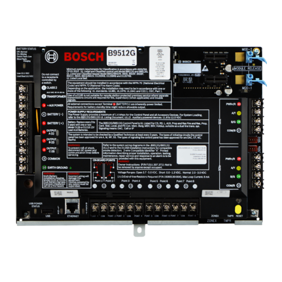
Page 91: Control Panel Board Overview
B9512G/B8512G UL Listing Document, ULLD. Auxiliary powered devices: 11.8 to 12.5 VDC Battery: Replace every 3 to The B9512G/B8512G Control Panel is UL Listed For CS, RS, L, AUX, Prop and Res Fire and Res, Prop, BATTERY ( + ) 5 years with one or two Cent. - Page 92 On-board Ethernet connection, page 48 13 ᅳ On-board Ethernet connector 14 ᅳ LINK LED (yellow) 15 ᅳ USB connector USB power, page 68 16 ᅳ USB POWER STATUS LED 2016.06 | 08 | F.01U.303.996 Installation and System Reference Guide Bosch Security Systems, Inc.
-
Page 93: System Wiring Diagrams
All terminals except Outputs A (1), B (2), and C (3) (Terminals 6, 7, and 8) are supervised. For proper supervision, do not loop wire under terminals. Break the wire run to provide supervision of connections. Bosch Security Systems, Inc. Installation and System Reference Guide 2016.06 | 08 | F.01U.303.996... -
Page 94: Power Supply Side Wiring
12 ᅳ Listed audible signaling devices rated at 12.0 VDC nominal (do not use vibrating type horns) 6 ᅳ B520 Auxiliary Power Supply Module 13 ᅳ To earth ground 7 ᅳ To powered devices 2016.06 | 08 | F.01U.303.996 Installation and System Reference Guide Bosch Security Systems, Inc. -
Page 95: Input Points Wiring With D125B, D130, Or D129
18.3 Input points wiring with or without EOL resistors Notice! For the dual EOL resistor circuit style order ICP-1K22AWG-10, package of 10 1.0 kΩ EOL resistors. Bosch Security Systems, Inc. Installation and System Reference Guide 2016.06 | 08 | F.01U.303.996... -
Page 96: Sdi And Zonex Wiring
Install Fire and Intrusion devices only on separate circuits. Refer to the ICP-SDI-9114 Installation Instructions (P/N: F01U030068). All external connections except Terminal 5 (battery positive) are power limited. 2016.06 | 08 | F.01U.303.996 Installation and System Reference Guide Bosch Security Systems, Inc. - Page 97 D8128D OctoPOPITs connected to the same terminal. Refer to the D8128D Installation Guide (P/N: F01U070537) or the D8129 Operation and Installation Guide (P/N: F01U036302) for specific information. Bosch Security Systems, Inc. Installation and System Reference Guide 2016.06 | 08 | F.01U.303.996...
-
Page 98: Sdi2 Devices General System Wiring
SDI2 bus wiring recommendations Use the following SDI2 bus wiring recommendations for SDI2 installation. The control panel and SDI2 modules use the SDI2 bus to communicate with one another. 2016.06 | 08 | F.01U.303.996 Installation and System Reference Guide Bosch Security Systems, Inc. - Page 99 Maximum cable lengths Follow these rules when wiring the SDI2 bus: – The SDI2 bus requires the use of unshielded cable from 12 AWG to 22 AWG. Bosch Security Systems, Inc. Installation and System Reference Guide 2016.06 | 08 | F.01U.303.996...
-
Page 100: 2-Wire Smoke Wiring (D125B)
POINT 1 COM POINT 2 POINT 3 COM POINT 4 POINT 5 COM POINT 6 POINT 7 COM POINT 8 ETHERNET Figure 18.26: D125B to control panel wiring 2016.06 | 08 | F.01U.303.996 Installation and System Reference Guide Bosch Security Systems, Inc. - Page 101 8 ᅳ Supervised smoke detector to B LOOP positive board point of the panel 4/5 ᅳ Connection to the control panel’s common (one 9 ᅳ Supervised smoke detector to A LOOP positive connection only) Bosch Security Systems, Inc. Installation and System Reference Guide 2016.06 | 08 | F.01U.303.996...
-
Page 102: Approved Applications
Approved applications The UL System Chart references the components that are evaluated and listed by UL for compatibility with B9512G/B8512G control panels. These components meet the basic system requirements for the applicable standard. Refer to Compatible UL listed components, page 107. - Page 103 8 ᅳ Alarm input point 16 ᅳ Safe Use Terminals 1 through 8. (Select only one.) Use a D113 Battery Lead Supervision Module to supervise the battery connections Bosch Security Systems, Inc. Installation and System Reference Guide 2016.06 | 08 | F.01U.303.996...
- Page 104 The following configuration and programming options are required for UL Bank Safe and Vault Systems. Refer to RPS Help or the control panel’s Program Entry Guide for programming information. Safe and Vault protective circuits 2016.06 | 08 | F.01U.303.996 Installation and System Reference Guide Bosch Security Systems, Inc.
-
Page 105: Fire Applications
The control panel does not support multiple detectors in alarm. The control panel is compatible with detectors with optional features. Do not mix detectors from different manufacturers on the same circuit. Bosch Security Systems, Inc. Installation and System Reference Guide 2016.06 | 08 | F.01U.303.996... - Page 106 Install devices according to the manufacturer’s instructions. For more information, refer to Off- board outputs, page 69. For battery calculations, refer to Standby battery requirements and calculations, page 110. 2016.06 | 08 | F.01U.303.996 Installation and System Reference Guide Bosch Security Systems, Inc.
-
Page 107: Enclosures
Test Weekly: Perform a Fire Test weekly. According to UL 864, a Fire Test tests both the AC power and the battery. 19.1.4 Enclosures Mount the control panel assembly in any of the Bosch Security Systems, Inc. enclosures listed: – D2203 Enclosure –... - Page 108 D1640 Required for all UL applications. D1640-CA Required for all cUL applications. Enclosures BATB-40/ BATB-80 D8004 B8103/D8103/ D8109 Enclosure D8108A Enclosure Expansion modules B208 B299 B308 2016.06 | 08 | F.01U.303.996 Installation and System Reference Guide Bosch Security Systems, Inc.
- Page 109 D8130 D9127U/T Wireless B810 B820 Communicators B426 B430 B440 B441 B442 B443 B450 Accessories D113 D130 D132A D133 D134 D161 Suitable for use on approved applications Bosch Security Systems, Inc. Installation and System Reference Guide 2016.06 | 08 | F.01U.303.996...
-
Page 110: Standby Battery Requirements And Calculations
Qty = ______ x Qty = ______ x Qty = ______ B426 ______ x Qty = ______ x Qty = ______ x Qty = ______ 2016.06 | 08 | F.01U.303.996 Installation and System Reference Guide Bosch Security Systems, Inc. - Page 111 Qty = ______ x Qty = ______ x Qty = ______ D8125MUX ______ x Qty = ______ x Qty = ______ x Qty = ______ Bosch Security Systems, Inc. Installation and System Reference Guide 2016.06 | 08 | F.01U.303.996...
- Page 112 Police Station Connected (Bank) 30 (CUL)/15 (UL) Police Station Connected (Mercantile) 30 (CUL)/15 (UL) Local Burglary (Bank) 30 (CUL)/15 (UL) Local Burglary (Mercantile) 30 (CUL)/15 (UL) 2016.06 | 08 | F.01U.303.996 Installation and System Reference Guide Bosch Security Systems, Inc.
-
Page 113: Household Fire Warning Equipment
One D126 Battery = 7 Ah – Two D126 Batteries = 14 Ah – One D1218 Battery = 17.2 or 18 Ah Table 19.15: Household fire ampere-hour (Ah) calculation formula Bosch Security Systems, Inc. Installation and System Reference Guide 2016.06 | 08 | F.01U.303.996... -
Page 114: Ul 365 - Police Station Connected Burglar Alarm Units And Systems
Set Area # Delay Restorals as follows: – Area # Delay Restorals = No (Restoral report is sent when point restores.) 19.7 Conduct testing monthly, with the primary de-energized. 2016.06 | 08 | F.01U.303.996 Installation and System Reference Guide Bosch Security Systems, Inc. -
Page 115: Keypad Installer Menu
0, and then connect it to the control panel. Use the control panel RESET button to enter SERVICE MODE. The rate of flashing of the Heartbeat LED increases while in SERVICE MODE. Bosch Security Systems, Inc. Installation and System Reference Guide 2016.06 | 08 | F.01U.303.996... - Page 116 For simplicity and readability of instructions, this section lists menu steps in succession with the > character separating steps. For example, Go to [1] Program > [1] Reporting > [2] Network > [2] Enhanced Comm Parms. 2016.06 | 08 | F.01U.303.996 Installation and System Reference Guide Bosch Security Systems, Inc.
- Page 117 IP Camera SDI2 Cellular (1) SDI2 Cellular (2) Cloud Plug-in Module Srvc Byp menu Versions menu Cloud menu USB Power menu Exit Figure 20.30: Keypad Installer menu tree Bosch Security Systems, Inc. Installation and System Reference Guide 2016.06 | 08 | F.01U.303.996...
- Page 118 All On menu <All On Delay <All On Instant <All On Select Area *As configured by your security company. ^B94x only. Figure 20.31: B93x/B94x keypads Main menu tree 2016.06 | 08 | F.01U.303.996 Installation and System Reference Guide Bosch Security Systems, Inc.
- Page 119 To exit a menu and return to the previous level, press . Notice! If editing a value on the B91x/B92x/B93x keypads, press and hold [ESC] to delete all the characters. Bosch Security Systems, Inc. Installation and System Reference Guide 2016.06 | 08 | F.01U.303.996...
- Page 120 Use [PREV] or [NEXT] to cycle through the characters. Press [ENTER] to choose the character shown. Network address characters Use the [0] key to enter a period or dash. 2016.06 | 08 | F.01U.303.996 Installation and System Reference Guide Bosch Security Systems, Inc.
-
Page 121: Program Menu
Press [ENTER] to edit the phone destination and then press [NEXT] to go to the format option. Press [ENTER] to edit the phone format for the selected destination. Bosch Security Systems, Inc. Installation and System Reference Guide 2016.06 | 08 | F.01U.303.996... -
Page 122: Reporting > [2] Network Menu Parameters
[Edit] to edit the enhanced communication option. Press the icon or softkey for the desired option. Press [Save] to save the programming. When the keypad shows Parameter Saved, escape from the menu. 2016.06 | 08 | F.01U.303.996 Installation and System Reference Guide Bosch Security Systems, Inc. - Page 123 Installer menu. B93x/B94x keypads configuration of Network Address, Poll Rate (seconds), and Port Number Enter the installer passcode, and then open the [1] Installer menu. Bosch Security Systems, Inc. Installation and System Reference Guide 2016.06 | 08 | F.01U.303.996...
-
Page 124: Reporting > [3] Routing Menu Parameters
Press [ENTER] to select the device. The keypad shows Set route dest 1-4. To keep destination 1, escape from the menu. To change to a different destination (2, 3, or 4), continue to Step 8. 2016.06 | 08 | F.01U.303.996 Installation and System Reference Guide Bosch Security Systems, Inc. - Page 125 /[NEXT] to scroll though the list of routes and go to the route you want to program. Press [Backup] to edit the backup destination device for the selected route. Bosch Security Systems, Inc. Installation and System Reference Guide 2016.06 | 08 | F.01U.303.996...
-
Page 126: Reporting > [4] Personal Note Menu Parameters
Phone number or email address Number ______________________________________________________________________ ______________________________________________________________________ ______________________________________________________________________ ______________________________________________________________________ ______________________________________________________________________ ______________________________________________________________________ ______________________________________________________________________ ______________________________________________________________________ ______________________________________________________________________ ______________________________________________________________________ ______________________________________________________________________ ______________________________________________________________________ ______________________________________________________________________ ______________________________________________________________________ ______________________________________________________________________ ______________________________________________________________________ ______________________________________________________________________ ______________________________________________________________________ ______________________________________________________________________ ______________________________________________________________________ ______________________________________________________________________ ______________________________________________________________________ ______________________________________________________________________ ______________________________________________________________________ 2016.06 | 08 | F.01U.303.996 Installation and System Reference Guide Bosch Security Systems, Inc. -
Page 127: Network > [1] Ethernet > (Choose The Bus Module Or On-Board) > [1] Module
B426. In this menu, you can enable and disable these protocols. Default Module settings DHCP/AutoIP Enable Yes/No UPnP Enable Yes/No IPv4 Address 0.0.0.0 _______________________________ IPv4 Subnet Mask 255.255.255.255 _______________________________ Default Gateway 0.0.0.0 _______________________________ Bosch Security Systems, Inc. Installation and System Reference Guide 2016.06 | 08 | F.01U.303.996... - Page 128 Press [Yes] or [No] – whichever is available – to change the programming. Press [Save] to save the programming. When the keypad shows Parameter Saved, escape from the menu. 2016.06 | 08 | F.01U.303.996 Installation and System Reference Guide Bosch Security Systems, Inc.
-
Page 129: Network > [1] Ethernet > (Choose The Bus Module Or On-Board) > [2] Address
/[NEXT] to move to a different byte, and use the number keys to enter the new numbers. Press [Save] to save the programming. When the keypad shows Parameter Saved, escape from the menu. Bosch Security Systems, Inc. Installation and System Reference Guide 2016.06 | 08 | F.01U.303.996... -
Page 130: Network > [1] Ethernet > (Choose The Bus Module Or On-Board) > [3] Dns
[2] Network > [1] Ethernet > (choose the bus module or on-board) > [3] DNS Parameters menu IPv4 Server Address B91x/B92x keypads configuration of IPv4 Server Address Enter the installer passcode, and then open the [1] Installer menu. 2016.06 | 08 | F.01U.303.996 Installation and System Reference Guide Bosch Security Systems, Inc. - Page 131 When the keypad shows Parameter Saved, escape from the menu. Module Hostname B91x/B92x keypads configuration of Module Hostname Enter the installer passcode, and then open the [1] Installer menu. Bosch Security Systems, Inc. Installation and System Reference Guide 2016.06 | 08 | F.01U.303.996...
-
Page 132: Network > [2] Cellular > (Choose The Sdi2 Cellular Module Or Plug-In Module)
> [1] SIM APN. The keypad shows the DHCP/AutoIP current configuration. Press [Edit] to edit the configuration. Delete existing characters, if necessary, and then enter the new characters. Press [Save] to save the changes. 2016.06 | 08 | F.01U.303.996 Installation and System Reference Guide Bosch Security Systems, Inc. - Page 133 Go to [1] Program > [2] Network > [2] Cellular > (choose the SDI2 cellular module or plug-in module) > [4] SIM PIN. The keypad shows the current configuration. Press [ENTER] to edit the configuration. Bosch Security Systems, Inc. Installation and System Reference Guide 2016.06 | 08 | F.01U.303.996...
-
Page 134: Rps > [1] Rps Passcode Menu Parameters
Delete existing numbers, if necessary, and then enter the new numbers. Press [ENTER] to save the programming. When the keypad shows Parameter Saved, escape from the menu. 2016.06 | 08 | F.01U.303.996 Installation and System Reference Guide Bosch Security Systems, Inc. -
Page 135: Rps > [3] Rps Ip Address Menu Parameters
Go to [1] Program > [3] RPS > [3] RPS Port Number. Press [ENTER] to edit RPS port number. Delete the existing number, if necessary, and then enter the new number. Press [ENTER] to save the programming. Bosch Security Systems, Inc. Installation and System Reference Guide 2016.06 | 08 | F.01U.303.996... -
Page 136: Area Options Menu Parameters
Area 22* Area 23* Area 24* Area On Yes/No Yes/No Yes/No Yes/No Account Number ______________ ______________ ______________ ______________ Area 25* Area 26* Area 27* Area 28* 2016.06 | 08 | F.01U.303.996 Installation and System Reference Guide Bosch Security Systems, Inc. - Page 137 ______________ ______________ ______________ ______________ *Supported by the B9512G only. Area On B91x/B92x keypads configuration of Area On Enter the installer passcode, and then open the [1] Installer menu. Go to [1] Program > [4] Area Options. The keypad toggles between showing the Area On state and the account number for the selected areas.
-
Page 138: Keypad Menu Parameters
You can also use this menu to identify the keypad type. The B9512G supports up to 32 keypads, including up to 16 SDI keypads. The B8512G supports up to 16 keypads, including up to 16 SDI keypads. - Page 139 Panel Wide Keypad 32* No keypad / B91x / B92x / B93x / B94x No Device / Area Wide / Acct Wide / Panel Wide *Supported by the B9512G only. Bosch Security Systems, Inc. Installation and System Reference Guide 2016.06 | 08 | F.01U.303.996...
-
Page 140: Users Menu Parameters
To add and remove users, change users passcodes, and perform other user functions from the keypad, you must use the Users menu from the Main menu. Refer to the Control Panels (B9512G/B8512G/B5512/B4512/B3512) Owner’s Manual for more information. Users (In the Installer menu) B91x/B92x keypads configuration of Users Enter the installer passcode, and then open the [1] Installer menu. -
Page 141: Points Menu Parameters
Pull Station Point Index 4 Smoke Detector Point Index 5 Smoke Detector w/Verification Point Index 6 Bell Supervision - D192G Point Index 7 Part On: Instant Bosch Security Systems, Inc. Installation and System Reference Guide 2016.06 | 08 | F.01U.303.996... - Page 142 Alarm Verify Resettable Alarm Abort Wireless Point Supervision _____ _____ (4)____ (4)____ (4)____ (4)____ _____ _____ Time Custom Function Disabled Disabled Disabled Disabled Disabled Disabled Disabled Disabled 2016.06 | 08 | F.01U.303.996 Installation and System Reference Guide Bosch Security Systems, Inc.
- Page 143 00:00 00:00 00:00 00:00 Delay Response Disarmed 00:00 00:00 00:00 00:00 00:00 00:00 00:00 00:00 Delay Response Armed 00:00 00:00 00:00 00:00 00:00 00:00 00:00 00:00 Bosch Security Systems, Inc. Installation and System Reference Guide 2016.06 | 08 | F.01U.303.996...
- Page 144 __(1)__ __(0)__ __(0)__ __(0)__ __(0)__ __(0)__ __(0)__ __(0)__ Display as Device Local While Disarmed Local While Armed Disable Restorals FA Returnable Bypass Returnable Bypassable Swinger Bypass 2016.06 | 08 | F.01U.303.996 Installation and System Reference Guide Bosch Security Systems, Inc.
- Page 145 00:00 00:00 00:00 00:00 Delay Response Disarmed 00:00 00:00 00:00 00:00 00:00 00:00 00:00 00:00 Delay Response Armed 00:00 00:00 00:00 00:00 00:00 00:00 00:00 00:00 Bosch Security Systems, Inc. Installation and System Reference Guide 2016.06 | 08 | F.01U.303.996...
- Page 146 __(0)__ __(0)__ __(0)__ ______ ______ ______ (1) ____ Display as Device Local While Disarmed Local While Armed Disable Restorals FA Returnable Bypass Returnable Bypassable Swinger Bypass 2016.06 | 08 | F.01U.303.996 Installation and System Reference Guide Bosch Security Systems, Inc.
- Page 147 00:00 00:00 00:00 00:00 Delay Response 00:00 00:00 00:00 00:00 00:00 00:00 00:00 00:00 Disarmed Delay Response Armed 00:00 00:00 00:00 00:00 00:00 00:00 00:00 00:00 Bosch Security Systems, Inc. Installation and System Reference Guide 2016.06 | 08 | F.01U.303.996...
- Page 148 Output Response Type ______ ______ ______ ______ ______ ______ ______ ______ Display as Device Local While Disarmed Local While Armed Disable Restorals FA Returnable Bypass Returnable 2016.06 | 08 | F.01U.303.996 Installation and System Reference Guide Bosch Security Systems, Inc.
- Page 149 00:00 00:00 00:00 00:00 00:00 00:00 *Point Indexes 33 through 63 are supported by the B9512node:1981583935299317871133 only, and have the same defaults as Point Index 31. Bosch Security Systems, Inc. Installation and System Reference Guide 2016.06 | 08 | F.01U.303.996...
- Page 150 __ __ __ __ __ __ __ __ __ __ __ __ __ __ __ __ __ __ __ __ __ __ __ __ __ __ __ 2016.06 | 08 | F.01U.303.996 Installation and System Reference Guide Bosch Security Systems, Inc.
- Page 151 Press [Source] to view and edit the source, and then press [Edit] to edit the source. /[PREV] or /[NEXT] to scroll through the available options. Press [Save] to save the programming. When the keypad shows Parameter Saved, escape from the menu. Bosch Security Systems, Inc. Installation and System Reference Guide 2016.06 | 08 | F.01U.303.996...
-
Page 152: Disable Programming Menu
Press [ENTER] to disable keypad programming, and then press [NEXT] to go to the No option. Press [ENTER] to save the programming. When the keypad shows Parameter Saved, escape from the menu. 2016.06 | 08 | F.01U.303.996 Installation and System Reference Guide Bosch Security Systems, Inc. -
Page 153: Wireless Menu
Verify the RFID shown on the keypad matches the RFID label on the activated device. 20.2.2 [1] RF Point Menu> [2] Replace Point RFID In this menu, you can replace RFID points. Bosch Security Systems, Inc. Installation and System Reference Guide 2016.06 | 08 | F.01U.303.996... -
Page 154: Rf Point Menu> [3] Remove Point Rfid
Press [Remove] to remove the RFID point. The keypad removes the device and shows Point RFID Removed. Escape from the menu. 2016.06 | 08 | F.01U.303.996 Installation and System Reference Guide Bosch Security Systems, Inc. -
Page 155: Rf Repeater Menu > [1] Add Repeater
/[NEXT] to scroll though the list of repeaters, and go to the repeater you want to replace, or simply enter the repeater number. Press [ENTER] to replace the device. The keypad instructs you to reset the new device. Bosch Security Systems, Inc. Installation and System Reference Guide 2016.06 | 08 | F.01U.303.996... -
Page 156: Rf Repeater Menu > [3] Remove Repeater
Press [State] to view the state. The menu scrolls through the following sub-categories, with the results of the diagnostic check: State, Tamper, Low-Battery, Maintenance. When finished viewing the information, escape from the menu. 2016.06 | 08 | F.01U.303.996 Installation and System Reference Guide Bosch Security Systems, Inc. -
Page 157: Rf Diagnostic Menu > [2] Rf Repeater Menu
State, Missing, Tamper, Low-Battery, Low- Battery. When finished viewing the information, escape from the menu. Signal Strength (for RF repeaters) Bosch Security Systems, Inc. Installation and System Reference Guide 2016.06 | 08 | F.01U.303.996... -
Page 158: Diags Menu
When finished viewing the information, escape from the menu. Connection B91x/B92x keypads use of Connection Enter the installer passcode, and then open the [1] Installer menu. 2016.06 | 08 | F.01U.303.996 Installation and System Reference Guide Bosch Security Systems, Inc. -
Page 159: Cellular Menu
– ESN (The cellular radio electronic serial number.) – Model (The cellular radio model.) – Version (The cellular radio version.) When finished viewing the information, escape from the menu. Bosch Security Systems, Inc. Installation and System Reference Guide 2016.06 | 08 | F.01U.303.996... -
Page 160: Ip Camera
Enter the installer passcode, and then open the [1] Installer menu. Go to [3] Diags > [5] Cloud. The keypad shows the Cloud ID, which is also on a label on the control panel. 2016.06 | 08 | F.01U.303.996 Installation and System Reference Guide Bosch Security Systems, Inc. -
Page 161: Serv Byp (Service Bypass) Menu
Enter the installer passcode, and then open the [1] Installer menu. Go to [5] Versions. Use [PREV] or [NEXT] to cycle through the list of items for which you can view the version. Bosch Security Systems, Inc. Installation and System Reference Guide 2016.06 | 08 | F.01U.303.996... - Page 162 Go to [5] Versions. Press the icon or softkey for the item for which you want view the version. The keypad shows the version. Escape from the menu. 2016.06 | 08 | F.01U.303.996 Installation and System Reference Guide Bosch Security Systems, Inc.
-
Page 163: Cloud Menu
Go to [7] USB Power. The keypad shows the current status, On or Off. Press Turn On or Turn Off, as desired. Escape from the menu. Bosch Security Systems, Inc. Installation and System Reference Guide 2016.06 | 08 | F.01U.303.996... -
Page 164: Specifications
Control Panel: Idle 190 mA; Alarm 265 mA requirements Refer to the Current Rating Chart for Standby Battery Calculations section in the Control Panels (B9512G/B8512G) Installation and System Reference Guide (this document) for the current draw requirements of other system components. Power outputs All external connections are power-limited except battery terminals. -
Page 165: Wire Requirements
18 AWG min (up to 14 AWG max) 18 AWG min (up to 14 AWG max) + AUX POWER Terminal accommodates 14 to 22 AWG, use appropriate wire size based on current Bosch Security Systems, Inc. Installation and System Reference Guide 2016.06 | 08 | F.01U.303.996... - Page 166 166 en | Specifications Control Panels BATTERY - Bosch supplied wire lead, included with control panel.. BATTERY + Output A (1) Terminal accommodates 14 to 22 AWG, use appropriate wire size based on current Output B (2) Output C (3)
- Page 167 22 AWG min (up to 14 AWG max) SDI2 DATA BUS A SDI2 POWER Terminal accommodates 14 to 22 AWG, use appropriate wire size based on peripheral device current Bosch Security Systems, Inc. Installation and System Reference Guide 2016.06 | 08 | F.01U.303.996...
-
Page 168: Appendix
50*, 51*, 52*, 53*, 54*, 55*, 56*, 57*, 58*, 59* 501 - 508, 511 - 518, 521 - 528, 531 - 538, 541 - 548, 551 - 558, 561 - 568, 571 - 578, 581 - 588 , 591 - 598 *Supported by the B9512G only. Tab. 22.16: Octo-input module corresponding point numbers 22.1.2... -
Page 169: B308 Address Settings
50*, 51*, 52*, 53*, 54*, 55*, 56*, 57*, 58*, 59* 501 – 508, 511 – 518, 521 – 528, 531 – 538, 541 – 548, 551 – 558, 561 – 568, 571 – 578, 581 – 588 , 591 – 598 *Supported by the B9512G only. Tab. 22.17: Octo-output module valid relay numbers 22.1.4 D8128D address settings The D8128D OctoPOPIT has two sets of DIP switches. -
Page 170: D8129 Address Settings
For the D8128D OctoPOPITs assigned to Points 121 to 127, 241, and 247, set Point Input Switch 8 to the OPEN position. The B9512G uses Points 9 to 127 on ZONEX 1 and Points 129 to 247 on ZONEX 2. B8512G uses only Points 9 to 99 on ZONEX 1. -
Page 171: B901 Address Settings
Appendix | en 171 Octo-relay module address setting Control panel relay number ZONEX Number On-On-On-Off-On 121– 128* * Supported by the B9512G only. 22.1.6 B901 address settings Valid addresses for SDI2 (or SDIx in SDI2 mode) B901 addresses Designation B9512G 01 – 32... -
Page 172: D9210C Address Settings
Door #2 LOCKED SDI #35 Door #3 LOCKED SDI #36 Door #4 LOCKED SDI #37 Door #5 LOCKED SDI #38 Door #6 LOCKED SDI #39 Door #7 2016.06 | 08 | F.01U.303.996 Installation and System Reference Guide Bosch Security Systems, Inc. -
Page 173: Sdi Keypad Address Settings
A valid local RPS access RsF01 Successful Download/ 1 412 00 000 occurred Access A valid remote RPS access RsssF NphhhRS Successful Download/ 1 412 00 000 callback occurred Access Bosch Security Systems, Inc. Installation and System Reference Guide 2016.06 | 08 | F.01U.303.996... - Page 174 Trouble Restoral Bypass by Sked Nspppp Nriaa/ Zone/Sensor Bypass 1 570 aa ppp aikkkUBpppp Bypass by User Nspppp Nriaa/ Zone/Sensor Bypass 1 570 aa ppp idiiiiUBpppp 2016.06 | 08 | F.01U.303.996 Installation and System Reference Guide Bosch Security Systems, Inc.
- Page 175 Communication trouble by NsB01 NphhhYK Communication Trouble 3 350 00 000 phone restored Restore Configuration Failure TssssD NpiddddEP System Peripheral Trouble 1 330 00 zzz (Device) Bosch Security Systems, Inc. Installation and System Reference Guide 2016.06 | 08 | F.01U.303.996...
- Page 176 1 406 aa uuu Fire Drill Start TsssF Nriaa/idiiiiFL Fire Test Start 1 604 aa iii Fire Drill End RsssF Nriaa/idiiiiNF Fire Test End 3 604 aa iii 2016.06 | 08 | F.01U.303.996 Installation and System Reference Guide Bosch Security Systems, Inc.
- Page 177 NriaaUYpppp Loss of Supervision – RPM 1 382 aa ppp Invalid Popit Address Restore Rpppp NriaaBRpppp Loss of Supervision – RPM 3 382 aa ppp Restore Bosch Security Systems, Inc. Installation and System Reference Guide 2016.06 | 08 | F.01U.303.996...
- Page 178 1 452 aa uuu Parameters changed NsD02 Panel Programming 1 306 00 000 Changed Personal Notification TsB01 NpiddddYS Communication Trouble 1 350 0 zzz Communication Trouble 2016.06 | 08 | F.01U.303.996 Installation and System Reference Guide Bosch Security Systems, Inc.
- Page 179 3 344 00 RF Transmitter Hss001 NriaaFRpppp Maintenance Alert Restore 3 393 aa ppp RF Transmitter Low Battery Tspppp NriaaXTpppp RF Low Battery 1 384 aa ppp Bosch Security Systems, Inc. Installation and System Reference Guide 2016.06 | 08 | F.01U.303.996...
- Page 180 SDI2 device is restored from RsssD NpiddddEN Expansion Module Failure 3 333 00 000 missing SDI2 Open Trouble TsssD NpiiddddET Expansion Module Failure 1 333 00 2016.06 | 08 | F.01U.303.996 Installation and System Reference Guide Bosch Security Systems, Inc.
- Page 181 Test Report – System Off- RsssE NRY & see Periodic Test – System 1 608 00 000 normal, Expanded Status D6600 CIM for Trouble Present Status Items Bosch Security Systems, Inc. Installation and System Reference Guide 2016.06 | 08 | F.01U.303.996...
-
Page 182: Device Numbers (Zzz, Dddd)
SDI Access Modules 1 through 8 01 - 32 601 - 632 SDI2 Access Modules 1 through 32 516 - 531 IP Cameras 1 through 16 OnBrd Control Panel Enclosure 2016.06 | 08 | F.01U.303.996 Installation and System Reference Guide Bosch Security Systems, Inc. -
Page 183: Communication Trouble Device Numbers (Zzzz)
Special point numbers identify the originator of manually created keypad alarm events. All special point numbers are defined in the table below. Originating Keypad Reported Number Keypad 1 - 32 901 - 932 Bosch Security Systems, Inc. Installation and System Reference Guide 2016.06 | 08 | F.01U.303.996... -
Page 184: Autoip
Navigate to the saved file and double-click on it to add it to the host computer’s registry. – Restart the host computer. Text for the AutoIP.reg file: Windows Registry Editor Version 5.00 [HKEY_LOCAL_MACHINE\SYSTEM\CurrentControlSet\Services\Tcpip\Parameters] "IPAutoconfigurationEnabled"=dword:00000001 2016.06 | 08 | F.01U.303.996 Installation and System Reference Guide Bosch Security Systems, Inc. - Page 186 Bosch Security Systems, Inc. Bosch Sicherheitssysteme GmbH 130 Perinton Parkway Robert-Bosch-Ring 5 Fairport, NY 14450 85630 Grasbrunn Germany www.boschsecurity.com © Bosch Security Systems, Inc., 2016...
Need help?
Do you have a question about the B9512G and is the answer not in the manual?
Questions and answers