Bosch B6512 Installation Manual
Hide thumbs
Also See for B6512:
- Installation manual (147 pages) ,
- Quick user manual (56 pages) ,
- Operation manual (224 pages)

Related Manuals for Bosch B6512


Summary of Contents for Bosch B6512
- Page 1 Control panels B6512/B5512/B4512/B3512 (B5512E/B4512E/B3512E) UL Installation manual...
-
Page 3: Table Of Contents
Table of contents | en Table of contents Introduction About documentation 1.1.1 Related documentation Bosch Security Systems, Inc. product manufacturing dates System overview Parts list Control panel capacities Control panel installation Installing the enclosure and wiring label Installing the control panel 3.2.1... -
Page 4: Introduction
These indicate a hazardous situation which, if not avoided, could result in death or serious injury. Copyright This document is the intellectual property of Bosch Security Systems, Inc. and is protected by copyright. All rights reserved. Trademarks All hardware and software product names used in this document are likely to be registered trademarks and must be treated accordingly. -
Page 5: Bosch Security Systems, Inc. Product Manufacturing Dates
Located on the documentation CD shipped with the module. Bosch Security Systems, Inc. product manufacturing dates Use the serial number located on the product label and refer to the Bosch Security Systems, Inc. website at http://www.boschsecurity.com/datecodes/. Bosch Security Systems B.V. -
Page 6: System Overview
Control panels ship assembled from the factory with the following parts: Literature – Control Panels (B6512/B5512/B4512/B3512) UL Installation Manual – Control Panels (B6512/B5512/B4512/B3512) Operation Manual – Control Panels (B6512/B5512/B4512/B3512) SIA Quick Reference Guide – Control Panels (B6512/B5512/B4512/B3512) Documentation CD – Enclosure Wiring Label (B6512/B5512/B4512/B3512) HW pack –... -
Page 7: Control Panel Installation
Pull the wires into the enclosure through the knockouts. Position the supplied enclosure wiring label on the inside of the enclosure door. Installing the control panel Identify the control panel mounting location in the enclosure. Bosch Security Systems B.V. UL Installation manual 2019-12 | 10 | F.01U.287.185... - Page 8 If you install a B12, rest the hook tabs on the mounting plate hooks within the enclosure. Secure the lock-down tab to the plate mounting hole with the screw provided. 2019-12 | 10 | F.01U.287.185 UL Installation manual Bosch Security Systems B.V.
-
Page 9: Earth Ground
The OUTPUT A LED lights when OUTPUT A is active. Control panel to module wiring overview You can use interconnect or terminal wiring to connect devices to the control panel. Bosch Security Systems B.V. UL Installation manual 2019-12 | 10 | F.01U.287.185... - Page 10 For more information on interconnect wiring, refer to SDI2 interconnect wiring. 7 COM 8 COM AUX NO C NC 18VAC + BAT - B COM B COM OUTPUT A PWR A B COM 2019-12 | 10 | F.01U.287.185 UL Installation manual Bosch Security Systems B.V.
-
Page 11: Power Supply
Connect the other end to the negative (-) side of the battery. Connect the red battery lead to 5. Connect the other end to the positive (+) side of the battery. Bosch Security Systems B.V. UL Installation manual 2019-12 | 10 | F.01U.287.185... - Page 12 3 ᅳ 0.25 in (6.4 mm) minimum 4 ᅳ Battery terminals. BAT- is non-power limited 5 ᅳ Battery wires 6 ᅳ 12 V sealed lead-acid rechargeable battery (D126/D1218) 7 ᅳ Sensor loop wires 2019-12 | 10 | F.01U.287.185 UL Installation manual Bosch Security Systems B.V.
-
Page 13: Battery Maintenance
For Burglar applications, an additional 2 A of alarm power is available, allowing 2 A of standby current and up to 4 A of alarm current. The control panels support the following number of B520 modules: – B6512. 4 Bosch Security Systems B.V. UL Installation manual 2019-12 | 10 | F.01U.287.185... -
Page 14: Sdi2 Address Settings
Tighten the supplied mounting screws. Wiring to earth ground To help prevent damage from electrostatic charges or other transient electrical surges, connect the system to earth ground before making other connections. 2019-12 | 10 | F.01U.287.185 UL Installation manual Bosch Security Systems B.V. - Page 15 Use the terminal strip labeled with PWR, A, B, and COM for SDI2 IN to wire to corresponding control panel SDI2 terminals. Do not use interconnect wiring. Use 12 AWG to 22 AWG (2.0 mm to 0.6 mm) wire. Bosch Security Systems B.V. UL Installation manual 2019-12 | 10 | F.01U.287.185...
-
Page 16: Powered Device And Battery Wiring
When you wire the output of a B520 to a SDI2 module, the B520 provides power to the module while passing through data between the control panel and the module. 2019-12 | 10 | F.01U.287.185 UL Installation manual Bosch Security Systems B.V. - Page 17 You must wire BATT 1. You must wire BATT 2 if you configure the B520 for two batteries. When you use BATT 2, both batteries must have the same rating. Maximum standby power cannot exceed 36 Ah. Callout ᅳ Description Bosch Security Systems B.V. UL Installation manual 2019-12 | 10 | F.01U.287.185...
- Page 18 1 ᅳ B520 Auxiliary Power Supply Module 2 ᅳ Battery 2 (BATT 2) - (12 V nominal lead acid) 3 ᅳ Battery 1 (BATT 1) - (12 V nominal lead acid) 2019-12 | 10 | F.01U.287.185 UL Installation manual Bosch Security Systems B.V.
-
Page 19: On-Board Outputs
The default configuration for Output A makes it a powered output providing alarm power. Use OUTPUT PARAMETERS in RPS or in the Installer Services Portal programming tool (available in Europe, Middle East, Africa, and China) to configure programmable outputs. Bosch Security Systems B.V. UL Installation manual 2019-12 | 10 | F.01U.287.185... -
Page 20: Open Collector Outputs
2 ᅳ D134 Dual Relay Module Use OUTPUT PARAMETERS in RPS or in Installer Services Portal programming tool (available in Europe, Middle East, Africa, and China) to configure programmable outputs. 2019-12 | 10 | F.01U.287.185 UL Installation manual Bosch Security Systems B.V. -
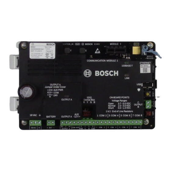
Page 21: Control Panel Board Overview
8 ᅳ On-board Ethernet connector 18 ᅳ Terminals for Output A (optional) 9 ᅳ USB connector 19 ᅳ Battery terminals 10 ᅳ Heartbeat LED (blue) 20 ᅳ 18 VAC power input terminals Bosch Security Systems B.V. UL Installation manual 2019-12 | 10 | F.01U.287.185... -
Page 22: System Wiring Diagrams
9 ᅳ Supervised sensor loops, points 1 to 8 (Initiating Hz (Canada: an ICP-TR1822-CA Plug-in Transformer Device Circuits) 120 VAC primary, 18 VAC 22 VA secondary) 3 ᅳ To earth ground 10 ᅳ To ICP-EZTS Tamper Switch 2019-12 | 10 | F.01U.287.185 UL Installation manual Bosch Security Systems B.V. -
Page 23: Battery Lead Supervision Wiring
PWR A B COM Callout ᅳ Description 1 ᅳ D113 Supervision module, battery lead, if required 2 ᅳ Batteries 3 ᅳ To supervision point 4 ᅳ Control panel Bosch Security Systems B.V. UL Installation manual 2019-12 | 10 | F.01U.287.185... -
Page 24: 2-Wire Smoke Wiring (B201)
+ BAT - PWR A B COM OUTPUT A PASS-THRU SMOKE Callout ᅳ Description 1 ᅳ Control panel 2 ᅳ Interconnect wiring cable 3 ᅳ B201 4 ᅳ EOL resistor 2019-12 | 10 | F.01U.287.185 UL Installation manual Bosch Security Systems B.V. -
Page 25: 2-Wire Smoke Wiring (D125B)
11 ᅳ Output A jumper (under cover) set to AUX PWR You can also use Output B or C in conjunction with a D133 or D134 relay module. Bosch Security Systems B.V. UL Installation manual 2019-12 | 10 | F.01U.287.185... -
Page 26: Input Point Wiring, Dual Eol Resistor Circuit Style
The control panel does not have an on-board NAC. For systems requiring a NAC, use a D192G. Notice! UL requirement For UL Listed fire alarm applications, install a D192G. For detailed instructions, refer to the corresponding document listed in Related documentation, page 4. 2019-12 | 10 | F.01U.287.185 UL Installation manual Bosch Security Systems B.V. - Page 27 2 ᅳ Output jumper set to configure OUTPUT A terminal C for AUX POWER (jumper cover removed) 3 ᅳ D192G 4 ᅳ 1k Ω EOL resistor (P/N: F01U033966) Bosch Security Systems B.V. UL Installation manual 2019-12 | 10 | F.01U.287.185...
-
Page 28: Keyswitch Wiring
Keyswitches are not intended for use in UL listed systems. SDI2 devices general system wiring 7 COM 8 NO C NC COM AUX PWR A B COM OUTPUT A 2019-12 | 10 | F.01U.287.185 UL Installation manual Bosch Security Systems B.V. -
Page 29: Sdi2 Bus Wiring Recommendations
SDI2 modules use the SDI2 bus to communicate with one another. You can wire modules via home run, daisy chain, or single level T-tap anywhere on the SDI2 bus. Bosch Security Systems B.V. UL Installation manual 2019-12 | 10 | F.01U.287.185... - Page 30 Callout ᅳ Description 1 ᅳ Control panel 2 ᅳ SDI2 device (module or keypad) 3 ᅳ Daisy chain wiring 4 ᅳ Single-level T-tapped wiring 5 ᅳ Home run wiring 2019-12 | 10 | F.01U.287.185 UL Installation manual Bosch Security Systems B.V.
- Page 31 Table 7.1: Maximum cable length Notice! Use unshielded cable only. Maximum capacitance of 140nF (140,000 pF) per system. Contact the wire manufacturer for the capacitance ratings of the wire being used. Bosch Security Systems B.V. UL Installation manual 2019-12 | 10 | F.01U.287.185...
-
Page 32: Wiring Label
Avertissement : guide de l'utilisateur (réf. : F01U287181) : seul l'occupant est autorisé à le retirer. Minimum system requirements for Classification in accordance with ANSI/SIA CP-01-2010 Bosch Security Systems, Inc. recommends testing the entire system UL Listed and Classified control unit Model B5512, B4512 or B3512;... -
Page 33: Specifications
13.4 V - Battery Restoral Report sent. Battery float charged. Environmental Temperature 0℃ to +49℃ (+32℉ to 122℉) Relative Humidity 5% to 93% at +32℃ (+90℉) non-condensing Arming stations B940W, B942/B942W, B930, B921C, B920, B915/B915I, Keyswitch Bosch Security Systems B.V. UL Installation manual 2019-12 | 10 | F.01U.287.185... -
Page 34: Wire Requirements
18 AWG to 12 AWG (1.02 mm to 2 mm) Earth ground 16 AWG to 14 AWG (1.5 mm to 1.8 mm) BAT + Battery + Bosch supplied wire lead, included with control panel.. BAT - Battery - OUTPUT A NO Output A normally open 22 AWG to 12 AWG (0.65 mm to 2 mm) - Page 35 Specifications | en Point 3/4 common Point 4 Point 5 Point 5/6 common Point 6 Point 7 Point 7/8 common Point 8 OUTPUT B Output B OUTPUT C Output C Bosch Security Systems B.V. UL Installation manual 2019-12 | 10 | F.01U.287.185...
- Page 36 | Specifications Control panels 2019-12 | 10 | F.01U.287.185 UL Installation manual Bosch Security Systems B.V.
- Page 38 Bosch Security Systems B.V. Torenallee 49 5617 BA Eindhoven Netherlands www.boschsecurity.com © Bosch Security Systems B.V., 2019...
Need help?
Do you have a question about the B6512 and is the answer not in the manual?
Questions and answers