Table of Contents
Advertisement
Quick Links
ASSEMBLY MANUAL
WWW.SEAGULLMODELS.COM
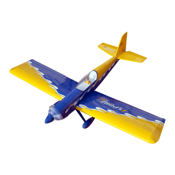
ISPORTS
10
cc
" Graphics and specifications may change without notice " .
Specifications:
ALMOST
Wingspan---------------65.0 in (165 cm).
Wing area----------------821.5 sq.in (53.0 sq.dm).
Weight-------------------7.1 - 7.9 lbs (3.2 - 3.6 kg).
READY TO FLY
Length-------------------51.9 in (131.7cm).
Engine-------------------0.55 - 0.61 cu.in -2 stroke
...................................10cc - 15cc.
Radio--------------------5 channels with 7 servos.
Electric conversion: Optional.
MS: 210
www.seagullmodels.com
1
Advertisement
Table of Contents

Related Manuals for Seagull Models ISPORTS 10cc


Summary of Contents for Seagull Models ISPORTS 10cc
- Page 1 ASSEMBLY MANUAL WWW.SEAGULLMODELS.COM ISPORTS “ Graphics and specifications may change without notice “ . Specifications: ALMOST Wingspan---------------65.0 in (165 cm). Wing area----------------821.5 sq.in (53.0 sq.dm). Weight-------------------7.1 - 7.9 lbs (3.2 - 3.6 kg). READY TO FLY Length-------------------51.9 in (131.7cm). Engine-------------------0.55 - 0.61 cu.in -2 stroke ........10cc - 15cc.
-
Page 2: Kit Contents
Instruction Manual. INTRODUCTION. Thank you for choosing the ISPORT ARTF by SEAGULL MODELS COMPANY LTD,. The ISPORT was designed with the intermediate/advanced sport flyer in mind. It is a semi scale airplane which is easy to fly and quick to assemble. The airframe is onventionally built using balsa, plywood to make it stronger than the average ARTF, yet the design allows the aeroplane to be kept light. -
Page 3: Hinging The Ailerons
WWW.SEAGULLMODELS.COM HINGING THE AILERONS. KIT CONTENTS. SEA2101 Fuselage Note : The control surfaces, including the ai- SEA2102 Wing set lerons, elevators, and rudder, are prehinged SEA2103 Tail set with hinges installed, but the hinges are not glued in place. It is imperative that you prop- SEA2104 Canopy Hatch erly adhere the hinges in place per the steps... - Page 4 ISPORT 10-15cc Instruction Manual. 8) After both ailerons are securely hinged, firmly grasp the wing panel and aileron to make sure the hinges are securely glued and cannot be pulled out. Do this by carefully ap- plying medium pressure, trying to separate the aileron from the wing panel.
- Page 5 WWW.SEAGULLMODELS.COM T-pin. Epoxy. Hinge. 3) Slide the aileron on the wing panel until there is only a slight gap. The hinge is now centered on the wing panel and aileron. Re- move the T-pins and snug the aileron against the wing panel. A gap of 1/64” or less should be maintained between the wing panel and aileron.
-
Page 6: Hinging The Elevators
ISPORT 10-15cc Instruction Manual. 8) After both ailerons are securely hinged, firmly grasp the wing panel and aileron to make sure the hinges are securely glued and Epoxy. cannot be pulled out. Do this by carefully applying medium pressure, trying to sepa- rate the aileron from the wing panel. - Page 7 WWW.SEAGULLMODELS.COM Epoxy. Epoxy. INSTALL ELEVATOR CONTROL HORN. Install the elevator control horn using the same method as same as the aileron control horns. Epoxy. INSTALL FLAP CONTROL HORN. Elevator control horn. Install the flap control horn using the same method as same as the aileron con- trol horns.
-
Page 8: Installing The Stopper Assembly
ISPORT 10-15cc Instruction Manual. 2) Use four 4x30mm head bolts and four INSTALL RUDDER CONTROL HORN. 4mm washers to attach the engine mount rails to the firewall. Tighten the screws . Repeat steps to install the rudder control Make sure to use threadlock on the screws to horn as same as steps done for ailerons. -
Page 9: Fuel Tank Installation
WWW.SEAGULLMODELS.COM 5) With the stopper assembly in place, the weighted pick-up should rest away from the rear of the tank and move freely inside the tank. The top of the vent tube should rest just below the top of the tank. It should not touch the top of the tank. -
Page 10: Installing The Battery
ISPORT 10-15cc Instruction Manual. INSTALLING THE MAIN LANDING GEAR TO FUSELAGE. Balsa block. Vent tube. 1) The blind nuts for securing the land- ing gear are already mounted inside the fuselage. 2) Using the hardware provided, mount the main landing gear to the fuselage. Fuel pick up tube. - Page 11 WWW.SEAGULLMODELS.COM Drill a hole. 8mm. 14mm. 3) You have to trim each axle using a tool cutting and cut-off wheel. 4) Slide the collar to the axle and setscrew the collars to secure the collar to the axle and then slider the wheel on the axle with M4x20mm a drop of oil on the axle so the wheel will spin freely when installed.
-
Page 12: Installing The Fuselage Servos
ISPORT 10-15cc Instruction Manual. 6) Slide the threaded end of the axle INSTALLING THE FUSELAGE SERVOS. through the hole in the bottom of the landing gear leg. Use a washer and lock- Because the size of servos differ, you nut to tighten the axle to the landing gear. may need to adjust the size of the precut Make sure to use threadlock on the nut so opening in the mount. -
Page 13: Mounting The Engine
WWW.SEAGULLMODELS.COM Throttle. Rudder. Trim and cut. Elevator. INSTALLING THE SWITCH RECEIVER. Install the switch into the precut hole in the side, in the fuselage. Switch. 3/32” Hole. MOUNTING THE ENGINE. 1) Position the engine with the drive washer (110mm) forward of the firewall as shown. - Page 14 ISPORT 10-15cc Instruction Manual. 7) Slide the throttle pushrod wire into the tube. Position the engine between the mounts. Use four M4x30mm machine screws to secure the engine to the mount as shown. 3) Use a drill to drill the four holes in the engine mount rails.
- Page 15 WWW.SEAGULLMODELS.COM Because of the size of the cowl, it may be nec- essary to use a needle valve extension for the high speed needle valve. Make this out of suf- ficient length 1.5mm wire and install it into the end of the needle valve. Secure the wire in place by tightening the set screw in the side of the needle valve.
- Page 16 ISPORT 10-15cc Instruction Manual. - Model size: .46-.52 size models - Motor: 35mm 830 rev per volt - Propeller: 12x6 ~ 13x6 - ESC: 60A - Lipo Batteries: 4 cell 4200mA 3x10mm 2) Attach the electric motor box to the firewall suitable with the cross lines drawn on the electric motor box and fire- wall.
- Page 17 WWW.SEAGULLMODELS.COM M3x15mm 4) Locate the plywood battery tray to the fuselage. Tighten the screws using machine screws M3x15mm to secure the tray in 4mm. position. 3) Attach the motor to the front of the electric motor box using four 4mm blind nut, four M3x15mm hex head bolts to se- 110 mm cure the motor.
-
Page 18: Installing The Aileron -Flap Servos
ISPORT 10-15cc Instruction Manual. INSTALLING THE AILERON -FLAP Speed control. SERVOS. Battery. INSTALLING THE SPINNER. Servos Install the spinner backplate, propeller Small weight and spinner cone. Thread Because the size of servos differ, you may need to adjust the size of the precut opening in the mount. - Page 19 WWW.SEAGULLMODELS.COM C/A glue 4) Apply 2-3 drops of thin C/A to each of the mounting holes. Allow the C/A to cure without using accelerator. C/A glue 5) Use dental floss to secure the connec- tion so they cannot become unplugged. 6) Secure the servo to the aileron hatch using Phillips screwdriver and the screws provided with the servo.
-
Page 20: Installation
ISPORT 10-15cc Instruction Manual. Use a felt tip pen to mark the wire where it crosses the hole. Use a pair of pliers to put a shrp 90-degree bend in the wire at the mark. Mark. 2x10mm Bend at the mark M2 lock nut. -
Page 21: Installing The Horizontal Stabilizer
WWW.SEAGULLMODELS.COM FLAP PUSHROD HORN INSTALLATION. Assemble and install the flap pushrods as same as the aileron pushrod. 4) With the stabilizer held firmly in place, use a pen and draw lines onto the stabi- lizer where it and the fuselage sides meet. Do this on both the right and left sides and top and bottom of the stabilizer. -
Page 22: Installing Vertical Stabilizer
ISPORT 10-15cc Instruction Manual. 6) Using a modeling knife, carefully re- INSTALLING VERTICAL STABILIZER move the covering that overlaps the sta- bilizer mounting platform sides in the fuselage. Remove the covering from both the top and the bottom of the platform sides. -
Page 23: Tail Wheel Installation
WWW.SEAGULLMODELS.COM 4) When you are sure that everything is aligned correctly, mix up a generous amount of Flash 30 Minute Epoxy. Ap- ply a thin layer to the mounting slot and to bottom of the vertical stabilizer mounting area. Apply epoxy to the bot- tom and top edges of the filler block and to the lower hinge also. - Page 24 ISPORT 10-15cc Instruction Manual. M2 clevis. M2 lock nut. 2) Adjust the wheel collar shown to set the height of the tailwheel wire. Then check to see if the long steering leg of the tail- wheel wire is parallel to the bottom of the rudder.
- Page 25 WWW.SEAGULLMODELS.COM 2) A scale pilot is included with this ARF. The Seagull Pilot included fitting well to the cockpit. (or you can order others scale pilot figures made by Seagull factory. They are available at Seagull distributors.) If you are going to install a pilot figure, please use a sanding bar to sand the base of the figure so that it is flat.
-
Page 26: Apply The Decals
ISPORT 10-15cc Instruction Manual. APPLY THE DECALS. Wing tube. 1) If all the decals are precut and ready to stick. Please be certain the model is clean and free from oily fingerprints and dust. Position decal on the model where de- sired, using the photos on the box and aid in their location. -
Page 27: Control Throws
WWW.SEAGULLMODELS.COM Lift the model. If the tail drops when BALANCING. you lift, the model is “tail heavy” and you must add weight* to the nose. If the nose 1) It is critical that your airplane be drops, it is “nose heavy” and you must balanced correctly. - Page 28 ISPORT 10-15cc Instruction Manual.
-
Page 29: Flight Preparation
WWW.SEAGULLMODELS.COM FLIGHT PREPARATION. PREFLIGHT CHECK. 1) Completely charge your trans- Check the operation and direction mitter and receiver batteries before of the elevator, rudder, ailerons and your first day of flying. throttle. 2) Check every bolt and every glue A) Plug in your radio system per the joint in the ISPORT to ensure that manufacturer’s instructions and turn everything is tight and well bonded. - Page 30 ISPORT 10-15cc Instruction Manual. FOR USA MARKET ONLY. Safety,Precautions and Warnings As the user of this product, you are solely responsible for operating it in a manner that does not endanger yourself and others or result in damage to the product or the property of others. Carefully follow the direc- tions and warnings for this and any optional support equipment (chargers, rechargeable battery packs, etc.) that you use.
- Page 31 WWW.SEAGULLMODELS.COM If you as the Purchaser or user are not prepared to accept the liability associated with the use of this Product, you are advised to return this Product immediately in new and unused condition to the place of purchase. Law: These Terms are governed by Illinois law (without regard to conflict of law principals).
Need help?
Do you have a question about the ISPORTS 10cc and is the answer not in the manual?
Questions and answers