Table of Contents
Advertisement
Quick Links
WWW.SEAGULLMODELS.COM
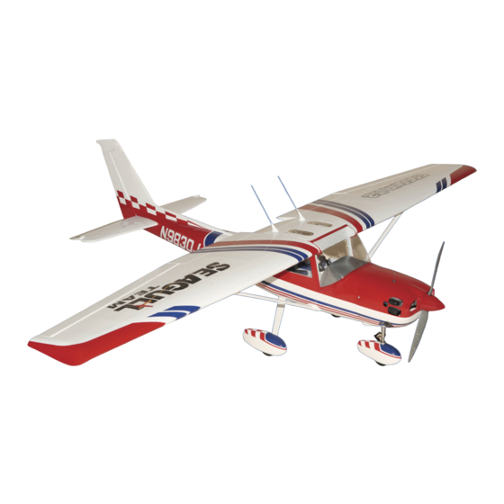
CESSNA 152
MS: 174
ASSEMBLY MANUAL
"Graphics and specifications may change without notice".
Specifications:
Wing span ------------------------------79.9in (203cm).
Wing area -----------------911.4sq.in (58.8sq dm).
Weight ----------------------------------9.9lbs (4.5kg).
Length ------------------------------57.5in (146.0cm).
Engine ------------------ ----0.75-0.91cu.in -2-stroke.
0.91-1.25cu.in -4-stroke.
Radio ------------------- 5 channels with 8 servos.
Electric conversion: optional
1
Advertisement
Table of Contents

Related Manuals for Seagull Models CESSNA 152


Summary of Contents for Seagull Models CESSNA 152
- Page 1 WWW.SEAGULLMODELS.COM CESSNA 152 MS: 174 ASSEMBLY MANUAL “Graphics and specifications may change without notice”. Specifications: Wing span ------------------------------79.9in (203cm). Wing area -----------------911.4sq.in (58.8sq dm). Weight ----------------------------------9.9lbs (4.5kg). Length ------------------------------57.5in (146.0cm). Engine ------------------ ----0.75-0.91cu.in -2-stroke. 0.91-1.25cu.in -4-stroke. Radio ------------------- 5 channels with 8 servos.
-
Page 2: Kit Contents
You will find that most of the work has been done for you already. The motor mount has been fitted and the hinges are pre-installed. Flying the CESSNA 152 is simply a joy. This instruction manual is designed to help you build a great flying earoplane. Please read this manual throughly before starting assembly of your CESSNA 152. -
Page 3: Additional Items Required
WWW.SEAGULLMODELS.COM KIT CONTENTS. HINGING THE FLAP SEA17401 Fuselage SEA17402 Wing Set SEA17403 Tail Set SEA17404 Fiberglass Cowling SEA17405 Main Landing Gear SEA17406 Nose Landing Gear SEA17407 Windshield and Window set SEA17408 Decal SEA17409 Pushrod Set SEA17410 Wing tube SEA17411 Fiberglass Wheel Pants ADDITIONAL ITEMS REQUIRED. -
Page 4: Hinging The Aileron
CESSNA 152 Instruction Manual. HINGING THE AILERON. Note : The control surfaces, including the ai- lerons, elevators, and rudder, are pre- hinged with hinges in stalled, but the hinges are not glued in place. It is im- perative that you properly adhere the hinges in place per the steps that fol- low using a high-quality thin C/A glue. -
Page 5: Hinging The Elevator
WWW.SEAGULLMODELS.COM HINGING THE ELEVATOR. Glue the elevator hinges in place using the same techniques used to hinge the ailerons. 5) Turn the wing panel over and deflect the aileron in the opposite direction from the HINGING THE RUDDER. opposite side. Apply thin C/A glue to each hinge, making sure that the C/A pene- Glue the rudder hinges in place using the trates into both the aileron and wing panel. - Page 6 CESSNA 152 Instruction Manual. INSTALL ELEVATOR CONTROL HORN. Epoxy Aileron control horn. Fiberglass control horn. INSTALL FLAP CONTROL HORN. Install the flap control horn using the same method as same as the aileron control horns. Epoxy Fiberglass control horn. Aileron control horn.
-
Page 7: Installing The S Topper Assembly
WWW.SEAGULLMODELS.COM Epoxy INSTALLING THE S TOPPER ASSEMBLY 1) Using a modeling knife, carefully cut off the rear portion of one of the 3 nylon tubes leaving 1/2” protruding from the rear of the stopper. This will be the fuel pick up tube. Rudder control horn. -
Page 8: Fuel Tank Installation
CESSNA 152 Instruction Manual. Fuel tank. Vent tube. Fuel pick up tube. 8) Use plywood template to hold in place the Fuel fill tube. fuel tank with C/A glue to secure the fuel 3) Carefully bend the second nylon tube up tank inside the fuselage. -
Page 9: Installing The Fuselage Servos
WWW.SEAGULLMODELS.COM Blow through one of the lines to ensure Rudder servo arm. the fuel lines have not become kinked inside the fuel tank compartment. Air should flow through easily. Throttle servo arm. INSTALLING THE FUSELAGE SERVOS. Elevator servo arm. Because the size of servos differ, you may need to adjust the size of the precut opening in the mount. - Page 10 CESSNA 152 Instruction Manual. WHEELS AND WHEEL PANTS. Landing Gear. wheel Pant. 1) Assemble and mounting the landing gear, wheels to the wheel pants as shown inthe fol- C/A glue. lowing pictures. 2) Follow diagram below for wheel pant in- stallation: wheel collar.
-
Page 11: Installing The Main Landing Gear
WWW.SEAGULLMODELS.COM 4 mm INSTALLING THE MAIN LANDING 3) Use a drill to drill the four holes in the GEAR. engine mount rails. 1) The blind nuts for securing the landing 4) On the fire wall has the location for the gear are already mounted inside the fuselage. -
Page 12: Landing Gear Installation
CESSNA 152 Instruction Manual. LANDING GEAR INSTALLATION. A. NOSE GEAR: 1)Locate the items necessary to attach the nose landing gear that are included with your model. Thread locker glue. Thread locker glue. 8) Move the throttle stick to the closed posi- tion and move the carburetor to closed. - Page 13 WWW.SEAGULLMODELS.COM Screw. 4mm hole. Axle. 2)Install landing gear at the top Fuselage. wheel collar. wheel. 13 13...
- Page 14 CESSNA 152 Instruction Manual. Trim and cut. Screw. Trim and cut. 225 mm M3 clevis. M3 lock nut Install lights at the top Cowling Pushrod. COWLING 1) Slide the fiberglass cowl over the engine and line up the back edge of the cowl with Drill hole 4mm.
- Page 15 WWW.SEAGULLMODELS.COM Needle valve Epoxy. Machine screw M3x10mm 3) Install the muffler and muffler extension Because of the size of the cowl, it may be nec- onto the engine and make the cutout in the essary to use a needle valve extension for the cowl for muffler clearance.
- Page 16 CESSNA 152 Instruction Manual. Blind nut. M4x20mm M3x15mm 4) Attach the motor to the front of the electric motor box using four 4mm blind nut, four M3x15mm hex head bolts to se- cure the motor. Please see picture shown. 150mm Balsa stick.
-
Page 17: Installing The Aileron - Flap Servos
WWW.SEAGULLMODELS.COM The propeller should not touch any part of the spinner cone. If it does, use a sharp modeling knife and carefully trim away the spinner cone where the propeller comes in Battery. contact with it. 5) Attach the speed control to the side of the motor box using two-sided tape and tie wraps. - Page 18 CESSNA 152 Instruction Manual. 2) Place the servo between the mounting 6) Secure the servo to the aileron hatch using blocks and space it from the hatch. Use a Phillips screwdriver and the screws provided pencil to mark the mounting hole locations with the servo.
- Page 19 WWW.SEAGULLMODELS.COM AILERON PUSHROD HORN INSTALLATION. 100mm. M3 clevis. M3 lock nut. Wing M2 lock nut. Aileron INSTALLING THE FLAP SERVO. 9) Set the aileron hatch in place and use a Phillips screw driver to install it with four Repeat the procedure for the aileron servo. wood screws.
-
Page 20: Installing The Horizontal Sta- Bilizer
CESSNA 152 Instruction Manual. 90mm. M3 clevis. M3 lock nut. 3) Slide the stabilizer into place in the precut Wing M2 lock nut. slot in the rear of the fuselage. The stabilizer should be pushed firmly against the front of the slot. - Page 21 WWW.SEAGULLMODELS.COM Trim and cut When cutting through the covering to INSTALLING VERTICAL FIN. remove it, cut with only enough pressure to only cut through the covering itself. Cutting into the balsa structure may weaken it. 6) Using a modeling knife, carefully remove the covering that overlaps the stabilizer mounting platform sides in the fuselage.
- Page 22 CESSNA 152 Instruction Manual. Fill epoxy 3) Slide the vertical stabilizer back in place. ELEVATOR PUSHROD HORN INSTAL- Using a triangle, check to ensure that the ver- LATION. tical stabilizer is aligned 90º to the horizontal stabilizer. 1) Install the elevator control horn using the same method as with the aileron control horns.
- Page 23 WWW.SEAGULLMODELS.COM 810mm. 810mm. 820 mm Rudder pushrod. M2 clevis. M2 clevis. M2 lock nut. M2 lock nut. INSTALLATION PILOT AND CANOPY. Elevator pushrod. 1) Locate items necessary to install pilot and canopy. Elevator pushrod. 2) A scale pilot is included with this ARF. The Seagull Pilot included fitting well to the cockpit.
-
Page 24: Apply The Decals
CESSNA 152 Instruction Manual. APPLY THE DECALS. 1) If all the decals are precut and ready to stick. Please be certain the model is clean and free from oily fingerprints and dust. Position decal on the model where desired, using the photos on the box and aid in their location. - Page 25 WWW.SEAGULLMODELS.COM Installation Antenas. ATTACHMENT WING-FUSELAGE. Attach the aluminium tube into fuselage. Antennas. Wing tube. Insert two wing panels as pictures below. INSTALLATION WING- FUSELAGE STRUTS. Wing bolt. Remove covering. Wing.
- Page 26 CESSNA 152 Instruction Manual. Wing. M3x25mm. Wing. Fuselage. M3x25mm. BALANCING. 1) It is critical that your airplane be bal- anced correctly. Improper balance will cause your plane to lose control and crash. THE CENTER OF GRAVITY IS LOCATED 110 MM BACK FROM THE LEADING EDGE OF THE WING AT THE WING ROOT.
-
Page 27: Control Throws
WWW.SEAGULLMODELS.COM 3) Turn the airplane upside down. Place your fingers on the masking tape and 110MM carefully lift the plane . Accurately mark the balance point on the top of the wing on both sides of the fuse- lage. The balance point is located 110 mm back from the leading edge of the wing at the wing root. -
Page 28: Flight Preparation
A) Plug in your radio system per the 2) Check every bolt and every glue joint in manufacturer’s instructions and turn eve- the CESSNA 152 to ensure that everything is rything on. tight and well bonded. B) Check the elevator first. Pull back on the elevator stick. - Page 29 WWW.SEAGULLMODELS.COM FOR USA MARKET ONLY. Safety,Precautions and Warnings As the user of this product, you are solely responsible for operating it in a manner that does not endanger yourself and others or result in damage to the product or the property of others. Carefully follow the direc- tions and warnings for this and any optional support equipment (chargers, rechargeable battery packs, etc.) that you use.
- Page 30 CESSNA 152 Instruction Manual. If you as the Purchaser or user are not prepared to accept the liability associated with the use of this Product, you are advised to return this Product immediately in new and unused condition to the place of purchase.
Need help?
Do you have a question about the CESSNA 152 and is the answer not in the manual?
Questions and answers