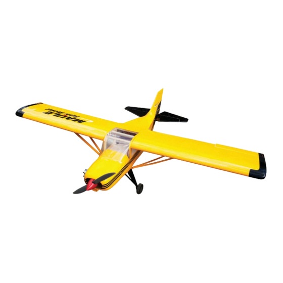
Seagull Models MAULE SUPER ROCKET 15CC Assembly Manual
Hide thumbs
Also See for MAULE SUPER ROCKET 15CC:
- Assembly manual (34 pages) ,
- Assembly manual (35 pages)
Table of Contents
Advertisement
Quick Links
WWW.SEAGULLMODELS.COM
A S S E M B L Y M A N U A L
" Graphics and specifications may change without notice " .
Code: SEA232
Specifications:
Wingspan---------------70.9 in (180 cm).
Wing area---------------810.3 sq.in (52.3 sq.dm).
Weight-------------------9.0 lbs (4.1 kg).
Length-------------------47.4 in (120.5 cm).
Engine-------------------10cc - 15cc.
Glow engine------------.61-.91 - 2 stroke
Motor size---------------Power 60
Radio--------------------6 channels with 8 servos.
Electric conversion: Optional.
www.seagullmodels.com
1
Advertisement
Table of Contents

Subscribe to Our Youtube Channel
Related Manuals for Seagull Models MAULE SUPER ROCKET 15CC


Summary of Contents for Seagull Models MAULE SUPER ROCKET 15CC
- Page 1 WWW.SEAGULLMODELS.COM A S S E M B L Y M A N U A L “ Graphics and specifications may change without notice ” . Code: SEA232 Specifications: Wingspan---------------70.9 in (180 cm). Wing area---------------810.3 sq.in (52.3 sq.dm). Weight-------------------9.0 lbs (4.1 kg). Length-------------------47.4 in (120.5 cm).
-
Page 2: Kit Contents
Instruction Manual. INTRODUCTION. Thank you for choosing the MAULE SUPER ROCKET ARF by SEAGULL MODELS COMPANY LTD,. The MAULE SUPER ROCKET was designed with the intermediate/ advanced sport flyer in mind. It is a semi scale airplane which is easy to fly and quick to assemble. -
Page 3: Additional Items Required
WWW.SEAGULLMODELS.COM HINGING THE FLAP. KIT CONTENTS. SEA232 MAULE SUPER ROCKET SEA23201 Fuselage SEA23202 Wing set SEA23203 Tail set SEA23204 Canopy SEA23205 Pilot SEA23206 Cowling SEA23207 Aluminum wing tube ADDITIONAL ITEMS REQUIRED. M2x10mm 10-15cc gasoline engine. � .61-.91 glow engine. � Power 60 size motor. -
Page 4: Hinging The Aileron
Maule SUPER ROCKET Instruction Manual. Hinge. 3) Slide the wing panel on the aileron until there is only a slight gap. The hinge is now centered on the wing panel and aileron. Re- move the T-pins and snug the aileron against the wing panel. -
Page 5: Hinging The Rudder
WWW.SEAGULLMODELS.COM 5) Turn the wing panel over and deflect the HINGING THE RUDDER. aileron in the opposite direction from the opposite side. Apply thin C/A glue to each Glue the top two rudder hinges in place hinge, making sure that the C/A penetrates using the same techniques used to hinge into both the aileron and wing panel. - Page 6 Maule SUPER ROCKET Instruction Manual. INSTALL ELEVATOR CONTROL HORN. Epoxy. Fiberglass control horn. Aileron control horn. INSTALL FLAP CONTROL HORN. Install the flap control horn using the same method as same as the aileron con- trol horns. Epoxy. Elevator fiberglass control horn. Fiberglass control horn.
-
Page 7: Installing The Fuselage Servos
WWW.SEAGULLMODELS.COM Throttle servo. Epoxy. The back of fuselage. THROTTLE SERVO ARM INSTALLATION. Install adjustable servo connector in the servo arm as same as picture below: Loctite secure. Adjustable servo connector. Rudder fiberglass control horn. INSTALLING THE FUSELAGE SERVOS. Servo arm. Because the size of servos differ, you may need to adjust the size of the precut opening in the mount. - Page 8 Maule SUPER ROCKET Instruction Manual. INSTALLING THE RECEIVER SWITCH. Install the switch into the precut hole in the side, in the fuselage. 3/32” Hole. Switch. INSTALLING THE STOPPER ASSEMBLY. 1) Using a modeling knife, carefully cut off the rear portion of one of the 3 nylon tubes leaving 1/2”...
-
Page 9: Fuel Tank Installation
WWW.SEAGULLMODELS.COM Vent tube. Fuel pick up tube. Fuel fill tube. 8) Use plywood template to hold in place the fuel tank with C/A glue to secure the fuel 3) Carefully bend the second nylon tube up tank inside the fuselage. at a 45º... -
Page 10: Mounting The Engine
Maule SUPER ROCKET Instruction Manual. Vent tube. Fuel fill tube. Thread locker glue. Fuel pick up tube. 9) Connect the lines from the tank to the en- MOUNTING THE ENGINE. gine and muffler. The vent line will connect to the muffler and the line from the clunk to 1) Position the engine with the drive the carburetor. - Page 11 WWW.SEAGULLMODELS.COM Machine screw M4x30mm 4) On the fire wall has the location for the throttle pushrod tube (pre-drill). 8) Reinstall the servo horn by sliding the connector over the pushrod wire. Cent- 5) Slide the pushrod tube in the firewall er the throttle stick and trim and install and guide it through the fuel tank mount.
- Page 12 Maule SUPER ROCKET Instruction Manual. Cut. Because of the size of the cowl, it may be nec- essary to use a needle valve extension for the high speed needle valve. Make this out of suf- COWLING. ficient length 1.5mm wire and install it into the end of the needle valve.
- Page 13 WWW.SEAGULLMODELS.COM - Motor: 50mm 310-500 kV - Propeller: 14x10 ~ 15x10 - ESC: 60A - Lipo Batteries: 5-6 cell 4000-5000mAh 3) Attach the electric motor box to the firewall suitable with the cross lines drawn on the electric motor box and firewall.
- Page 14 Maule SUPER ROCKET Instruction Manual. Epoxy 145 mm Balsa stick. 4 mm Epoxy 5) Attach the speed control to the side of the motor box using two-sided tape and tie wraps. Connect the appropriate leads from the speed control to the mo- tor.
-
Page 15: Installing The Aileron Servos
WWW.SEAGULLMODELS.COM INSTALLING THE AILERON SERVOS. Battery. INSTALLING THE SPINNER. Install the spinner backplate, propeller Servos Small weight and spinner cone. Thread Because the size of servos differ, you may need to adjust the size of the precut opening in the mount. The notch in the sides of the mount allow the servo lead to pass through. - Page 16 Maule SUPER ROCKET Instruction Manual. 3) Use drill bit in a pin vise to drill the mouting holes in the blocks. C/A glue 8) Remove the string from the wing at the servo location and use the tape to at- tach it to the servo extension lead.
-
Page 17: Aileron Pushrod Installation
WWW.SEAGULLMODELS.COM INSTALLING THE FLAP SERVO. Repeat the procedure for the flap servo. AILERON PUSHROD INSTALLATION. Please see below pictures. 9) Set the aileron hatch in place and use a Phillips screw driver to install it with four wood screws. Use a felt tip pen to mark the wire where M2x10mm it crosses the hole. - Page 18 Maule SUPER ROCKET Instruction Manual. INSTALLING THE MAIN LANDING GEAR TO FUSELAGE. Bend at the mark M2 lock nut. Metal clevis. Snap keeper. Servo arm. 1) The blind nuts for securing the land- Snap keeper. ing gear are already mounted inside the fuselage.
-
Page 19: Installing Wheels
WWW.SEAGULLMODELS.COM M4x20mm INSTALLING WHEELS. Collar. Collar. Collar. -
Page 20: Installing The Horizontal Stabilizer
Maule SUPER ROCKET Instruction Manual. 3) Slide the stabilizer into place in the precut slot in the rear of the fuselage. The stabilizer should be pushed firmly against the front of the slot. M4x20mm INSTALLING THE HORIZONTAL STABILIZER. 4) With the stabilizer held firmly in place, 1) Using a ruler and a pen, locate the cen- terline of the horizontal stabilizer, at the use a pen and draw lines onto the stabi-... -
Page 21: Installing Vertical Stabilizer
WWW.SEAGULLMODELS.COM 6) Using a modeling knife, carefully re- INSTALLING VERTICAL STABILIZER move the covering that overlaps the sta- bilizer mounting platform sides in the fuselage. Remove the covering from both the top and the bottom of the platform sides. Epoxy 1) Using a modeling knife, remove the covering from over the precut hinge slot 7) When you are sure that everything is... -
Page 22: Elevator Pushrod Installation
Maule SUPER ROCKET Instruction Manual. 5) When you are sure that everything is aligned correctly, mix up a generous amount of Flash 30 Minute Epoxy. Ap- ply a thin layer to the mounting slot and to bottom of the vertical stabilizer mounting area. -
Page 23: Rudder Pushrod Installation
WWW.SEAGULLMODELS.COM 3) Thread one clevis and M2 lock nut on Nylon Snap Keeper. to each elevator control rod. Thread the horns on until they are flush with the ends of the control rods. 4) Elevator and rudder pushrods assem- bly as pictures below. M2 clevis. -
Page 24: Mounting The Tail Wheel
Maule SUPER ROCKET Instruction Manual. MOUNTING THE TAIL WHEEL. Pen. Locate items necessary to install tail wheel. 3x25 mm. Aluminum tail landing gear. 3 x 20mm. Springs... - Page 25 WWW.SEAGULLMODELS.COM 3) Position the pilot figure on the cano- py floor as shown. Use epoxy to glue the base of the pilot figure, please see pic- tures as shown. Epoxy. INSTALLATION PILOT AND CANOPY. 1) Locate items necessary to install pilot, seats.
-
Page 26: Apply The Decals
Maule SUPER ROCKET Instruction Manual. APPLY THE DECALS. 1) If all the decals are precut and ready to stick. Please be certain the model is clean and free from oily fingerprints and dust. Position decal on the model where de- sired, using the photos on the box and aid 4x10mm in their location. - Page 27 WWW.SEAGULLMODELS.COM 4x15mm 4x15mm 4x10mm INSTALLATION WING- FUSELAGE STRUTS. M3 clevis. 3x12mm...
- Page 28 Maule SUPER ROCKET Instruction Manual. 4x20mm OPTIONAL FLOAT FOR MAULE SUPER ROCKET (SEA232F ). 1) Install Struts onto floats. 2) Install Water Rudder.
- Page 29 WWW.SEAGULLMODELS.COM Drill hole. 3x25mm Collar.
- Page 30 Maule SUPER ROCKET Instruction Manual. 3) Attach float to fuselage. 4x20mm 4) Install water rudder control bellcrank to fuselage .
- Page 31 WWW.SEAGULLMODELS.COM 5) Install water rudder control cables. Bend at the mark M2 lock nut. Metal clevis. Snap keeper.
- Page 32 Maule SUPER ROCKET Instruction Manual. 3) With the model upright, place your fingers on the masking tape and carefully lift the plane. This is the point at which your model should balance for your first flights. Later, you may wish to experi- ment by shifting the balance up to 10mm forward or back to change the flying characteristics.
-
Page 33: Control Throws
WWW.SEAGULLMODELS.COM CONTROL THROWS. Ailerons: 70mm Rudder: High Rate : High Rate : Up : 25 mm Right : 30 mm Down : 25 mm Left : 30 mm Low Rate : Low Rate : Up : 15 mm Right : 20 mm Down : 15 mm Left : 20 mm Elevator:... -
Page 34: Flight Preparation
If it does not, flip the servo reversing excessive vibration which could lead switch on your transmitter to change to engine and/or airframe failure. the direction. We wish you many safe and enjoyable flights with your MAULE SUPER ROCKET 15cc.
Need help?
Do you have a question about the MAULE SUPER ROCKET 15CC and is the answer not in the manual?
Questions and answers