Table of Contents
Advertisement
Quick Links
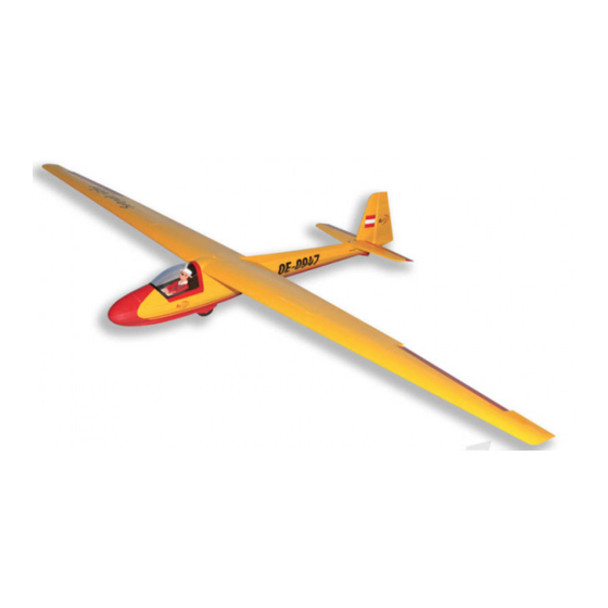
(Glider)
MS:137
ASSEMBLY MANUAL
"Graphics and specifications may change without notice".
Specifications:
Wing span -------------------------------------------- 118.1in (300cm).
Wing area ---------------------------------------- 899sq.in (58sq dm).
Weight ---------------------------------------------------- 6.2lbs (2.8kg).
Length -------------------------------------------------- 57.1in (145cm).
Radio --------------------------------------------------------- 6 channels.
Servo --------------------------------------------- 4 MN48 mini servos.
3 servos flying skill level intermediate/advanced.
Advertisement
Table of Contents

Related Manuals for Seagull Models KA8-B


Summary of Contents for Seagull Models KA8-B
- Page 1 (Glider) MS:137 ASSEMBLY MANUAL “Graphics and specifications may change without notice”. Specifications: Wing span -------------------------------------------- 118.1in (300cm). Wing area ---------------------------------------- 899sq.in (58sq dm). Weight ---------------------------------------------------- 6.2lbs (2.8kg). Length -------------------------------------------------- 57.1in (145cm). Radio --------------------------------------------------------- 6 channels. Servo --------------------------------------------- 4 MN48 mini servos. 3 servos flying skill level intermediate/advanced.
-
Page 2: Parts Listing
ARTF , yet the design allows the aeroplane to be kept light. You will find that most of the work has been done for you already. The pushrods are pre-made to the correct lengths, the motor mount has been fitted and the hinges are pre-installed and pinned for security. Flying the KA8-B is simply a joy. -
Page 3: Hinging The Rudder
Instruction Manual. HINGING THE RUDDER . Note: The control surfaces, including the ailerons, elevators, and rudder, are prehinged with hinges installed, but the hinges are not glued in place. It is imperative that you properly Hinge. adhere the hinges in place per the steps that follow using a high-quality thin C/A glue. -
Page 4: Hinging The Elevator
Instruction Manual. KA8-B HINGING THE ELEVATOR . 5) Turn the wing panel over and deflect the aileron in the opposite direction from the opposite side. Apply thin C/A glue to each hinge, making sure that the C/A penetrates into both the aileron and wing panel. - Page 5 Instruction Manual. INSTALL THE AILERON CONTROL HORN . 1) Locate the hardware necessary to install the control horns for the ailerons. 3x35mm. 2 sets. 2) Position the control horn on the bottom of the aileron. You will see pre-drill hole 6mm for the horn mounting screw on the aileron.
-
Page 6: Servo Arm Installation
Instruction Manual. KA8-B Elevator control horn. INSTALLING THE FUSELAGE SERVO. Because the size of servos differ, you may need to adjust the size of the precut open- ing in the mount. The notch in the sides of the mount allow the servo lead to pass through. -
Page 7: Aileron Servo Installation
Instruction Manual. AILERON SERVO INSTALLATION. Rudder servo arm. Servos. Throttle servo arm. Elevator servo arm. Because the size of servos differ, you may need to adjust the size of the precut open- INSTALLING THE SWITCH. ing in the mount. The notch in the sides of the mount allow the servo lead to pass through. -
Page 8: Flap Servo Installation
Instruction Manual. KA8-B FLAP SERVO INSTALLATION. Flap servo. Wing. Aileron servo. Wing rib. M2x6mm. M2x6mm. Small weight. String. Attach the string to the servo lead and carefully thread it though the wing. AILERON PUSHROD HORN INSTALLATION Cut. Aileron servo. Metal clevis. - Page 9 Instruction Manual. C/A glue. Repeat the procedure for the other aileron servo. AIRBREAKES PUSHROD CONTROL HORN INSTALLATION. M2x6mm. C/A glue.
-
Page 10: Elevator Pushrod Installation
Instruction Manual. KA8-B ELEVATOR PUSHROD INSTALLATION. 678mm. Cut. THE HORIZONTAL STABILIZER INSTALLATION. M3x30mm. M3x30mm. - Page 11 Instruction Manual. Cut. Pen. Snap keeper.
-
Page 12: Rudder Pushrod
Instruction Manual. KA8-B RUDDER PUSHROD. Metal clevis. M2 lock nut. Snap keeper. Servo arm. Snap keeper. M2x12mm. Pen. Cut. -
Page 13: Servo Installation
Instruction Manual. Cut. SERVO INSTALLATION The tow hook. C/A glue. The above is the tow hook position. C/A glue. Cut. -
Page 14: Installing The Receiver And Battery
Instruction Manual. KA8-B INSTALLING THE RECEIVER AND BATTERY. 1) Plug the five servo leads and the switch lead into the receiver. Plug the battery pack lead into the switch also. 2) Wrap the receiver and battery pack in Wing bolt. -
Page 15: Control Throws
Instruction Manual. Accurately mark the balance point on the top of the wing on both sides of the fuselage. The balance point is located 60 mm back from the leading edge of the wing at the wing root. This is the balance point at which your model should balance for your first flights. -
Page 16: Flight Preparation
B) Plug in your radio system per the 2) Check every bolt and every glue joint manufacture’s instructions and turn every thing in the KA8-B to ensure that everything is tight and well bonded. C) Check the elevator first. Pull back on the elevator stick.
Need help?
Do you have a question about the KA8-B and is the answer not in the manual?
Questions and answers