Table of Contents
Advertisement
?
MS:169
ASSEMBLY MANUAL
"Graphics and specifications may change without notice".
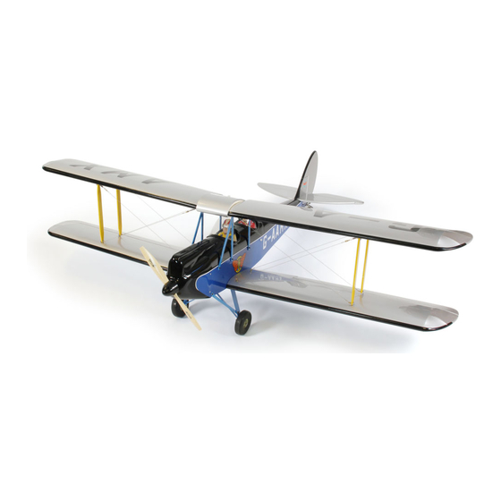
Specifications:
Wing span ------------------------------66.9in (170cm).
Wing area -----------------764.2sq.in (49.3sq dm).
Weight ------------------------10.6lbs (4.8kg).
Length ------------------------------58.7in (149.0cm).
Engine ------------------ 0.75-0.91cu.in ----2-stroke.
Engine ------------------ 0.91-1.10cu.in ----4-stroke.
Radio -------------------4 channels with 6 servos.
Electric conversion: optional
Flying skill level Advanced/Intermediate.
Advertisement
Table of Contents

Subscribe to Our Youtube Channel
Related Manuals for Seagull Models GISPY MOTH


Summary of Contents for Seagull Models GISPY MOTH
- Page 1 MS:169 ASSEMBLY MANUAL “Graphics and specifications may change without notice”. Specifications: Wing span ------------------------------66.9in (170cm). Wing area -----------------764.2sq.in (49.3sq dm). Weight ------------------------10.6lbs (4.8kg). Length ------------------------------58.7in (149.0cm). Engine ------------------ 0.75-0.91cu.in ----2-stroke. Engine ------------------ 0.91-1.10cu.in ----4-stroke. Radio -------------------4 channels with 6 servos. Electric conversion: optional Flying skill level Advanced/Intermediate.
-
Page 2: Kit Contents
. Flying the GISPY MOTH is simply a joy. This instruction manual is designed to help you build a great flying aeroplane. Please read this manual thoroughly before starting assembly of your GISPY MOTH . Use the parts listing below to identify all parts. -
Page 3: Hinging The Aileron
www.seagullmodels.com HINGING THE AILERON . CONTENTS.TS Note: The control surfaces, including the Fuselage ailerons, elevators, and rudder, are Upper Wing Set Lower Wing Set prehinged with hinges installed, but Tail Set the hinges are not glued in place. It Cowling is imperative that you properly Main Landing Gear adhere the hinges in place per the... -
Page 4: Hinging The Elevator
Instruction Manual. GISPY MOTH. Hinge. 5) Turn the wing panel over and deflect the 4) Deflect the aileron and completely aileron in the opposite direction from the saturate each hinge with thin C/A glue. The opposite side. Apply thin C/A glue to each... -
Page 5: Hinging The Rudder
www.seagullmodels.com HINGING THE RUDDER. INSTALL ELEVATOR CONTROL HORN. Glue the rudder hinges in place using the Install the elevator control horn using the same method as same as the aileron control same techniques used to hinge the ailerons. horns. Hinge. Fiberglass control horn Position the Control horn on the Aileron and use 30-minute Epoxy... -
Page 6: Installing The Stopper Assembly
Instruction Manual. GISPY MOTH. Epoxy. INSTALLING THE STOPPER ASSEMBLY. Rudder control horn. 1) Using a modeling knife, carefully cut off the rear portion of one of the 3 nylon tubes leaving 1/2” protruding from the rear of the stopper. This will be the fuel pick up tube. -
Page 7: Fuel Tank Installation
www.seagullmodels.com 7) Slide the fuel tank into the fuselage. Guide the lines from the tank through the hole in the firewall. Fuel tank. Vent tube. Fuel pick up tube. Fuel fill tube. M3x10mm. 8) Use plywood template to hold in place 3) Carefully bend the second nylon tube the fuel tank with C/A glue to secure the fuel up at a 45º... -
Page 8: Installing The Fuselage Servos
Instruction Manual. GISPY MOTH. 3/ 32” Hole. Blow through one of the lines to en- sure the fuel lines have not become kinked inside the fuel tank compartment. Air should flow through easily. INSTALLING THE FUSELAGE SERVOS. Because the size of servos differ, you may need to adjust the size of the precut open- ing in the mount. - Page 9 www.seagullmodels.com 6) Connect the Z-bend in the 450mm throttle 4mm. pushrod to the outer hole of the carburetor arm. 7) Slide the throttle pushrod wire into the tube. Position the engine between the mounts. Use four M4x30mm machine screws to secure the engine to the mount as shown.
- Page 10 Instruction Manual. GISPY MOTH. WHEEL AND WHEEL PANTS M4x20mm. INSTALLATION. 1) Locate the items neccessary to install the wheel and wheel pants to the landing gear as shown. M4x10mm. 2)Attach the Landing gear struts to the fuselage. M3x10mm. M4x20mm. M3x10mm.
- Page 11 www.seagullmodels.com COWLING. 1)Slide the fiberglass cowl over the engine and line up the back edge of the cowl with the marks you made on the fuselage then trim and cut as shown. Trim and cut. Trim and cut. Trim and cut.
- Page 12 Instruction Manual. GISPY MOTH. Because of the size of the cowl, it may be nec- essary to use a needle valve extension for the high speed needle valve. Make this out of suf- ficient length 1.5mm wire and install it into the end of the needle valve.
- Page 13 www.seagullmodels.com 4mm. Blind nut. M4x20mm. 3) Attach the motor to the front of the electric motor box using four 4mm blind nut, four M3x15mm hex head bolts to secure the motor. Please see picture shown. M3x15mm. Epoxy. 4mm. 140mm.
-
Page 14: Installing The Propeller
Instruction Manual. GISPY MOTH. INSTALLING THE PROPELLER. Balsa stick. Epoxy. Electric motor. Battery. 5) Attach the speed control to the side of the INSTALLING THE AILERON - FLAP SERVOS. motor box using two-sided tape and tie wraps. Connect the appropriate leads from the speed control to the motor. - Page 15 www.seagullmodels.com 5) Use dental floss to secure the connection Because the size of servos differ, you so they cannot become unplugged. may need to adjust the size of the precut open- ing in the mount. The notch in the sides of the mount allow the servo lead to pass through.
-
Page 16: Installing The Horizontal Stabilizer
Instruction Manual. GISPY MOTH. AILERON PUSHROD HORN INSTALLATION 50mm. M3 clevis. M3 lock nut. 80mm. Wing. M3 lock nut. Aileron. 9) Set the aileron hatch in place and use a INSTALLING THE HORIZONTAL STABILIZER. Phillips screw driver to install it with four wood screws. - Page 17 www.seagullmodels.com Draw center line. Pen. 2) Using a modeling knife, carefully remove 5) Remove the stabilizer. Using the lines you just drew as a guide, carefully remove the the covering at mounting slot of horizontal sta- covering from between them using a model- bilizer ( both side of fuselage).
- Page 18 Instruction Manual. GISPY MOTH. Fill epoxy. Fill epoxy. 3) Slide the vertical stabilizer back in INSTALLING VERITICAL FIN. place. Using a triangle, check to ensure that the vertical stabilizer is aligned 90º to the hori- zontal stabilizer. Vertical Stabilizer. Horizontal 90º...
-
Page 19: Installation
www.seagullmodels.com 4) When you are sure that everything is 3) Thread one clevis and M3 lock nut on aligned correctly, mix up a generous amount of to each elevator control rod. Thread the horns Flash 30 Minute Epoxy. Apply a thin layer to the on until they are flush with the ends of the con- mounting slot and to bottom of the vertical sta- trol rods. - Page 20 Instruction Manual. GISPY MOTH. MOUNTING THE TALI WHEEL. 1) Locate the items for this section of the manual. INSTALLATION PILOT AND CANOPY. 1) Locate items necessary to install pilot, cockpit panel, and canopy. 3x15mm. Aluminum tail landing gear. 2) A scale pilot is included with this ARF. The Seagull Pilot included fitting well to the cockpit.
-
Page 21: Cabane Strut Installation
www.seagullmodels.com 2) Wrap the receiver and battery pack in the protective foam rubber to protect them from vibration. 3) Route the antenna in the antenna tube inside the fuselage and secure it to the bot- tom of fuselage using a plastic tape. Receiver. - Page 22 Instruction Manual. GISPY MOTH. Wing tube. M3x10mm. Insert two lower wing panels as pictures below. M3x10mm. 3) Install the dummy fuel tank. Wing bolt. Insert two upper wing panels as pictures below. M3x10mm. ATTACHMENT WING-FUSELAGE. Attach the aluminium tube into fuselage.
- Page 23 www.seagullmodels.com Wing bolt. M3x20mm. INSTALLATION WING STRUTS. 3)Repeat steps to prepare the remaining wing panel for installation and use pliers to bend four of the brass tabs at a slight 1)Locate the items for this section of the angle.Make the bend slightly biased toward the manual.
-
Page 24: Installation Cable
Instruction Manual. GISPY MOTH. M3x20mm. INSTALLATION CABLE. 1)Prepare one end of the cable by attaching a cable end using a copper crimp. Thread a nut, then a clevis, on the cable end as shown. Prepare only one end of each cable at this time. - Page 25 www.seagullmodels.com Accurately mark the balance point on the top 4)Use the transport frames to transport the of the wing on both sides of the fuselage. The wing panels once they are removed from balance point is located 100 mm back from the leading edge of the wing at the wing root.
-
Page 26: Control Throws
Instruction Manual. GISPY MOTH. CONTROL THROWS. Ailerons: Rudder: High Rate : High Rate : Up : 25 mm Right : 40 mm Down : 25 mm Left : 40 mm Low Rate : Low Rate : Up : 15 mm... -
Page 27: Flight Preparation
If it does not, flip the servo re- versing switch on your transmitter to change the direction. We wish you many safe and enjoyable flights with your GISPY MOTH.
Need help?
Do you have a question about the GISPY MOTH and is the answer not in the manual?
Questions and answers