Table of Contents
Advertisement
Quick Links
Code : SEA 313
ASSEMBLY MANUAL
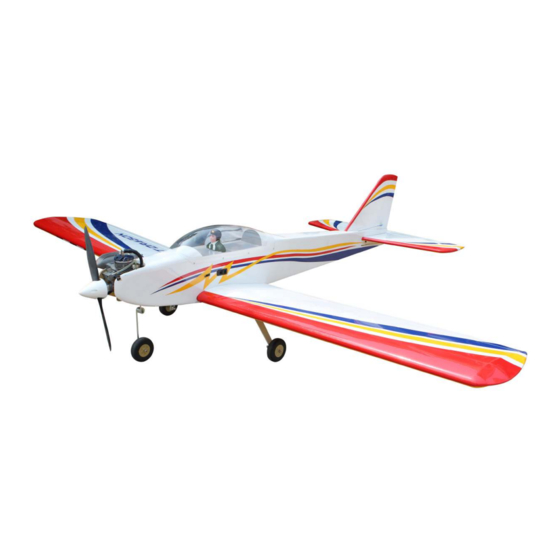
Speciications:
Wingspan------------------- 206 cm------------------- 81 inches.
Length----------------------- 146 cm------------------- 57.5 inches.
Wing area------------------- 62.7sq.dm--------------- 971.2 sq.in.
Weight----------------------- 4.5 kg-------------------- 9.9 lbs.
Engine----------------------- 15cc.
Motor------------------------ Motor 90 / 85A / 6S-8S / 1800watt.
Radio------------------------ 6 channels 7 servos.
1
Advertisement
Table of Contents

Subscribe to Our Youtube Channel
Related Manuals for Seagull Models TEMPEST DRAGON 15cc ARF


Summary of Contents for Seagull Models TEMPEST DRAGON 15cc ARF
- Page 1 Code : SEA 313 ASSEMBLY MANUAL Speciications: Wingspan------------------- 206 cm------------------- 81 inches. Length----------------------- 146 cm------------------- 57.5 inches. Wing area------------------- 62.7sq.dm--------------- 971.2 sq.in. Weight----------------------- 4.5 kg-------------------- 9.9 lbs. Engine----------------------- 15cc. Motor------------------------ Motor 90 / 85A / 6S-8S / 1800watt. Radio------------------------ 6 channels 7 servos.
-
Page 2: Kit Contents
Flying the TEMPEST DRAGON 15cc ARF is simply a joy. his instruction manual is designed to help you build a great lying aeroplane. Please read this manual throughly before starting assembly of your TEMPEST DRAGON 15cc ARF Use the parts listing below to indentify all parts. -
Page 3: Additional Items Required
HINGING THE FLAP KIT CONTENTS TEMPEST DRAGON 15cc ARF SEA313 Note : he control surfaces, including the ailer- ons, elevators, and rudder, are prehinged with hinges installed, but the hinges are not glued in 1. Fuselage place. It is imperative that you properly adhere 2. -
Page 4: Hinging The Aileron
TEMPEST DRAGON 15cc ARF Instruction Manual. Delect the lap and completely saturate Repeat this process with the other wing each hinge with thin C/A glue. he lap front panel, securely hinging the lap in place. surface should lightly contact the wing dur- Ater both lap are securely hinged, irmly ing this procedure. - Page 5 Remove each hinge from the wing panel and aileron and place a T-pin in the center of each hinge. Slide each hinge into the wing CA glue panel until the T-pin is snug against the wing panel. his will help ensure an equal amount of hinge is on either side of the hinge line when the aileron is mounted to the aileron.
- Page 6 TEMPEST DRAGON 15cc ARF Instruction Manual. Ater both ailerons are securely hinged, irmly grasp the wing panel and aileron to make sure the hinges are securely glued and cannot be pulled out. Do this by carefully ap- plying medium pressure, trying to separate the aileron from the wing panel.
-
Page 7: Installing The Aileron Servos
INSTALLING THE AILERON SERVOS Epoxy Apply epoxy to the area of the control horns that ist into the slots. Use enough epoxy so the control horns will be fully bonded to the ied surfaces. Epoxy Mininum servo spec. Before the epoxy fully cures, remove Torque : 54 oz-in (3.9 kg-cm) @ 4.8V;... - Page 8 TEMPEST DRAGON 15cc ARF Instruction Manual. Using a small weight (Weighted fuel pickup works well) and thread, feed the string through the wing as indicated. Reinstall the servo into the servo mount and secure the servo inplace using the wood screws provided with you radio system.
-
Page 9: Aileron Pushrod Installation
Make a 90-degree bend at the mark and AILERON PUSHROD INSTALLATION cut of the excess wire leaving 8mm past the bend. Please study images below. Use a felt tip pen to mark the wire where it crosses the hole. Use a pair of pliers to put a shrp 90-degree bend in the wire at the mark. - Page 10 TEMPEST DRAGON 15cc ARF Instruction Manual. he blind nuts for securing the landing gear are already mounted inside the wing set. Using the hardware provided, mount the main landing gear to the wing set. Place the wing set inverted on the work bench in a suitable stand.
-
Page 12: Nose Gear Installation
TEMPEST DRAGON 15cc ARF Instruction Manual. NOSE GEAR INSTALLATION Please see Images below: M4x15mm M3x4mm... - Page 14 TEMPEST DRAGON 15cc ARF Instruction Manual. INSTALLING THE FUSELAGE SERVOS Because the size of servos difer, you may need to adjust the size of the precut opening in the mount. he notch in the sides of the mount allow the servo lead to pass through.
-
Page 15: Installing The Stopper Assembly
INSTALLING THE RECEIVER SWITCH Install the switch into the precut hole in the side, in the fuselage. 3/32” Hole. Switch INSTALLING THE STOPPER ASSEMBLY Using a modeling knife, carefully cut of the rear portion of one of the 3 nylon Trim and cut tubes leaving 1/2”... -
Page 16: Fuel Tank Installation
TEMPEST DRAGON 15cc ARF Instruction Manual. Slide the fuel tank into the fuselage. Guide Vent tube the lines from the tank through the hole in the iewall. Use plywood template to hold in place the Fuel pick up tube Fuel ill tube fuel tank with C/A glue to secure the fuel- tank inside the fuselage. -
Page 17: Mounting The Engine
Vent tube Fuel pick up tube Fuel ill tube Position the engine with the drive wash- Connect the lines from the tank to the er (135mm) forward of the irewall as engine and muler. he vent line will shown. connect to the muler and the line from the clunk tothe carburetor. - Page 18 TEMPEST DRAGON 15cc ARF Instruction Manual. Pushrod wire On the ie wall has the location for the throttle pusshrod tube (pre-drill). Slide the pushrod tube in the iewall and guide it through the fuel tank mount. Use medium C/A to glue the tube to the ie- wall and the fuel tank mount.
-
Page 19: Installing The Spinner
ELECTRIC POWER CONVERSION Locate the items neccessary to install the electric power conversion included with your model. Model size: .46-.52 size models - Motor: 35mm 830 rev per volt - Propeller: 12x6 ~ 13x6 - ESC: 60A - Lipo Batteries: 4 cell 4200mA INSTALLING THE SPINNER Attach the electric motor box to the ire- wall suitable with the cross lines drawn on... - Page 20 TEMPEST DRAGON 15cc ARF Instruction Manual. M4x20mm Attach the motor to the front of the electric motor box using four 4mm blind nut, four M4x16mm hex head bolts to se- cure the motor. Please see picture shown. Nut M4 M4x16mm Locate the plywood battery tray to the fuselage.
- Page 21 M3x12mm 135mm Attach the speed control to the sidem of the motor box using two-sided tape Battery and tie wraps. Connect the appropriate leads from the speed control to the mo- tor. Make sure the leads will not interfere with the operation of the motor. Tie wraps Speed control...
- Page 22 TEMPEST DRAGON 15cc ARF Instruction Manual. Tape the cowl to the fuselage using low- tack tape. Use a drill and drill bit to drill the holes for the cowl mounting screws. Make sure the cowl position is correct before drill- ing each hole.
- Page 23 M3x10mm INSTALL HINGE FOR STABILIZER AND ELEVATOR Please study images below. C/A Hinge INSTALLING THE SPINNER Install the spinner backplate, propeller and spinner cone. he propeller should not touch any part of the spinner cone. If it does, use a sharp modeling knife and carefully trim away the spinner cone where the propel- ler comes in contact with it.
- Page 24 TEMPEST DRAGON 15cc ARF Instruction Manual. INSTALL ELEVATOR CONTROL HORN CA glue Fiberglass control horn Epoxy Epoxy...
-
Page 25: Hinging The Rudder
INSTALL RUDDER CONTROL HORN Repeat steps to install the rudder control horn as same as steps done for ailerons. Fiberglass control horn HINGING THE RUDDER Glue the top two rudder hinges in place Epoxy using the same techniques used to hinge the ailerons. -
Page 26: Vertical Stabilizer Installation
TEMPEST DRAGON 15cc ARF Instruction Manual. VERTICAL STABILIZER INSTALLATION Slide the vertical stabilizer into the slot in the top of the fuselage. he rear edge Epoxy of the stabilizer should be lush with the rear edge of the fuselage and the lower rudder hinge should engage the precut hinge slot in the lower fuselage. - Page 27 M3x10mm Knife Remove the covering Epoxy Epoxy Slide the vertical stabilizer back inplace. Using a triangle, check to ensure that the vertical stabilizer is aligned 90º to the horizontal stabilizer.
-
Page 28: Elevator Pushrod Installation
TEMPEST DRAGON 15cc ARF Instruction Manual. hread one clevis and M2 lock nut on to each elevator control rod. hread the Vertical horns on until they are lush with the Stabilizer. Horizontal 90º ends of the control rods. Stabilizer. Elevator and rudder pushrods assembly as pictures below. -
Page 29: Rudder Pushrod Installation
RUDDER PUSHROD INSTALLATION - Locate items necessaryto install rudder pushrod. 625mm... - Page 30 TEMPEST DRAGON 15cc ARF Instruction Manual. INSTALLATION PILOT AND CANOPY Locate items necessary to install pilot, seats. A scale pilot is included with this ARF. he Pilot included itting well to the cockpit. (or you can order others scale pi- lot igures made by SG Models.
-
Page 31: Installing The Receiver
Epoxy Position the canopy onto the fuselage. Trace around the canopy and onto the fu- selage using a felt-tipped pen. Carefully cut and remove covering material from the fuselage where the canopy makes contact, exposing the bare wood. hen 2x8mm permanently glue the canopy in place with epoxy glue or special “canopy glue”. - Page 32 TEMPEST DRAGON 15cc ARF Instruction Manual. Route the antenna in the antenna tube inside the fuselage and secure it to the bottom of fuselage using a plastic tape. Battery Receiver ATTACHMENT WING- FUSELAGE Attach the aluminium tube into fuselage. Wing tube Insert two wing panels as pictures below.
-
Page 33: Apply The Decals
*If possible, irst attempt to balance the APPLY THE DECALS model by changing the position of the re- ceiver battery and receiver. If you are un- 1) If all the decals are precut and ready to able to obtain good balance by doing so, stick. - Page 34 TEMPEST DRAGON 15cc ARF Instruction Manual. 12-15mm 12-15mm 20-25mm Fuselage 20-25mm 12-15mm Wing 12-15mm 30mm...
-
Page 35: Flight Preparation
If it does not, lip the servo reversing An out of balance propeller will cause switch on your transmitter to change excessive vibration which could lead the direction. to engine and/or airframe failure. We wish you many safe and enjoyable lights with your TEMPEST DRAGON 15cc ARF... - Page 36 TEMPEST DRAGON 15cc ARF Instruction Manual. If you have any queries, or are interested in our products, please feel free to contact us Factory : 12/101A - Hamlet 4 - Le Van Khuong Street - Dong hanh Ward - Hoc Mon District - Ho Chi Minh City - Viet Nam.
Need help?
Do you have a question about the TEMPEST DRAGON 15cc ARF and is the answer not in the manual?
Questions and answers