Table of Contents
Advertisement
Quick Links
A S S E M B L Y
M A N U A L
" Graphics and speciications may change without notice " .
Code : SEA255
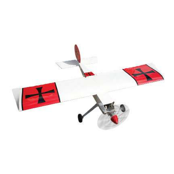
Speciications:
Wingspan---------------70.9 in (180 cm).
Wing area---------------1033.2 sq.in (66.7 sq.dm).
Weight-------------------7.7 lbs (3.5 kg).
Length-------------------57.8 in (146.8 cm).
Engine-------------------10cc - 15cc gasoline
----------------------------.60 -.91 glow engine
----------------------------1200-1500 Watt Brushless Motor
Radio---------------------4 channels with 5 servos.
Electric conversion: Optional.
1
Advertisement
Table of Contents

Related Manuals for Seagull Models CLASSIC UGLY STICK 10-15cc


Summary of Contents for Seagull Models CLASSIC UGLY STICK 10-15cc
- Page 1 A S S E M B L Y M A N U A L “ Graphics and speciications may change without notice “ . Code : SEA255 Speciications: Wingspan---------------70.9 in (180 cm). Wing area---------------1033.2 sq.in (66.7 sq.dm). Weight-------------------7.7 lbs (3.5 kg). Length-------------------57.8 in (146.8 cm).
-
Page 2: Kit Contents
CLASSIC UGLY STICK Instruction Manual. INTRODUCTION. hank you for choosing the CLASSIC UGLY STICK ARTF by SG MODELS. he CLASSIC UGLY STICK was designed with the intermediate/advanced sport lyer in mind. It is a sport air- plane which is easy to ly and quick to assemble. he airframe is conventionally built using balsa, plywood to make it stronger than the average ARTF, yet the design allows the aeroplane to be kept light. -
Page 3: Hinging The Aileron
HINGING THE AILERON. KIT CONTENTS. Note : he control surfaces, including the ai- SEA255 CLASSIC UGLY STICK lerons, elevators, and rudder, are prehinged SEA25501 Fuselage with hinges installed, but the hinges are not SEA25502 Wing set glued in place. It is imperative that you prop- SEA25503 Tail set erly adhere the hinges in place per the steps SEA25504 Aluminum tube... - Page 4 CLASSIC UGLY STICK Instruction Manual. 4) Delect the aileron and completely satu- 7) Repeat this process with the other wing rate each hinge with thin C/A glue. he ailer- panel, securely hinging the aileron in place. ons front surface should lightly contact the wing during this procedure.
-
Page 5: Wing Assembly
WING ASSEMBLY. Please see below pictures. INSTALLING THE AILERON SERVOS. Epoxy. Attach the aluminum tube into wing. Servos Small weight Thread 1) Install the rubber grommets and brass collets onto the aileron servo. Test it the servo into the aileron servo mount. Because the size of servos difer, you may need to adjust the size of the precut openingin the mount. - Page 6 CLASSIC UGLY STICK Instruction Manual. 4) Tape the servo lead to the wing to prevent it from falling back into the wing. Plastic tape. 5) Reinstall the servo into the servo mount and secure the servo inplace using the wood screws provided with you radio system.
- Page 7 AILERON PUSHROD HORN Servo arm. INSTALLATION. Please see below pictures. Snap keeper. Nylon Snap keeper. Hex Nut. Fuel tubing. Use a felt tip pen to mark the wire where it crosses the hole. Use a pair of pliers to put a shrp 90-degree bend in the wire at the mark.
- Page 8 CLASSIC UGLY STICK Instruction Manual. THROTTLE SERVO ARM INSTALLATION. Install adjustable servo connector in the servo arm as same as picture below: Adjustable servo connector. Loctite secure. Servo arm. Wing bolt. hrottle servo arm. INSTALLING THE FUSELAGE SERVOS. Because the size of servos difer, you INSTALLING THE RECEIVER SWITCH.
- Page 9 Switch. INSTALLING THE ENGINE SWITCH. Trim and cut. Switch. Vent tube. Fuel pick up INSTALLING THE STOPPER ASSEMBLY. Fuel fill tube. 1) Using a modeling knife, carefully cut of the rear portion of one of the 3 nylon tubes leaving 1/2” protruding from the 3) Carefully bend the second nylon tube up rear of the stopper.
-
Page 10: Fuel Tank Installation
CLASSIC UGLY STICK Instruction Manual. 5) With the stopper assembly in place, the weighted pick-up should rest away from the rear of the tank and move freely inside the tank. he top of the vent tube should rest just below the top of the tank. It should not touch Ignition Module. -
Page 11: Engine Mount Installation
Blow through one of the lines to ensure the fuel lines have not become kinked inside the fuel tank compartment. Air should low through easily. ENGINE MOUNT INSTALLATION. 1) Locate the items necessary to install the engine mount included with your 140mm model. - Page 12 CLASSIC UGLY STICK Instruction Manual. 6) Connect the Z-bend in the 450mm throttle pushrod to the outer hole of the carburetor arm. 7) Slide the throttle pushrod wire into the tube. Position the engine between the mounts. Use four M4x30mm machine screws to secure the engine to the mount as shown.
- Page 13 ELECTRIC POWER CONVERSION. 1) Locate the items neccessary to install the electric power conversion included with your model. 4mm. 4mm. - Motor : .60 - Propeller: 14x 8 ~ 16x10 - ESC: 60A - 5S-7S Lipo 2) Attach the electric motor box to the irewall suitable with the cross lines drawn on the electric motor box and ire- Blind nut.
-
Page 14: Installing The Spinner
CLASSIC UGLY STICK Instruction Manual. Speed control. Tie wraps. 3x15mm. Battery. INSTALLING THE SPINNER. -
Page 15: Installing The Main Landing Gear
he propeller should not touch any part of the spinner cone. If it does, use a sharp modeling knife and carefully trim away the spinner cone where the propel- ler comes in contact with it. Collar. INSTALLING THE MAIN LANDING GEAR. NOTE : You must now decide if you will assemble the Classic Ugly Stick with tri- cycle landing gear or as a tail dragger. -
Page 16: Nose Gear Installation
CLASSIC UGLY STICK Instruction Manual. NOSE GEAR INSTALLATION. Please see below pictures Collar. M4x20mm. Collar. M4x20mm. -
Page 17: Hinging The Elevators
HINGING THE ELEVATORS. Glue the elevator hinges in place using the same techniques used to hinge the ai- lerons. Steering arm. HORIZONTAL STABILIZER. 1) Using a ruler and a pen, locate the center- line of the horizontal stabilizer, at the trail- ing edge, and place a mark. - Page 18 CLASSIC UGLY STICK Instruction Manual. 4) With the stabilizer held irmly in place, use a pen and draw lines onto the stabilizer Knife. where it and the fuselage sides meet. Pen. 7) When you are sure that everything is aligned correctly, mix up a generous amount of 30 Minute Epoxy.
-
Page 19: Vertical Stabilizer Installation
3) Remove the stabilizer. Using a modeling knife, remove the covering from below the lines you drew. VERTICAL STABILIZER Knife. INSTALLATION. 1) Slide the vertical stabilizer into the slot in the top of the fuselage. he rear edge of the stabilizer should be lush with the rear edge of the fuselage and the lower rudder hinge should engage the precut hinge slot in the... - Page 20 CLASSIC UGLY STICK Instruction Manual. 5) When you are sure that everything is aligned correctly, mix up a generous amount of 30 Minute Epoxy. Apply a thin layer to the mounting slot in the top of the fuselage and to the sides and bottom of the vertical sta- bilizer mounting area.
- Page 21 3) Hold the rudder in place and mark it ELEVATOR - RUDDER PUSHROD where the music wire will enter. When HORN INSTALLATION. you are happy with the it, ill the hole with epoxy and use CA to glue in the 1) Locate items necessary to install eleva- rudder hinges.
- Page 22 CLASSIC UGLY STICK Instruction Manual. Rudder pushrod. M2 clevis. Hex nut. Fuel tubing. Elevator pushrod. INSTALLING BATTERY - RECEIVER. 1) Plug the ive servo leads and the switch lead into the receiver. Plug the battery pack lead into the switch also. 2) Wrap the receiver and battery pack in the protective foam rubber to protect them from vibration.
-
Page 23: Control Throws
2) Mount the wing to the fuselage. Using a couple of pieces of masking tape, place 100 mm them on the bottom of the wing 100mm back from the leading edge of the wing at the wing root. 3) With the model upright, place your ingers on the masking tape and carefully lit the plane. - Page 24 CLASSIC UGLY STICK Instruction Manual.
-
Page 25: Flight Preparation
FLIGHT PREPARATION. PREFLIGHT CHECK. Check the operation and direction 1) Completely charge your trans- of the elevator, rudder, ailerons and mitter and receiver batteries before throttle. your irst day of lying. A) Plug in your radio system per the 2) Check every bolt and every glue manufacturer’s instructions and turn joint in the CLASSIC UGLY STICK everything on. - Page 26 CLASSIC UGLY STICK Instruction Manual. If you have any queries, or are interested in our products, please feel free to contact us Factory : 12/101A - Hamlet 4 - Le Van Khuong Street - Dong hanh Ward - Hoc Mon District - Ho Chi Minh City - Viet Nam. Oice : 62/8 Ngo Tat To Street - Ward 19 - Binh hanh District - Ho Chi Minh City - Viet Nam Phone : 848 - 37114542 or 848- 36018777...
Need help?
Do you have a question about the CLASSIC UGLY STICK 10-15cc and is the answer not in the manual?
Questions and answers