Omron CQM1H series Operation Manual
Hide thumbs
Also See for CQM1H series:
- Operation manual (312 pages) ,
- Operation manual (285 pages) ,
- Replacement manual (54 pages)

Related Manuals for Omron CQM1H series


Summary of Contents for Omron CQM1H series
- Page 1 C at . N o. W 238 - - E 1 - - 8 SYSMAC CQM1H/CQM1-series Dedicated I/O Units OPERATION MANUAL...
- Page 3 CQM1H/CQM1Series Dedicated I/O Units Operation Manual Revised August 2000...
- Page 5 OMRON. No patent liability is assumed with respect to the use of the information contained herein. Moreover, because OMRON is constantly striving to improve its high-quality products, the information contained in this manual is subject to change without notice.
-
Page 7: Table Of Contents
TABLE OF CONTENTS PRECAUTIONS ....... . . 1 Intended Audience . - Page 8 TABLE OF CONTENTS Appendices B Specifications ............. . C Troubleshooting .
- Page 9 TABLE OF CONTENTS PART V ........Analog Output Unit and Analog Power Supply Units .
- Page 10 TABLE OF CONTENTS Appendices I Specifications ............. . PART VII .
- Page 11 TABLE OF CONTENTS Appendices J Specifications ............. . K Block Diagram .
-
Page 13: About This Manual
About this Manual: This manual describes the installation and operation of the CQM1H/CQM1-series Dedicated I/O Units and includes the parts and sections described below. The CQM1H/CQM1-series Dedicated I/O Units consist of the Units listed below. Please read this manual carefully and be sure you understand the information provided before attempting to install and operate the CQM1H/CQM1-series Dedicated I/O Units. - Page 14 Part VI: Sensor Unit Section 1 provides the features and system configuration relating to the Sensor Unit and dedicated sen- sor modules. Section 2 provides the nomenclature and switch settings for the CQM1-SEN01, CQM1-TU001, E3X- MA11, E3C-MA11, and E2C-MA11. Section 3 describes the connections between the CQM1-SEN01 and E3X-MA11, E3C-MA11, E2C- MA11, and CQM1-TU001.
-
Page 15: Precautions
PRECAUTIONS This section provides general precautions for using the Programmable Controller (PC) and related devices. The information contained in this section is important for the safe and reliable application of the Programmable Con- troller. You must read this section and understand the information contained before attempting to set up or operate a PC system. -
Page 16: Intended Audience
It is extremely important that a PC and all PC Units be used for the specified purpose and under the specified conditions, especially in applications that can directly or indirectly affect human life. You must consult with your OMRON representative before applying a PC System to the above-mentioned applications. -
Page 17: Operating Environment Precautions
Application Precautions such problems, external safety measures must be provided to ensure safety in the system. • When the 24-VDC output (service power supply to the PC) is overloaded or short-circuited, the voltage may drop and result in the outputs being turned OFF. -
Page 18: Application Precautions
Application Precautions Application Precautions Observe the following precautions when using the PC System. WARNING Always heed these precautions. Failure to abide by the following precautions could lead to serious or possibly fatal injury. • Always ground to 100 Ω or less when installing the Units. Improper grounding may result in electric shock. - Page 19 Application Precautions • Check that the DIP switches and data memory (DM) are properly set before starting operation. • Check the user program for proper execution before actually running it on the Unit. Not checking the program may result in an unexpected operation. •...
- Page 20 Application Precautions • Set the operating settings of the Temperature Controller properly according to the system to be controlled. • Allow at least 30 minutes after turning ON the Temperature Controller as war- mup time. • Do not use thinner to clean the product. Use commercially available cleaning alcohol.
-
Page 21: Part I
PART I B7A Interface Unit CQM1-B7A02 CQM1-B7A03 CQM1-B7A12 CQM1-B7A13 CQM1-B7A21... -
Page 23: Features And System Configuration
SECTION 1 Features and System Configuration This section describes the general features, system configuration, and word allocation of the CQM1-B7Ajj Interface Units. Features ..............System Configuration . -
Page 24: Features
Section 1-1 Features Features • The CQM1-B7Ajj Interface Unit incorporates the B7A transmission opera- tions for the CQM1H/CQM1 I/O Unit. • The following five models of CQM1H/CQM1 B7A Interface Unit are available. Model No. of points Input Output CQM1-B7A21 CQM1-B7A13 CQM1-B7A03 CQM1-B7A12 CQM1-B7A02... -
Page 25: System Configuration
Connecting Devices Section 1-3 System Configuration The following is a CQM1H/CQM1 system configuration with a B7A Interface Unit. B7A Interface Unit CQM1H/CQM1 Transmission distance: 500 m max. B7A Link Terminal (for input) B7A Link Terminal (for output) Switch Sensor Lamps Note The maximum transmission distance depends on the transmission delay time and the power supply wiring. -
Page 26: Word Allocation
Word Allocation Section 1-4 Output Name Model Transmission delay time Screw terminal model STANDARD (19.2 ms) B7A-R6jj1 B7AS-R6jj1 B7A-R6jj6 RAPID (3 ms) B7AS-R6jj6 Module model B7A-R6A52 STANDARD (19.2 ms) B7A-R6A57 RAPID (3 ms) PC connector models B7A-RjAj3 STANDARD (19.2 ms) B7A-RjAj8 RAPID (3 ms) Note Combine B7A Interface Units and B7A Link Terminals with equal transmission... -
Page 27: Bit Allocation
Bit Allocation Section 1-5 Words from 000 including the input bits incorporated by the CPU are allocated for input and words from 100 are allocated for output as shown in the following illustration. Refer to the CQM1H or CQM1 Operation Manual for details on I/O word allocation. - Page 28 Bit Allocation Section 1-5 CQM1-B7A03 Word no. Termi- 15 to 12 11 to 8 7 to 4 3 to 0 Output Output bits (see note 3) Output m + 1 Output bits (see note 3) CQM1-B7A12 Word no. Termi- 14 to 12 11 to 8 7 to 4 3 to 0...
-
Page 29: Nomenclature And Settings
SECTION 2 Nomenclature and Settings This section provides the nomenclature and switch settings for the CQM1-B7Ajj Interface Units. Nomenclature ............Switch Settings . -
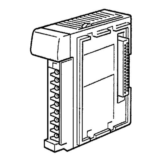
Page 30: Nomenclature
Section 2-1 Nomenclature Nomenclature CQM1-B7A21 Front View Indicators (see following table) B7A Link Terminal connection terminals 1 For connection of a 16-point output B7A Link Terminal. B7A Link Terminal connection terminals 2 For connection of a 16-point Input B7A Link Terminal. External power terminals Required for transmission with the B7A Link Terminal. - Page 31 Section 2-1 Nomenclature CQM1-B7A13 Front View Indicators (see following table) B7A Link Terminal connection terminals 1 For connection of a 16-point Input B7A Link Terminal. Inputs least-significant word (n) data. B7A Link Terminal connection terminals 2 For connection of a 16-point Input B7A Link Terminal. Inputs most-significant word (n+1) data.
- Page 32 Section 2-1 Nomenclature CQM1-B7A03 Front View Indicators (see following table) B7A Link Terminal connection terminals 1 For connection of a 16-point output B7A Link Terminal. outputs least-significant word (m) data. B7A Link Terminal connection terminals 2 For connection of a 16-point output B7A Link Terminal. outputs most-significant word (m+1) data.
- Page 33 Section 2-1 Nomenclature CQM1-B7A12 Front View Indicators (see following table) B7A Link Terminal connection terminals 1 For connection of a 16-point Input B7A Link Terminal. External power terminals Required for transmission with the B7A Link Terminal. Con- nect a 12- to-24 VDC power supply. Terminal screws: M3 (Optimum tightening torque: 0.5 N S m) Indicators...
- Page 34 Section 2-1 Nomenclature CQM1-B7A02 Front View Indicators (see following table) B7A Link Terminal connection terminals 1 For connection of a 16-point output B7A Link Terminal. External power terminals Required for transmission with the B7A Link Terminal. Con- nect a 12- to 24-VDC power supply. Terminal screws: M3 (Optimum tightening torque: 0.5 N S m) Name...
-
Page 35: Switch Settings
Switch Settings Section 2-2 Switch Settings Remove the terminal block to expose the DIP switch underneath. Refer to the CQM1H Operation Manual (W363) or the CQM1 Operation Manual (W226) for the method of removing the terminal block. Use a thin-tipped object, such as a small screwdriver, to set the pins. DIP switch CQM1-B7A21/CQM1-B7A12 Pin no. - Page 36 Switch Settings Section 2-2 Transmission Delay Time Sets the transmission delay time for the B7A Interface Unit. Setting Setting Transmission Delay Time RAPID (3 ms) STANDARD (19.2 ms) (factory setting) Set the transmission delay time to RAPID to enable transmission with high- speed B7A Link Terminals with a transmission delay time of 3 ms.
-
Page 37: Connections
SECTION 3 Connections This section describes the connections between the CQM1-B7Ajj Interface Units and B7A Link Terminals. Connections to B7A Link Terminals ......... . 3-1-1 Recommended Cables . -
Page 38: Connections To B7A Link Terminals
Section 3-1 Connections to B7A Link Terminals Connections to B7A Link Terminals 3-1-1 Recommended Cables The B7A Interface Unit can be connected to the input and output B7A Link Termi- nals using the following cables. Standard Transmission Delay-time Type Cabtire Cable Use a VCTF 0.75 x 3 C cabtire cable (100 m max.) if a power supply is shared and a VCTF 0.75 x 2 C cabtire cable (500 m max.) if power is supplied indepen- dently. - Page 39 Section 3-1 Connections to B7A Link Terminals CQM1-B7A03 Connect to the SIG terminal of the output B7A Link terminal. Word m Connect to the negative power supply ter- minal of the output B7A Link Terminal. Unused Connect to the SIG terminal of the output B7A Link Terminal.
-
Page 40: Wiring
Wiring Section 3-2 Wiring Wiring between the B7A Interface Unit, input B7A Link Terminal, and output B7A Link Terminal sharing a single power supply differs from wiring between Units using independent power supplies as shown in the following diagrams. Standard Transmission Delay-time Link Terminal Single Power Supply Terminal screws: M3.5 B7A Interface Unit... - Page 41 Wiring Section 3-2 Rapid Transmission Delay-time Link Terminal Single Power Supply Terminal screws: M3.5 B7A Interface Unit Terminal screws: M3 B7A Link Terminal Transmission distance: 50 m max. – Shielded cable: 0.75 mm min. – Ground B7A Link Terminal Transmission cable: shielded, 0.75 mm min.
-
Page 43: A Specifications
Appendix A Specifications Standard Specifications The standard specifications of the B7A Interface Unit conform to those of the CQM1H/CQM1 PC. Performance Specifications Item Specification I/O points B7A21: 16 input points (see note 1), 16 output points B7A13: 32 input points (see note 2) B7A03: 32 output points B7A12: 16 input points (see note 1) B7A02: 16 output points... - Page 44 Appendix A Specifications Dimensions These dimensions are the same for all B7A Interface Unit models. (Unit: mm)
-
Page 45: Part Ii
PART II G730 Interface Unit CQM1-G7M21 CQM1-G7N01 CQM1-G7N11... -
Page 47: Features And System Configuration
SECTION 1 Features and System Configuration This section describes the general features, system configuration, and word allocation of the G730 Interface Units. Features ..............System Configuration . -
Page 48: Features
Section 1-1 Features Features The CPU handles the Interface Units as I/O Units, thereby eliminating tedious procedures. Using a G730 Interface Unit allows signals for remote I/O equip- ment, such as switches and lamps, to be handled and controlled by the G730 Remote Terminal. -
Page 49: System Configuration
System Configuration Section 1-2 System Configuration The following are CQM1H/CQM1 system configuration examples with G730 In- terface Units. Configuration with One Master Master (32 input points/32 output points max.) CQM1H/CQM1 RS-485, 200 m max. G730-VI (input model) G730-VO (output model) G730-RI (input model) G730-RO (output model) Switch... - Page 50 System Configuration Section 1-2 Configuration as a Single System with Expansion Masters Master (32 input points/32 output points max.) Expansion Master Unit 1 (max. 32 input points or 32 output points) Expansion Master Unit 2 (max. 32 input points or 32 output points) CQM1H/CQM1 RS-485, 200 m max.
- Page 51 System Configuration Section 1-2 Configuration as Multiple Systems Master, System 1 (32 input points/32 output points max.) Expansion Master Unit 1 (max. 32 input points or 32 output points) Expansion Master Unit 2 (max. 32 input points or 32 output points) Master, System 2 (32 input points/32 output points max.) Expansion Master Unit 1 (max.
-
Page 52: Connecting Devices
Connecting Devices Section 1-3 Connecting Devices 1-3-1 CPU The G730 Interface Unit connects to the following CPUs. Name Model Max. I/O Points (see note) CQM1H-series CQM1H-CPU11 256 (16 words) CQM1H-CPU21 512 (32 words) CQM1H-CPU51 CQM1H-CPU61 CQM1-series CQM1-CPU11-E 128 (8 words) CQM1-CPU21-E CQM1-CPU41-EV1 256 (16 words) -
Page 53: Nomenclature And Settings
SECTION 2 Nomenclature and Settings This section provides the nomenclature and switch settings for the G730 Interface Units. Nomenclature ............Switch Settings . -
Page 54: Nomenclature
Section 2-1 Nomenclature Nomenclature CQM1-G7M21 Master Front View Indicators (see following table) Transmission terminal (Refer to 3-1 Transmission Cables) – Transmission Ready terminals For connection of transmission (Refer to 3-2 External Output cable to Expansion Master or Connection Cables) Slave. Terminals shorted while in trans- mission status with power on. - Page 55 Section 2-1 Nomenclature Note ALM Output: The Slave address and bit address cannot be checked after a failure occurs. It is not possible to differentiate between Open and Short modes. For more information about the G730 Remote Terminal, refer to the G730 I/O Terminal Catalog (J92).
-
Page 56: Switch Settings
Switch Settings Section 2-2 CQM1-G7M01 Output Master Front View Indicators (see following table) Transmission terminal 1 (see page 40) – For connection of transmission cable from Master or Expansion Master. Transmission terminal 2 (see page 40) – For connection of transmission cable to next Expansion Master or Slave. - Page 57 Switch Settings Section 2-2 CQM1-G7M21 Master All pins are factory-set to OFF → OFF↔ON Pin 4 Not used (set to OFF). Pin 3 HOLD/HOLD OFF Setting: Sets the HOLD/HOLD OFF function. This setting determines whether the signal input status to the CPU is held when a transmission error occurs (HOLD) or whether all input bits are cleared (HOLD OFF).
- Page 58 Switch Settings Section 2-2 Pin 2 Expansion Master Unit # Setting: Sets the Expansion Master Unit Number Setting Description Expansion Master is Unit 2 Expansion Master is Unit 1 Pin 1 Input Word Setting: Sets the number of input words (points) occupied at the Expansion Master. Setting Description One word (16 points) of inputs.
-
Page 59: Connections
SECTION 3 Connections This section describes the connections between the G730 Interface Units and G730 Remote Terminals. Transmission Cables ............External Output Connection Cables . -
Page 60: Transmission Cables
Section 3-1 Transmission Cables Transmission Cables Connect wiring in series from the Master, with positive terminals connected to- gether and negative terminals connected together. Set the last connected Slave as the terminator. Do not set an intermediate Slave as a terminator. Total cable length per system: 200 m max. -
Page 61: External Output Connection Cables
External Output Connection Cables Section 3-2 Locate transmission cables away from power cables and high-voltage cables to eliminate the effects of noise. G730 Interface Unit G730 Interface Unit Ex- G730 Interface Unit Ex- Master pansion Master pansion Master – – –... -
Page 63: Operation
SECTION 4 Operation This section provides the operational procedures for the G730 Interface Unit. Word Allocation ............4-1-1 CQM1H/CQM1 Word Allocation . -
Page 64: Word Allocation
Section 4-1 Word Allocation Word Allocation 4-1-1 CQM1H/CQM1 Word Allocation Number of I/O Words The number of I/O words for the G730 Interface Unit Master and Expansion Master can be switched between 1 word and 2 words using the DIP switch. The number of I/O words set affects the word allocations and number of connected Slaves. - Page 65 Section 4-1 Word Allocation The Slave address for Unit 2 can only be used for an 8-point or 16-point Slave. It cannot be used for a 4-point Slave. Master (G7M21) Expansion Master (G7N01) Expansion Master (G7N11) Number inputs: 2 words Set as Unit 1 Set as Unit 2 Number of outputs: 2 words...
- Page 66 Section 4-1 Word Allocation Connect the transmission cables in series from the Master, regardless of the Unit number settings. CQM1H/CQM1 I/O Input Input points points Unit Input word Output word Expansion Masters Mounted Left of the Master Take care of the allocation of Master, Expansion Master Unit 1 and Unit 2 word addresses.
- Page 67 Section 4-1 Word Allocation Additional Unit Mounted Between Master and Expansion Master or Be- tween Two Expansion Masters Take care of the allocation of Expansion Master word addresses. CQM1H/CQM1 I/O Output Input points points points Unit Input word Output word Master of Another System is Mounted Between the Master and Expansion Master or Between Two Expansion Masters of a System Take care that the transmission cables of System 1 and System 2 are not wired...
- Page 68 Section 4-1 Word Allocation Relationship Between The Slave addresses corresponding (i.e. controlled by) each Master/Expansion Master/Expansion Masters Master are shown in the table below. and Slave Addresses The Slave addresses corresponding to each Master and Expansion Master Unit number are fixed. 4-point Slave 8-point Slave 16-point Slave...
- Page 69 Section 4-1 Word Allocation 4-1-4 Word Allocation Example In this example, the Master and output Expansion Master Unit 1 are set to 2 words and the Slaves comprise five 16-point Units and two 4-point Units. The Slave I/O bit addresses corresponding to Unit I/O words and Slave address al- locations are shown in the table below.
-
Page 70: Handling Power On
Transmission Delay Time Section 4-3 Handling Power On After the power is turned on, the Master takes several seconds to recognize all the Slaves. To start operation immediately at power on, write a program for CQM1H/CQM1 to read the Transmission Ready signal and to wait until the Transmission Ready signal turns ON. - Page 71 Transmission Delay Time Section 4-3 For the system shown in the word allocation example on page 49, the time (Tmax) between the input type Slave input signal turning ON, being read by the Slave, and then being read by CQM1H/CQM1 from the Master is calculated as follows (assuming the Slave input ON delay time is 1.5 ms.).
-
Page 73: B Specifications
Appendix A Specifications Standard Specifications The standard specifications of the G730 Interface Units conform to those of the CQM1H/CQM1 PC. Communications Performance Specifications Item Specification Communications method Two-wire, semi-duplex Synchronization method Start-stop Transmission path 2-core cable (VCTF 0.75 X 2 C is recommended) Interface RS-485... - Page 74 Appendix A Specifications Dimensions Common for Master and Expansion Master. Unit: mm...
-
Page 75: C Troubleshooting
Appendix B Troubleshooting Indicator Status During Normal Operation f: Lit, Y: Flashing, X: Not lit Master Expansion Slave Comments Master NODE All T/R indicators flash. Any other indicator display indicates an error. Refer to the table below. Indicator Alarm Table The table below shows the description and remedy of an error occurring in the G730 Interface Unit. -
Page 76: System Error
Appendix B Troubleshooting Error Master Expansion Description Remedy Master NODE Errors –– Input/output type of Match input/output type of before Master/Expansion Master Master/Expansion Master to normal differs from input/output type of input/output type of the operation the corresponding Slave. corresponding Slave. Expansion Masters exist with Expansion Masters exist with different input/output type but... - Page 77 Appendix B Troubleshooting Errors Master Expansion Master NODE I/O word setting error –– –– –– –– –– –– I/O unit overflow Defective CQM1H/CQM1 unit connection No end cover CQM1H/CQM1 initial check NG Master unit error –– –– –– f**(X) Slave set between #28 and #30. ––...
-
Page 79: Part Iii
PART III I/O Link Unit CQM1-LK501... -
Page 81: Features And System Configuration
SECTION 1 Features and System Configuration This section describes the general features, system configuration, and word allocation of the CQM1-LK501 I/O Link Unit. Features ..............System Configuration . -
Page 82: Features
Connecting Devices Section 1-3 Features • The CQM1-LK501 I/O Link Unit can communicate with other PCs via I/O points connected to the SYSMAC BUS Wired Remote I/O System. • The CPU treats the CQM1-LK501 I/O Link Unit as an I/O Unit with 32 input and 32 output points so that the user can communicate with remote PCs with ease. -
Page 83: Word Allocation
Word Allocation Section 1-4 1-3-2 Remote I/O Master The CQM1-LK501 I/O Link Unit connects to the following SYSMAC BUS Master Units. Model C500-RM201 C2000H C1000H (F) C500 (F) CV2000 CV1000 CV500 CVM1 C200H-RM201 C200H/C200HS C200HX/HG/HE Word Allocation The CQM1-LK501 I/O Link Unit is allocated two output and two input words. Master CQM1H/CQM1 Master’s area... -
Page 84: Master Word Allocation
Word Allocation Section 1-4 1-4-2 Master Word Allocation The Master treats the CQM1-LK501 I/O Link Unit as a SYSMAC BUS Remote I/O Slave Unit. Words are allocated to the SYSMAC BUS area and specified by the Master in the same way as other SYSMAC BUS Remote I/O Slave Units. All words to be used in the SYSMAC BUS area are set using the DIP switch of the CQM1-LK501 I/O Link Unit as shown in the following figure. -
Page 85: Nomenclature And Settings
SECTION 2 Nomenclature and Settings This section provides the nomenclature and switch settings for the CQM1-LK501 I/O Link Unit. Nomenclature ............Switch Settings . -
Page 86: Nomenclature
Switch Settings Section 2-2 Nomenclature Indicators (see table) Transmission terminal 1 (refer to 3-1 SYSMAC BUS Cable Connections.) Transmission terminal 2 (refer to 3-1 SYSMAC BUS Cable Connections.) Operation output terminals Operation output terminals must be short-cir- cuited if transmission is normal when the Master is in operating mode. - Page 87 Switch Settings Section 2-2 Terminator Setting Switch The terminator setting switch of the CQM1-LK501 I/O Link Unit mounted to the CQM1H/CQM1 located at the end of the SYSMAC BUS system must be set to Master SYSMAC BUS system Other Slave CQM1H/CQM1 (2) CQM1H/CQM1 (1) terminator...
-
Page 89: Connections
SECTION 3 Connections This section describes the SYSMAC BUS cable connections for the CQM1-LK501 I/O Link Unit. SYSMAC BUS Cable Connections ......... . . -
Page 90: Sysmac Bus Cable Connections
Section 3-1 SYSMAC BUS Cable Connections SYSMAC BUS Cable Connections Connect VCTF 0.75 x 2 C SYSMAC BUS cables to the CQM1-LK501 I/O LInk Unit as shown in the following. Connect the positive signal line from the Master. Connect the negative signal line from the Master. -
Page 91: D Specifications
Appendix A Specifications Standard Specifications The standard specifications of the CQM1-LK501 I/O Link Unit conform to those of the CQM1H/CQM1 PC. SYSMAC BUS Standard Specifications Item Specification Transmission method Time-division multiplex cyclic Communication method Two-wire semi-duplex Transmission path 2-core cable (VCTF 0.75 x 2 C is recommended) Interface RS-485 Transmission speed... -
Page 93: Part Iv
PART IV Analog Input Unit and Analog Power Supply Units CQM1-AD041 CQM1-IPS01 CQM1-IPS02... -
Page 95: Features And System Configuration
SECTION 1 Features and System Configuration This section provides the features and system configuration relating to the Analog Input Unit and Analog Power Supply Units. Features ..............1-1-1 Analog Input Unit . -
Page 96: Features
Section 1-1 Features Features Analog Input Unit Analog Power Supply Unit 1-1-1 Analog Input Unit • The CQM1-AD041 is a SYSMAC CQM1H/CQM1-series Analog Input Unit that converts analog signals into digital signals. • A single Analog Input Unit converts 4-point analog input into 12-bit digital out- put. -
Page 97: System Configuration
Connecting Devices Section 1-3 System Configuration The Analog Input Unit is mounted to the CQM1H/CQM1 CPU as shown in the following illustration. Analog In- put Unit Analog Power Supply Unit Power Supply Unit I/O Unit I/O Unit Sensors • The Analog Input Unit and Analog Power Supply Unit are mounted to the CPU, just like I/O Units. -
Page 98: System Construction
System Construction Section 1-4 System Construction The Analog Input Unit occupies many words and consumes a large current. Therefore when constructing systems incorporating Analog Input Units, the user should take the following into consideration. 1-4-1 Total Number of I/O Words The maximum number of available I/O words for each system varies with the CPU Unit. -
Page 99: Nomenclature And Functions
SECTION 2 Nomenclature and Functions This section provides the nomenclature and functions of the Analog Input Unit and Analog Power Supply Units. Nomenclature ............2-1-1 Analog Input Unit . -
Page 100: Nomenclature
Section 2-1 Nomenclature Nomenclature 2-1-1 Analog Input Unit CQM1-AD041 Front View Left View Indicators Input terminal 1 DIP switch Input terminal 2 Input terminal 3 Input terminal 4 Protective ground terminal Terminal screws: M3 Power supply cable Indicators Name Color Function Green Lit while the CQM1H/CQM1 is turned on and the... - Page 101 Section 2-1 Nomenclature DIP Switch Function The DIP switch is used to decide the operating method of the Analog Input Unit. 3 4 5 6 7 8 9 10 Factory setting The following tables provides DIP switch settings for Analog Input Unit opera- tion.
-
Page 102: Analog Power Supply Unit
Section 2-1 Nomenclature 2-1-2 Analog Power Supply Unit CQM1-IPS01 CQM1-IPS02 Indicators Indicators Connector 1 Connector 2 Connector for the power supply cable of the Analog Input Unit Connectors for the power supply cable of the Analog Input Unit Indicators Name Color Function P/S (incorporated by... -
Page 103: Functions
Functions Section 2-2 Functions 2-2-1 Analog Input Unit Input Range and The Analog Input Unit converts analog data into digital data according to the Conversion Data range set as shown in the following graphs. –10 to 10 V If the Analog Input Unit is set to a range of –10 to 10 V with the DIP switch, data between addresses F830 to 07D0 (hexadecimal) will be converted. - Page 104 Functions Section 2-2 If input data is below the converted range (i.e., the input voltage of the data is less than approximately 0.95 V or the input current of the data is less than approximately 3.8 mA), the broken wire detection function of the Analog Input Unit will be activated.
-
Page 105: Operation
SECTION 3 Operation This section provides the operational procedures for the Analog Input Unit and Analog Power Supply Units. Settings ..............3-1-1 Wiring . -
Page 106: Settings
Section 3-1 Settings Settings 3-1-1 Wiring • Connect a two-conductor twisted-pair shielded cable to the Analog Input Unit. • The input terminals of the Analog Input Unit, to which the two-conductor twisted-pair shielded cable is connected, vary with the input range as shown in the following illustrations. - Page 107 Section 3-1 Settings AC Relay Surge absorber (Okaya Denki’s CR-50500 or equivalent) Solenoid Surge absorber (Okaya Denki’s Solenoid CR-50500 or equivalent) If the Analog Input Unit malfunctions due to external noise through the power line to the Analog Input Unit, insert a noise filter to the power line. The Analog Input Unit may be influenced by noise if the Analog Input Unit and an electric welding machine share a single power source or if the Analog Input Unit is operated near a machine that generates high-frequency electromagnetic waves.
-
Page 108: Bit Number Allocation
Bit Number Allocation Section 3-2 Bit Number Allocation Two input words or four input words can be allocated to the Analog Input Unit, which are specified with the DIP switch of the Analog Input Unit. Refer to page 81, DIP Switch Function for details. 3-2-1 Word Allocation Input words are allocated according to the mounting order (from left to right) of the Units. -
Page 109: Programming And Adjustment
Programming and Adjustment Section 3-3 Programming and Adjustment 3-3-1 Programming This section provides program examples for the Analog Input Unit using four words in the following input ranges. The program examples are not valid for the Analog Input Unit with its mean value processing function activated. Input Input range Word storing conversion data... - Page 110 Programming and Adjustment Section 3-3 The following is an example of SCL instruction use. 00000 SCL(66) DM 0100 DM 0000 * “n” indicates the allocated word for analog input. Set value DM 0100 (BCD) 0000 DM 0101 (Hexadecimal) 0030 DM 0102 (BCD) 0100 DM 0103...
- Page 111 Programming and Adjustment Section 3-3 Scaling is executed so that F830 to 07D0 (hexadecimal) will correspond to 0030 to 0FD0 (hexadecimal). Use the SCL and SCL2 instructions to convert the range further. 00000 ANDW(34) #0FFF DM 0200 XORW(36) #0800 DM 0200 DM 0200 * “n”...
- Page 112 Programming and Adjustment Section 3-3 word that stores the result. DM 0000 to DM 0011 are secured in the example program. ANDW(34) #0FFF Input condition DM 0200 XORW(36) #0800 DM 0200 DM 0200 AVG( ) DM 0200 #0300 DM 0000 * “n”...
- Page 113 Programming and Adjustment Section 3-3 6. Create the following program to scale values in a range between the lower and upper-limit values and designate the lower- and upper-limit values that have been monitored as parameters. Refer to page 89, Scaling for details. 00000 SCL(66) DM 0100...
- Page 114 Programming and Adjustment Section 3-3 4. Put the CQM1H/CQM1 into operation mode or monitor mode and use the peripheral device to monitor the word (DM0200) in which the scaled conver- sion data is stored. The conversion data will be the lower-limit value. 5.
-
Page 115: E Specifications
Appendix A Specifications Standard Specifications The standard specifications of the Analog Input Unit and Analog Power Supply Units conform to those of the CQM1H/CQM1 PC. Performance Specifications CQM1-AD041 Analog Input Unit Item Specification Input signal range Voltage input –10 to 10 V 0 to 10 V 1 to 5 V Current input... - Page 116 Appendix A Specifications Time Lag Required for Data Conversion Analog input Input signal of Analog Input Unit Time Analog input This step-shaped change is Output data of Analog due to the time lag caused Input Unit by the Analog Input Unit’s internal filter circuit.
- Page 117 Appendix A Specifications Dimensions Analog Input Unit 115.7 Analog Power Supply Unit 115.7 Approx. 140...
-
Page 119: F Troubleshooting
Appendix B Troubleshooting Analog Input Unit Kind of error Phenomenon Cause Remedy Indicator The RDY indicator is not lit. 1. The Unit is not connected Refer to the CQM1H/CQM1 properly. Operation Manual and reset the Analog Input Unit. 2. No end cover is attached. The ERR indicator is lit. -
Page 121: Analog Output Unit And Analog Power Supply Units
PART V Analog Output Unit and Analog Power Supply Units CQM1-DA021 CQM1-IPS01 CQM1-IPS02... -
Page 123: Features And System Configuration
SECTION 1 Features and System Configuration This section provides the features and system configuration relating to the Analog Output Unit and Analog Power Supply Units. Features of Analog Output Unit ..........System Configuration . -
Page 124: Features Of Analog Output Unit
System Configuration Section 1-2 Features of Analog Output Unit • The CQM1-DA021 is a SYSMAC CQM1H/CQM1-series Analog Output Unit that converts digital signals into analog signals. • The Analog Output Unit has an output signal current range of 0 to 20 mA and an output signal voltage range of –10 to 10V. - Page 125 System Configuration Section 1-2 CQM1H Operation Manual (W363) or the CQM1 Operation Manual (W226) for details. Unit Current consumption at 5 VDC (mA) CQM1-DA021 90 mA CQM1-IPS01 420 mA CQM1-IPS02 950 mA 1-2-2 CPU The Analog Output Unit occupies two I/O words. Make sure that the total I/O points will not exceed the I/O points of the CPU.
-
Page 127: Nomenclature And Functions
SECTION 2 Nomenclature and Functions This section provides the nomenclature and functions of the Analog Output Unit. Nomenclature ............2-1-1 Functions of Setting Pins . -
Page 128: Nomenclature
Section 2-1 Nomenclature Nomenclature Front View Indicator Output terminal 1 Output terminal 2 DA021 Terminal screws: M3 Power supply cable (Connect to Analog Power Supply Unit) Left Side View Indicator JT1 setting pin JT2 setting pin Power supply cable Indicator The green indicator of the Unit will be lit if the Unit starts normally. -
Page 129: Functions
Functions Section 2-2 Terminals Terminal Usage Output terminal 1 Connect analog output for output 1. Output terminal 2 Connect analog output for output 2. 2-1-1 Functions of Setting Pins The setting pins are used to prohibit negative voltage output. Status Setting pin Left Right... - Page 130 Functions Section 2-2 The following graph shows the voltage output characteristics of the Analog Out- put Unit. Output voltage (V) F800 FC00 0000 0400 07FF Output data (hexadecimal) –5 –10 Note 1. If the setting pins are set to prohibit negative voltage output, no negative voltage will be output.
-
Page 131: Operation
SECTION 3 Operation This section provides the operational procedures for the Analog Output Unit. Settings ..............3-1-1 Cable Connections . -
Page 132: Settings
Section 3-1 Settings Settings 3-1-1 Cable Connections • Connect the power supply cable of the Analog Output Unit to the power supply connector of the Analog Power Supply Unit and secure the power supply cable connector with screws. • The CQM1-IPS02 incorporates two power supply connectors. The power sup- ply cable of the Analog Output Unit can be connected to either one of the power supply connectors. - Page 133 Section 3-1 Settings • Connect a two-conductor twisted-pair shielded cable to the Analog Output Unit. • Do not install power lines or high-tension lines along in close proximity to the Analog Output Unit’s output lines. • The shielded wire must be grounded on the signal reception side. •...
-
Page 134: Bit Number Allocation
Bit Number Allocation Section 3-2 3-1-3 Terminal Arrangement Indicators Input terminal 1 Input terminal 2 Input terminal 3 Input terminal 4 Protective ground terminal Terminal screws: M3 Power supply cable Bit Number Allocation 3-2-1 Word Allocation Output words are allocated according to the mounting order (from left to right) of the Units. -
Page 135: Programming And Adjustment
Programming and Adjustment Section 3-3 3-2-2 Bit Allocation Word Output 1 Output data n + 1 Output 2 Output data Note The shaded parts do not have any influence on the output voltage (current) of the Analog Output Unit. All data is output in binary. Use a program to convert the data from BCD. - Page 136 Programming and Adjustment Section 3-3 If the following DM settings are made, the scaling as shown in the following graph will be performed. (Hexadecimal) → (1) DM 0100 0030 Offset → (2) DM 0101 0100 (BCD) Gain (graph gradient) (Hexadecimal) → (3) DM 0102 0200 (3)/(2)
- Page 137 Programming and Adjustment Section 3-3 If the following DM settings are made, the scaling as shown in the following graph will be performed. In this example, BCD data between 0 to 1000 will be scaled in order to output a current of 4 to 20 mA.
- Page 138 Programming and Adjustment Section 3-3 All data of the following graph is hexadecimal. Output data to the Analog Output Unit 0FFF 0800 FFFF F800 APR instruction 0000 07FF 0800 0FFF execution result data *1: Data 0FFF is equivalent to 07FF as output data. *2: Data 0800 is equivalent to 0000 as output data.
-
Page 139: G Specifications
Appendix A Specifications Standard Specifications The standard specifications of the Analog Output Unit conform to those of the CQM1H/CQM1 PC. Performance Specifications CQM1-DA021 Analog Output Unit Item Specification No. of analog output points Output signal range Voltage output –10 to 10 V Current output 0 to 20 mA External output permissible load... -
Page 141: H Troubleshooting
Appendix B Troubleshooting Analog Output Unit Kind of error Phenomenon Cause Remedy Indicator The RDY indicator is not lit. 1. The Unit is not connected Refer to the CQM1H Operation properly. Manual (W363) or the CQM1 Operation Manual (W226) and 2. -
Page 143: Part Vi
PART VI Sensor Unit CQM1-SEN01 Sensor Unit CQM1-TU001 Remote Console E3X-MA11 Optical Fiber Photoelectric Module E3C-MA11 Photoelectric Module E2C-MA11 Proximity Sensor Module E39-M11 Dummy Module... -
Page 145: Features And System Configuration
SECTION 1 Features and System Configuration This section provides the features and system configuration relating to the Sensor Unit and dedicated sensor modules. Features ..............System Configuration . -
Page 146: Features
Connecting Devices Section 1-3 Features • A maximum of four sensor modules in any combination and order can be mounted to a single CQM1-SEN01. • Sensor modules can be connected to the CQM1-SEN01 via connectors and the CQM1-SEN01 can supply power to the modules, thus greatly saving wiring effort. - Page 147 Connecting Devices Section 1-3 1-3-2 Remote Console Use the mode setting selector of the dedicated CQM1-TU001 Remote Console for the CQM1-SEN01 to set sensor modules mounted to the CQM1-SEN01 to operation monitor mode or teaching mode. 1-3-3 Sensor Modules The following dedicated sensor modules can be mounted to the CQM1-SEN01. Name Model Optical Fiber Photoelectric Module...
-
Page 148: System Construction
System Construction Section 1-4 System Construction The CQM1H/CQM1 treats the CQM1-SEN01 as a four-point Input Unit. Inputs are allocated from word 000 including the built-in input bits of the CPU of the CQM1H/CQM1. The following is an example of word allocation. The CQM1-SEN01 occupies one input word. -
Page 149: Nomenclature And Functions
SECTION 2 Nomenclature and Functions This section provides the nomenclature and switch settings for the CQM1-SEN01, CQM1-TU001, E3X-MA11, E3C-MA11, and E2C-MA11. Nomenclature ............Nomenclature . -
Page 150: Nomenclature
Section 2-1 Nomenclature Nomenclature 2-1-1 Sensor Unit CQM1-SEN01 Output indicators 0, 1, 2, and 3 (orange, lit during operation) Ready indicator Slot (green) Slot Module insertion slots Slot Slot Cover Console connector Indicators Name Color Function Green Lit while the CQM1H/CQM1 is turned ON. 0 to 3 (Output) Orange Lit when the control outputs of sensor modules... - Page 151 Section 2-1 Nomenclature Indicators Name Color Function OPERATION Orange Lit when the control output of the sensor module specified with the module selector is ON. STABILITY Green Lit when the operation of the sensor module specified with the module selector is stable. TEACHING Red/Green Indicates the teaching status of sensitivity setting.
-
Page 152: Optical Fiber Photoelectric Module
Section 2-1 Nomenclature 2-1-3 Optical Fiber Photoelectric Module E3X-MA11 Front View Stability operation indicator (green) Operation indicator Fiber insertion mouth (light emitting termi- (orange) nal) (Refer to 3-4-1 E3X-MA11 Optical Fiber Photoelectric Module for details.) Mode selector (SET for teaching and RUN for normal operation.) (Refer to 2-2 Switch Settings for details.) Fiber insertion mouth (light reception termi- nal) (Refer to 3-4-1 E3X-MA11 Optical Fiber... -
Page 153: Proximity Sensor Module
Section 2-1 Nomenclature Indicators Name Color Function Orange Lit when the control output is ON. STAB Green Lit during stable light ON or dark ON, which can be selected with the operation mode selector. Note When the mode selector is set to SET, the operation indicator and stability op- eration indicator are used to monitor teaching. -
Page 154: Switch Settings
Switch Settings Section 2-2 Note When the mode selector is set to SET, the operation indicator and stability op- eration indicator are used to monitor teaching. Refer to 4-1-1 E3X-MA11 Optical Fiber Photoelectric Module for details. Side View Timer selector Cable length switches 0 ms: No timer... -
Page 155: E2C-Ma11 Proximity Sensor Module
Switch Settings Section 2-2 2-2-2 E2C-MA11 Proximity Sensor Module Cable Length Switches Set the switches as shown below to the length of sensor cable being used either for standard cable lengths or after cutting the cable. Cable length Sensor 0 to 1 m 1 to 2 m 2 to 3 m 3 to 4 m... -
Page 157: Connections
SECTION 3 Connections This section describes the connections between the CQM1-SEN01 and E3X-MA11, E3C-MA11, E2C-MA11, and CQM1-TU001. Wiring Precaution ............3-1-1 E3X-MA11 Optical Fiber Photoelectric Module . -
Page 158: Wiring Precaution
Section 3-1 Wiring Precaution Wiring Precaution 3-1-1 E3X-MA11 Optical Fiber Photoelectric Module Fiber Head The tightening torque applied to the fiber head of each Fiber Unit should be as follows: Screw-mounting Model Column Model Retaining screw (M 3 max.) Spring mounting clip Toothed washers Nuts (attachment) - Page 159 Section 3-1 Wiring Precaution 3-1-3 Connecting Sensors to the E2C-MA11 Do not use excessive force when securing the nut for E2C-X-series sensors. Al- ways use a toothed washer. Model Tightening torque 0.98 N S m E2C-X1A 2.0 N S m E2C-X1R5A Note The above tightening torques assume that a toothed washer is being used.
-
Page 160: Mounting And Dismounting The Sensor Module
Mounting and Dismounting the Sensor Module Section 3-2 Mutual Interference When installing two or more sensors face to face or side by side, ensure that the minimum distances given in the following table are maintained. Sensors can be mounted together in parallel, however, if their cable length switches are set to different values. -
Page 161: Connection Of Cqm1-Tu001 Remote Console
Connection of a Variety of Sensors Section 3-4 Connection of CQM1-TU001 Remote Console • Remove the cover of the Unit and insert the console plug into the console con- nector of the Unit so that the polarity of the console plug and the console con- nector will match. - Page 162 Connection of a Variety of Sensors Section 3-4 Cutting Fiber • Insert a 2.2-mm-dia. fiber into an E39-F4 Fiber Cutter and determine the length of the fiber to be cut. • Press down the Fiber Cutter in a single stroke to cut the fiber. •...
- Page 163 Connection of a Variety of Sensors Section 3-4 Connection • Do not pull or press the Fiber Unit with excessive force. The thin-type optical fiber cable withstands a force of 9.8N maximum and the standard-type optical fiber cable withstands a force of 29.4N maximum. Handle the optical fiber cables with care because they are thin.
- Page 164 Connection of a Variety of Sensors Section 3-4 3-4-2 E3C-MA11 Photoelectric Module Connection Thru-beam model Reflective model Shield Shield Shield White White Shield Note 1. Strip the vinyl insulation off all the connection cords 12 mm from the ends for the receiver and projector terminals and expose each conductor 6 mm from the end of the conductor.
-
Page 165: Sensor Module Operation
SECTION 4 Sensor Module Operation This section provides information on the operation of the CQM1-SEN01. Operation without CQM1-TU001 Remote Console ......4-1-1 E3X-MA11 Optical Fiber Photoelectric Module . -
Page 166: Operation Without Cqm1-Tu001 Remote Console
Section 4-1 Operation without CQM1-TU001 Remote Console Operation without CQM1-TU001 Remote Console When the CQM1-TU001 is connected to the CQM1-SEN01, operations on the CQM1-TU001 precede operations on sensor modules. Operations without con- necting the CQM1-TU001 is explained hereunder. 4-1-1 E3X-MA11 Optical Fiber Photoelectric Module Sensitivity Adjustment There are three sensitivity adjustment methods. -
Page 167: E3C-Ma11 Photoelectric Module
Section 4-1 Operation without CQM1-TU001 Remote Console 4. Move the object and press the teaching button. If teaching is successful, the teaching indicator will turn from orange to green. If teaching is unsuccessful, the teaching indicator (orange) will flash, in which case change the position of the object and the sensing distance that have been set and repeat from step 3. - Page 168 Section 4-1 Operation without CQM1-TU001 Remote Console 3. Set the mode selector to RUN to complete the maximum sensitivity setting of the E3C-MA11. Note The maximum sensitivity of the Sensor Unit can be automatically set regardless of the set distance or light reception. Teaching without a Sensing If any background object exerts an influence when setting the maximum sensi- Object (Only for Diffusive...
-
Page 169: E2C-Ma11 Proximity Sensor Module
Section 4-1 Operation without CQM1-TU001 Remote Console Light Axis Adjustment with If the light projection fiber head axis and the light reception fiber head axis do not Flashing Function agree with each other, and the amount of light received becomes 90% of the peak value or less, the flashing function of the E3C-MA11 will operate. - Page 170 Section 4-1 Operation without CQM1-TU001 Remote Console The ON point will be automatically set at the maximum value of the stable sensing distance. If teaching is unsuccessful, the stability operation indica- tor will flash. In this case make sure that the optical fiber cable of the sensor is connected securely and that there is no sensing object, and then repeat from step 3.
- Page 171 Section 4-1 Operation without CQM1-TU001 Remote Console 4. Move the object to the position where you want the output ON and press the teaching button. If teaching is successful, the teaching indicator will turn from orange to green. 5. Do not move the sensing object and press the teaching button a third time. If teaching is successful, the teaching indicator will turn from green to orange.
-
Page 173: Remote Console Operation
SECTION 5 Remote Console Operation This section provides information on the operation of the CQM1-TU001 Remote Console. Mode Setting ............Sensitivity Adjustment . -
Page 174: Mode Setting
Sensitivity Adjustment Section 5-2 Mode Setting RUN Mode The CQM1-TU001 operates normally with sensors connected in this mode. A sensor module can be selected with the module selector of the CQM1-TU001 in run mode and the operation of the sensor module can be monitored with the op- eration indicator and stability operation indicator of the CQM1-TU001. - Page 175 Sensitivity Adjustment Section 5-2 Teaching with a Sensing Object 1, 2, 3... 1. Place the sensor head in the sensing range of the sensor. 2. Connect the CQM1-TU001 to the CQM1-SEN01. 3. Set the module selector to the number of the sensor module on which teach- ing will be performed, and the set the mode selector of the sensor module to RUN.
- Page 176 Sensitivity Adjustment Section 5-2 Teaching for Position Control 1, 2, 3... 1. Place the sensor head in the sensing range of the sensor. 2. Connect the CQM1-TU001 to the CQM1-SEN01. 3. Set the module selector to the number of the sensor module on which teach- ing will be performed.
-
Page 177: I Specifications
Appendix A Specifications CQM1-SEN01 Sensor Unit Item Specification Input points 4 max. Current consumption 600 mA max. at 5 VDC (supplied from Power Supply Unit). Input response time 8 ms max. Insulation resistance 20 MΩ min. at 500 VDC between FG terminal and all signal terminals. Dielectric strength 1,000 VAC at 50/60 Hz for 1 minute between FG terminal and all signal terminals. - Page 178 Appendix A Specifications E3C-MA11 Photoelectric Module Item Rating Power supply voltage 9 VDC (supplied from Sensor Unit) Current consumption 50 mA max. Response time 1.5 ms max. Timer function 10-ms OFF-delay timer (see note) Indicators Operation indicator (orange) and stability operation indicator (green) Teaching monitor Indicators (operation indicator and stability operation indicator are used)
- Page 179 Appendix A Specifications Dimensions CQM1-SEN01 Sensor Unit 35.4 CQM1-TU001 Remote Console Operation indicator Stability opera- 52.9 16.5 tion indicator Teaching indicator Module selector Mode setting selector Teaching button 3,000 10.2 dia. 12 dia.
- Page 180 Appendix A Specifications E3X-MA11 Optical Fiber Photoelectric Module Stability operation indicator Operation indicator Fiber lock lever 28.1 17.8 26.5 Timer selector Teaching button Operation mode selector Mode setting selector E3C-MA11 Photoelectric Module Operation indicator Four, M2.6 x 6 Stability operation indicator 28.1 17.8 26.5...
- Page 181 Appendix A Specifications Sensor Specifications The following table lists combinations of typical sensors that can be used in combination with each sensor module. E3X-MA11 Sensing Thru-beam model Side view Heat-resistive Screen Item method thru-beam thru-beam thru-beam model model model Feature Long sensing Standard Flexible Long...
- Page 182 Appendix A Specifications Sensing Reflective model Side view Heat-resistive Retroreflecti Item method reflective reflective ve model model model Feature Long Standard Flexible Long Resisting Sensing a sensing sensing cable sensing 150°C transparent distance distance distance object Model E32-D11L E32-DC200 E32-D11 E32-D14L E32-D51 E32-R21 and...
- Page 183 Appendix A Specifications E3C-MA11 Item Thru-beam model Diffuse re- flective Limited reflective model model E3C-S10 E3C-1 E3C-2 E3C-DS5W E3C-DS10 E3C-LS3R 3 ± 0.3 cm Sensing distance 10 cm 5 cm 10 cm Minimum sensing object 2-mm non- 4-mm non- 8-mm non- transparent transparent transparent...
- Page 184 Appendix A Specifications Model Suggested cable Substitute cable Thru-beam model Shielded round cable with A single shielded cable, with vinyl E3C-S10 polyethylene insulation insulation, and conductor with a cross E3C-1 Shield section of 0.3 mm min. E3C-2 Shield White White (polyethylene) (vinyl) Gray (vinyl sheath)
- Page 185 Appendix A Specifications E2C-MA11 The following table gives the characteristics for Sensors combined with the Module. Other E2C-series sensors cannot be connected to the Module. Model Item E2C-CR5B E2C-CR8A E2C-X1A E2C-X1R5A E2C-CR8B E2C-C1A Sensing object Magnetic metal Iron: 5 × 5 × 1 mm Iron: 8 ×...
-
Page 187: Part Vii
PART VII Linear Sensor Interface Units CQM1-LSE01 CQM1-LSE02... -
Page 189: Features And System Configuration
SECTION 1 Features and System Configuration This section provides the features and system configuration relating to the Linear Sensor Interface Unit. Features ..............System Configuration . -
Page 190: Features
System Configuration Section 1-2 Features • When the Linear Sensor Interface Unit is used in a system, linear sensor input signals received by the Unit are converted into appropriate numeric values ac- cording to preset scaling values. • The Linear Sensor Interface Unit compares the scaled conversion data with the four comparison set values (HH, H, L, and LL), ensuring the ease of object discrimination. - Page 191 System Configuration Section 1-2 • The Unit needs zero input and zero reset input for forced zero. • The CQM1-LSE01 does not have monitor output. Word Number The word allocations for a CQM1H/CQM1-series Dedicated I/O Unit are as fol- lows. Input: 001 to 015 Output: 100 to 115...
-
Page 193: Functions
SECTION 2 Functions This section provides an explanation of the scaling, timing hold, data input, teaching, forced zero, and monitor output func- tions. Scaling ..............Timing Hold . -
Page 194: Scaling
Section 2-1 Scaling Scaling The conversion of input voltage or current in a certain range to a value in a cer- tain range is called scaling. For example, if the user converts input voltage or current so to be displayed as a percentage, the converted value will be displayed in the range 0 through 100. -
Page 195: Timing Hold
Timing Hold Section 2-2 Reference When scaling is conducted, the scaled conversion data may exceed the range between 9999 and –9999 even if the input values are within the permissible range. The scaled conversion data that fall outside the permissible measure- ment range are treated as overflow values. - Page 196 Timing Hold Section 2-2 From the moment the reset input is turned ON until the TIMING input is turned ON for the first time after the reset input is turned OFF. Power on Scaled conver- sion data Input TIMING input Reset input Maximum Hold If the timing hold mode is set to maximum hold, the Unit continues data sampling...
- Page 197 Timing Hold Section 2-2 From the moment the reset input is turned ON until the timing input is ON and OFF for the first time after the reset input is turned OFF. Power on Sensing section Scaled conver- sion data Input TIMING input Reset input...
-
Page 198: Scaled Conversion Data/Comparison Result
Teaching Section 2-4 Scaled Conversion Data/Comparison Result Either of the following is stored in the input word. • Scaled conversion data • Result of comparison between the set value and the scaled conversion data Scaled Conversion Data The binary-coded scaled conversion data is stored in the input word allocated to the Unit. -
Page 199: Forced Zero (Zero-Shift)
Forced Zero (Zero-shift) Section 2-5 For example, when setting the X1 value as an input value of the smallest object, execute a scaling command while the smallest object is being sampled. In the same manner, the X2 value can be set as the largest object input value if the scaling command is executed while the largest object is being sampled. -
Page 200: Voltage Monitor Output
Voltage Monitor Output Section 2-6 The nonvolatile memory can store the zero shift value. While the forced-zero state stays in effect, the ZERO indicator is lit. Note The forced zero function is not effective when the timing hold mode is set to peak-to-peak hold. -
Page 201: Nomenclature And Functions
SECTION 3 Nomenclature and Functions This section provides the nomenclature, and terminal and indicator functions of the Linear Sensor Interface Unit. Nomenclature ............Terminals . -
Page 202: Nomenclature
Section 3-1 Nomenclature Nomenclature Front View Indicators Indicators Name Color Function Green Lit when the Linear Sensor Interface Unit is ready for use. Lit when an internal error, such as IC malfunctioning, occurs. BROKEN-WIRE Lit when 1- to 5-V or 4- to 20-mA input to the Unit is disconnected. -
Page 203: Terminals
Terminals Section 3-2 Terminals – – – V INPUT Connect a linear sensor with voltage output to this terminal. The available volt- age ranges of the V INPUT terminal are from –9.999 to 9.999, from –5 to 5, and from 1 to 5 V. I INPUT Connect a linear sensor with a current output range from 4 to 20 mA to this termi- nal. -
Page 205: Connections
SECTION 4 Connections This section describes the connections of the Linear Sensor Interface Unit. Mounting and Wiring ............ -
Page 206: Mounting And Wiring
Section 4-1 Mounting and Wiring Mounting and Wiring Mounting Refer to the CQM1H Operation Manual (W363) or the CQM1 Operation Manual (W226) before mounting this Unit to the PC. Wiring Refer to 3-2 Terminals for the wiring of the terminals. Caution •... -
Page 207: Basic Operation
SECTION 5 Basic Operation This section describes the basic operation of the Linear Sensor Interface Unit using the Programming Console. Operating Method ............Programming Console Operation . -
Page 208: Operating Method
Section 5-1 Operating Method Operating Method Initial parameter Set the operation settings mode. Set the scaling values. Is the Unit in comparison mode? Set the set values. Is the Unit in normal hold mode? Set the hysteresis. Monitoring Initial Parameter Settings Use the Programming Console to write the initial parameters to the output word of the Unit. -
Page 209: Programming Console Operation
Programming Console Operation Section 5-2 Programming Console Operation Refer to the CQM1H Operation Manual (W363) or the CQM1 Operation Manual (W226) for the detailed operating method of the Programming Console. The operation of the Programming Console required for the initial settings is ex- plained below. -
Page 210: Operation Mode
Operation Mode Section 5-3 Operation Mode Settings The operation mode is selected with the operation mode A set command or op- eration mode B set command. The following four items can be selected for the Unit with the operation mode A set command. - Page 211 Operation Mode Section 5-3 Command Each operation mode set command consists of a command code and parame- ter. The following command codes are used for the operation mode A and opera- tion mode B set commands. • Operation Mode A: C000 •...
-
Page 212: Scaling
Scaling Section 5-4 Scaling The setting method of the scaling values is explained below. Refer to 6-1 Scaling Value Teaching for the method to obtain the scaling values from the teaching operation. Settings Scales input values into desired values within a range from –9999 to 9999. X2 – Y2 and X1 –... - Page 213 Scaling Section 5-4 Command The scaling value set command consists of a command code and parameter. The following command codes are used to set the X1, X2, Y1, and Y2 scaling values. • X1 Scaling Value Set: C40j • X2 Scaling Value Set: C41j •...
-
Page 214: Comparison
Comparison Section 5-5 7. When the Unit correctly receives the command, the input word will be set to 2000. c100 c001 WRITE 2000 2000 SHIFT WRITE c100 c001 C420 C420 8. Set 0000 for the Y1 value and 1000 for the Y2 value using the above method. c100 c001 WRITE 0000 0000... - Page 215 Comparison Section 5-5 Command The set value set command consists of a command code and parameter. The following command codes are used for the LL, L, H, and HH set values. • LL Set Value: C70j • L Set Value: C71j •...
-
Page 216: Monitoring
Monitoring Section 5-6 8. Input the hysteresis set command code CA00. The input word will be set to the response CA00. SHIFT SHIFT WRITE c100 c001 CA00 CA00 9. Set 0010 to the output word. 10. When the Unit correctly receives the command, the input word will be set to 0010. - Page 217 Monitoring Section 5-6 Refer to the following table for the ON and OFF conditions of the flags for the comparison results. Scaled conversion data y HH set Scaled conversion data < HH set value value – hysteresis Scaled conversion data y H set Scaled conversion data <...
-
Page 219: Applied Operation
SECTION 6 Applied Operation This section describes the applied operation of the Linear Sensor Interface Unit using the Programming Console. Scaling Value Teaching ........... . Set Value Teaching . -
Page 220: Scaling Value Teaching
Section 6-1 Scaling Value Teaching Scaling Value Teaching The scaling value teach command can be used only when the timing hold in op- eration mode A is set to normal. It is possible to adjust the input scaling values by executing scaling value teach- ing with the scaling value teach command. -
Page 221: Set Value Teaching
Set Value Teaching Section 6-2 5. Set the scaling value teach command code C510 for the X2 value. The input word will be set to the response C510. SHIFT WRITE c100 c001 C510 C510 6. Set 0000 to the output word. When 03E8 is set to the input word, converted from 1000 (i.e., the scaled conversion data of the largest object measured with the Unit), the teaching for the X2 value has been correctly executed. -
Page 222: Forced-Zero Shift
Forced-zero Shift Section 6-3 For the Largest Object 4. Adjust the H value with the largest object next. The input word reads 1000, which is the scaled conversion data of the largest object measured with the Unit, and the output word reads 0000. c100 c001 0000 1000 5. -
Page 223: Bcd Value Read
Monitor Output Section 6-5 BCD Value Read The present scaled conversion data can be read in BCD only when the timing hold in operation mode A is set to normal. Use the present value read command and take the following steps to read the present scaled conversion data in BCD with the Programming Console. - Page 224 Monitor Output Section 6-5 Refer to the following table to set signed binary data to use the monitor output function. Set output binary data Output voltage (V) 2710 (10000) min. 9.999 270F (9999) 9.999 0000 0000 D8F1 (–9999) –9.999 D8F0 (–10000) max. –9.999 There is no setting range restriction except for the following cases.
-
Page 225: Commands
SECTION 7 Commands This section provides details on the commands and responses of the Linear Sensor Interface Unit. Command Usage ............List of Commands . -
Page 226: Command Usage
Section 7-1 Command Usage Command Usage There are four types of commands. The command codes can be set to output word. If no command is used, set 0000 to the output word. When a command is executed, the input word will have a response. If no com- mand is executed, the present scaled conversion data or comparison result will be stored in the input word. - Page 227 Section 7-1 Command Usage Set Commands Operation Mode A Set Operation Mode B Set Scaling Value Set Set Value Set Hysteresis Set Command Command code Parameter Output word Input word Command code Parameter Response 1, 2, 3... 1. Set the command code to the output word. The Unit will check the command code.
-
Page 228: List Of Commands
Commands and Responses Section 7-3 Note The Linear Sensor Interface Unit acknowledges the start or end of a command through a change in the output word value. When “0000” is set to the parameter by the setting command, for example, even if “0000” is set at the end of the com- mand, the command doesn’t end because there is no change in the output word value, not allowing scaled conversion data or comparison result to be set in the input word. -
Page 229: Operation Mode A Read
Commands and Responses Section 7-3 Parameter Monitor output 0: Unchanged 1: Scaled conversion data monitor mode (factory-set) 2: Set data D/A output monitor mode Input type 0: Unchanged 1: ±9.999 V (factory-set) 2: ±5 V 3: 1 to 5 V 4: 4 to 20 mA Timing hold 0: Unchanged... -
Page 230: Operation Mode B Set
Commands and Responses Section 7-3 Response If the correct command code is set to the output word, the command code or pa- rameter is set to the input word as a response. Monitor output 1: Scaled conversion data monitor mode (factory-set) 2: Set data D/A output monitor mode Input type 0: Unchanged... -
Page 231: Operation Mode B Read
Commands and Responses Section 7-3 Parameter Zero shift value storage area 0: Unchanged 1: RAM (factory-set) 2: Nonvolatile memory Number of mean value processings 0: Unchanged 1: 1 2: 2 3: 4 (factory-set) 4: 8 5: 16 Input sampling speed 0: Unchanged 1: Fast 2: Slow (factory-set) -
Page 232: Scaling Value Set
Commands and Responses Section 7-3 Response If the correct command code is set to the output word, the command code or pa- rameter is set to the input word as a response. Zero shift value storage area 1: RAM 2: Nonvolatile memory Number of mean value processings 1: 1 2: 2... -
Page 233: Scaling Value Teach
Commands and Responses Section 7-3 7-3-6 Scaling Value Teach This command can be used only when the timing hold in operation mode A is set to normal. This command is used to execute scaling value teaching. When scaling value teaching is executed, the present input value can be used as the X1 or X2 scal- ing value. -
Page 234: Set Value Set
Commands and Responses Section 7-3 If the wrong command code is set to the output word, the following error code will be set to the input word. E000: This error code will be set to the input word if a nonexisting command code is used. -
Page 235: Set Value Read
Commands and Responses Section 7-3 Response If the wrong command code is set to the output word, the following error code will be set to the input word. E000: This error code will be set to the input word if a nonexisting command code is used. -
Page 236: Hysteresis Read
Commands and Responses Section 7-3 Response If the correct command code or parameter is set to the output word, the same command code or parameter will be set to the input word. If the wrong command code or parameter is set to the output word, one of the following error codes will be set to the input word. - Page 237 Commands and Responses Section 7-3 If the wrong command code or parameter is set to the output word, one of the following error codes will be set to the input word. E000: This error code will be set to the input word if a nonexisting command code is used.
-
Page 239: J Specifications
Appendix A Specifications Standard Specifications The standard specifications of the CQM1-LSE01/LSE02 conform to those of SYSMAC CQM1H/CQM1-series PCs. Performance Specifications Item CQM1-LSE01 CQM1-LSE02 Input No. of analog input points Input range Voltage 1 to 5 V, –9.999 to 9.999 V, –5 to 5 V input Current 4 to 20 mA... - Page 240 Appendix A Specifications External Control Input Specifications Item Specification +10% Input voltage 24 VDC –15% Input impedance TIMING/GATE: 2 kΩ Other control output: 2.2 kΩ Input current TIMING/GATE: 9.2 mA TYP. Other control output: 10 mA TYP. (24 VDC) ON voltage TIMING/GATE: 16.3 VDC min.
-
Page 241: Block Diagram
Appendix B Block Diagram Indicator circuit Analog–Digi- Input CQM1H/CQM1 Voltage/Current input tal conversion circuit circuit internal bus interface Micro- circuit computer Control input power supply (24 VDC) Control input circuit Control input Digital-analog output Nonvola- Monitor output circuit tile memory Internal circuit Input and analog–digital Voltage stabi-... -
Page 243: L Data Processing Timing
Appendix C Data Processing Timing Sampling The Unit processes input data in the following two blocks. • A: Input sampling time = Sampling period x No. of mean value processings • B: Operation process and data set to the data input word Data processing Next data processing The Unit has the following two sampling periods. - Page 244 Appendix C Data Processing Timing Example 3 Timing Hold: Maximum hold No. of Mean Value Processings: 2 Input Sampling Speed: Fast B’ B’ Waiting for next Maximum hold processing This value is invalid. timing input Timing input Data Read When a ladder program is used to automatically read the data to be input, the data is sampled in synchronization with timing input.
- Page 245 Appendix C Data Processing Timing Using Reset Input Connect a bit of the output word to the Unit’s reset input terminal. If reset input is ON, the input word will be set to BBBB (i.e., the factory-set setting of the input word). Take the following steps to set the input word to BBBB. 1, 2, 3...
-
Page 247: M Troubleshooting
Appendix D Troubleshooting Internal Error ERR indicator is lit. Word status Possible cause and remedy BEEE CPU error. Turn the power OFF and then ON again, once. If the ERR indicator is still lit, the Unit needs repairs. B010 RAM error (calibration data error). Turn the power OFF and then ON again, once. -
Page 249: Part Viii
PART VIII Temperature Control Units CQM1-TC001 CQM1-TC002 CQM1-TC101 CQM1-TC102 CQM1-TC201 CQM1-TC202 CQM1-TC301 CQM1-TC302 CQM1-TC203 CQM1-TC204 CQM1-TC303 CQM1-TC304... -
Page 251: Temperature Control Unit Model Numbers
SECTION 1 Temperature Control Unit Model Numbers This section lists the Temperature Control Unit model numbers and the basic specifications for each Unit. - Page 252 Temperature Control Units are classified into models according to the number of input loops, the type of output, and other functions, as listed in the following diagram. CQM1-TCjjj Two input loops, basic functions (Word allocations: 2 input and 2 output words) 001: Thermocouple input (K, J), NPN output 002: Thermocouple input (K, J),...
-
Page 253: Cqm1-Tc20J/Tc30J Temperature Control Units
SECTION 2 CQM1-TC20j/TC30j Temperature Control Units This section describes the features and operation of the CQM1-TC20j/TC30j Temperature Control Units. Features and Word Allocations ..........2-1-1 Features . -
Page 254: Features And Word Allocations
Section 2-1 Features and Word Allocations Features and Word Allocations 2-1-1 Features • The PID with advanced feed-forward circuitry (2 degrees of freedom) of the CQM1-TC20j/TC30j assures stable temperature control. The Units can also be set to ON/OFF control. • Temperature Control Units are available for either 4-loop temperature control or 2-loop temperature control, and Units with 2-loop temperature control pro- vide a heater burnout alarm. -
Page 255: Specifications
Specifications Section 2-2 Specifications General Specifications The general specifications of the CQM1-TC20j/TC30j conform to those of the CQM1H/CQM1 Series. Performance Specifications Specification Item Units for thermocouples Units for platinum resistance (CQM1-TC20j) thermometers (CQM1-TC30j) Sensor type (See previous page for K, J, T, L, R, S, B Pt100, JPt100 temperature ranges.) Number of control loops... - Page 256 Specifications Section 2-2 Heater Burnout Alarm (CQM1-TCj03/TCj04) Item Specification Maximum heater current 50 A, single-phase AC ±5 % FS ±1 digit Input current monitoring accuracy Heater burnout alarm 0.1 to 49.9 A (0.1 A unit) (See note 1.) setting Minimum ON time for 200 ms (See note 2.) detection Note...
- Page 257 Specifications Section 2-2 Current Detector (Sold Separately) E54-CT1 5.8 dia. 10.5 3 Two, 3.5 dia. holes 2.36 dia. E54-CT3 12 dia. Two, M3 (depth: 4) Unit: mm...
-
Page 258: Nomenclature
Nomenclature Section 2-3 Nomenclature Front View Ready indicator (green, lit when the Unit is recognized as the Temperature Control Unit) Four-loop Models OUT1 to OUT4 indicators (orange, lit when control output is ON) Two-loop Models OUT1 and OUT2 indicators (orange, lit when control output is ON) HB1 and HB2 indicators (red, lit when a heater burnout has been detected) - Page 259 Nomenclature Section 2-3 Switch Settings Set all switches before mounting the Unit. Factory settings are shown in bold text in the following table. Item Settings Control method Advanced PID Function DIP Switch (SW1) ON/OFF Control operation for loops 1 Normal (cooling control) and 3 Reverse (heating control) Control operation for loops 2...
- Page 260 Nomenclature Section 2-3 Temperature Ranges Units for Thermocouples The setting ranges are shown in the following table. Indication ranges are the setting range ±20°C/°F. (See note 1.) °C °F Code Input type Binary Binary (4-digit Hex) (4-digit Hex) FF38 to FFFF to 0514 F200 to 1300 FED4 to FFFF to 08FC F300 to 2300...
- Page 261 Nomenclature Section 2-3 5. The set points and input shift values will change as follows if the input type is changed: • The set points will be clamped at the upper or lower limit if the setting range is exceeded. •...
-
Page 262: Terminology And Function Descriptions
Terminology and Function Descriptions Section 2-4 Terminology and Function Descriptions Manual Manipulated Variable The manual manipulated variable can be used only as a time-proportional ratio. Control is continued based on the final output level when automatic control (ON/ OFF or advanced PID) is switched to manual operation. This function enables the output to be controlled artificially without using RUN or STOP commands or altering the input status (e.g., for sensor errors). -
Page 263: Wiring
Wiring Section 2-5 Autotuning (AT) PID calculations using the limit cycle method are performed when autotuning is executed. Parameters cannot be written for loops that are currently being auto- tuned. Hunting cycle Calculated Amplitude PID control Set point AT executed for ON/OFF control AT completed (ampli- tude and hunting cycle measurements com-... - Page 264 Wiring Section 2-5 Units for Platinum Resistance Thermometers CQM1-TC301 CQM1-TC302 CQM1-TC303 CQM1-TC304 (4 loops, NPN (4 loops, PNP (2 loops, heater burnout (2 loops, heater burnout outputs) outputs) alarm NPN outputs) alarm PNP outputs) Loop 1 Loop 1 Loop 1 Loop 1 Loop 2 Loop 2...
-
Page 265: Application
Application Section 2-6 Output Circuits TCj01/TCj03 TCj02/TCj04 • The +DC terminals for NPN outputs are internally connected. • The 0V terminals for NPN outputs are internally connected. • Heater burnout alarm outputs (HB1 and HB2) are latched outputs, i.e., they will not reset by themselves. - Page 266 Application Section 2-6 Output word Loop number: 1 to 4 Item To Be Set Item To Be Monitored Value Item to be set Value Item to be monitored Set point Set point Proportional band (for advanced PID) Proportional band (for advanced PID) Integral time (for advanced PID) Integral time (for advanced PID) Derivative time (for advanced PID)
- Page 267 Application Section 2-6 Setting and Indication Ranges for Setting and Monitor Items Decimal values are given in parentheses. Setting/Monitor item Binary indications BCD indications Unit Memory Range Default Range Default °C/°F Set point Depends on 0000 Depends on 0000 Written to RAM input type.
- Page 268 Application Section 2-6 If a power interruption or other problem prevents confirming the write opera- tion, reset the value after power is restored or the problem corrected. Status Data Units with Four Loops Input word Loop number Control output Autotuning Sensor error 0: OFF 0: Normal...
-
Page 269: Using Operation Control Commands
Application Section 2-6 2-6-2 Using Operation Control Commands The following procedure is used to control the Unit. 60 ms max. See note. Output word Cjjj Cjjj Input word 1, 2, 3... 1. Output word: An operation control command (Cjjjj) is set to specify the loop and the operation. - Page 270 Application Section 2-6 3. The following table shows the conditions required to execute the operation control commands and the error codes that will occur when the command causes an error. Current status STOP Auto Manual Cancel Write I/O allocation Mode Mode commands Cjjj...
-
Page 271: Iotc
IOTC(––) Section 2-7 Executing Commands from a Programming Console The following words are allocated to the Temperature Control Unit in these ex- amples: Input word = IR 001 Output word = IR 100 The following procedure would be used to write a set point of 100 °C for loop 1 I/O Allocation Commands and then monitor the process value for loop 1. -
Page 272: Sending I/O Allocation Commands
IOTC(––) Section 2-7 2-7-1 Sending I/O Allocation Commands IOTC(––) can be used to set, write, or monitor more than one data item at the same time, simplifying the ladder program. IOTC (––) C: First word of I/O command area for Temperature Control Unit S: First source word containing write data D: First destination for read data First word... -
Page 273: Sending Operation Control Commands
IOTC(––) Section 2-7 Operand Data Ranges Area IR or SR 000 to 247 000 to 255 000 to 252 HR 00 to HR 94 HR 00 to HR 99 HR 00 to HR 99 AR 00 to AR 22 AR 00 to AR 27 AR 00 to AR 27 LR 00 to LR 58 LR 00 to LR 63... - Page 274 IOTC(––) Section 2-7 Operation Control Commands Command Operation (Set in output word.) STOP CCCj (j = 1 to 4 or A) CCDj (j = 1 to 4 or A) CDCj (j = 1 to 4 or A) Manual Mode CDDj (j = 1 to 4 or A) Auto Mode CFCj (j = 1 to 4 or A) Autotuning...
- Page 275 IOTC(––) Section 2-7 Word Allocations The following words are allocated to the Temperature Control Unit. Input word: IR 001 Output word: IR 100 (1) Data for Changing the Set Point and Control Period Word Contents Word Setting Word Monitor DM 0000 0100 Process DM 0100...
- Page 276 IOTC(––) Section 2-7 25315 01600 01600 CMP (20) Power ON and Unit initialization completed. #FFFF 25506 (=) Unit reset after initialization. FFFF indicated ASL (25) for binary indications. 01601 IOTC (––) DM 0000 I/O allocation commands sent. (Writing set point and control cycle) DM 0100 DM 0200 25506 (=)
- Page 277 IOTC(––) Section 2-7 Sample Program 2 The IOTC(––) instruction cannot be used with a CQM1H CPU Unit with a lot number earlier than 0160. Switch Settings The following switch settings are used. Function DIP switch (SW1): Pins 1 and 5 turned ON = PID heating control , °C unit, 4-digit BCD Input type DIP switch (SW2): Pins 1 and 5 turned ON = Thermocouples, 0.0 and 500.0 °C, loops 1 to 4 For loop 1: Power supply turned ON (STOP status), set point for set to 100.0 °C,...
- Page 278 IOTC(––) Section 2-7 01602 MOV (21) Set point (100.0 °) written to out- #1000 put word. CMP (20) Set point reception checked. #C071 25506 (=) ASL (25) Set point write confirmed. 00115 00114 00113 00112 01603 Error check (indicated set point 01701 was written correctly).
-
Page 279: Troubleshooting
Troubleshooting Section 2-8 Troubleshooting Error Control output Remedy Watchdog timer error “EEEE” set in input OFF for all outputs. Turn the power supply OFF and then back word. ON. If the error persists, replace the Unit. RAM read/write error “E100” set in input word. -
Page 280: Command Tables
Command Tables Section 2-9 Command Tables I/O Allocation Commands Output word Loop number: 1 to 4 Item To Be Set Item To Be Monitored Value Item to be set Value Item to be monitored Set point Set point Proportional band (for advanced PID) Proportional band (for advanced PID) Integral time (for advanced PID) Integral time (for advanced PID) -
Page 281: Cqm1-Tc00J/Tc10J Temperature Control Units
SECTION 3 CQM1-TC00j/TC10j Temperature Control Units This section describes the features and operation of the CQM1-TC00j/TC10j Temperature Control Units. Features and Word Allocations ..........3-1-1 Features . -
Page 282: Features And Word Allocations
Section 3-1 Features and Word Allocations Features and Word Allocations 3-1-1 Features • The PID with advanced feed-forward circuitry (2 degrees of freedom) of the CQM1-TC00j/TC10j assures stable temperature control. The Units can be set to ON/OFF control. • CQM1-TC00j Temperature Control Units... -
Page 283: Specifications
Specification Section 3-2 Specifications General Specifications The general specifications of the CQM1-TC00j/TC10j conform to those of the CQM1H/CQM1 Series. Performance Specifications Item Specification CQM1-TC00j K: –200 to 1,300 °C (–300 to 2,300 °F) Input sensors and set Sensors used with CQM1-TC00j J: –100 to 850 °C (–100 to 1,500 °F) point ranges thermocouples... -
Page 284: Nomenclature
Nomenclature Section 3-3 Nomenclature Front View Ready indicator (green, lit when the Unit is rec- Word number indicator (orange, lit when two words are ognized as the Temperature Control Unit) used and not lit when a single word is used) Terminal screws: M3 (Optimum tightening torque: 0.5 N Side View... -
Page 285: Control Modes
Nomenclature Section 3-3 3-3-1 Control Modes Control is performed independently for each control loop based on the set point data. The relationship between the set point data and the control operation is shown in the following table. Set point Control operation F999 to 9999 Normal temperature control performed. -
Page 286: Wiring
Wiring Section 3-4 Wiring Wiring CQM1-TC001 CQM1-TC002 – – Loop 1 Loop 1 Cold junction Cold junction – – compensator Loop 2 compensator Loop 2 Loop 1 Loop 1 Loop 2 Loop 2 + DC + 24 VDC + 24 VDC Note When using only one control loop, short-circuit the loop 2 input terminals. -
Page 287: Application Examples
Application Examples Section 3-5 Output Interface Output Characteristics +10% Maximum switching capability 100 mA, 24 VDC –15% Leakage current 0.3 mA max. Residual voltage 3.0 V max. +10% External supply voltage 15 mA min., 24 VDC –15% (excluding load current) Output Circuits CQM1-TCj01 (NPN) CQM1-TCj02 (PNP) -
Page 288: Run/Stop And Error Processing Program
Application Examples Section 3-5 each digit is shown below. CQM1-TC00j: 10 , e.g., F999 = –999 –1 CQM1-TC10j: 10 , e.g., F999 = –99.9 3. The process value data will be set to FFFF during initialization; do not read the data as the process value at this time. DM 0000 Write a value in the following ranges to DM 0000 according to the sensor to be used. - Page 289 Application Examples Section 3-5 Always ON Flag 25313 CMP(20) The contents of IR 001 is compared to FFFF to confirm that the Temperature Control has com- #FFFF pleted initialization processing. 25506 If the process value (contents of IR 001) is not 01600 FFFF, IR 01600 is turned ON to indicate that initialization has been completed.
-
Page 290: On/Off Control
Application Examples Section 3-5 01700 Input sensor error processing program If IR 01700 is ON, check the connections to the input sensor and cold junction compensator. If connections are correct for both the input sen- sor and cold junction compensator, replace the Unit. -
Page 291: Advanced Pid Control
Application Examples Section 3-5 the Temperature Control Unit is adjusted. If the hunting is not within the permissi- ble range determined by the user, use advanced PID control. Temperature Hysteresis Time 100% 3-5-4 Advanced PID Control If advanced PID control (i.e., SW1-1 is turned ON) is selected, the Temperature Control Unit will operate with the P value fixed to 40.0, the I value fixed to 240, and the D value fixed to 40. -
Page 292: At (Expansion Mode)
AT (Expansion Mode) Section 3-6 AT (Expansion Mode) To enter the Expansion Mode, change the connection of jumper connector from 2-3 to 1-2. Left-side View of the Unit MODE Default setting Change the connection to 1-2 MODE Expansion Mode MODE TEST Do not change this connection. -
Page 293: Manual Settings (Expansion Mode)
AT (Expansion Mode) Section 3-6 c100 c001 0100 0098 Write the AT start code “CF00” to the output word of the relevant loop and con- firm that the input word will become CF00. c100 c001 CF00 CF00 Set SP to 100 °C again. c100 c001 0100 0098 To cancel auto-tuning, use the code “CF01”... - Page 294 AT (Expansion Mode) Section 3-6 Write an allocation change code to the output for allocation changes. The follow- ing is the format of the allocation change code. Data number on the input side (select from the following table) Data number on the output side (select from the following table) Output side Input side Enabled...
-
Page 295: Set Value Read
AT (Expansion Mode) Section 3-6 Data Status Word The following are set to “1” under the conditions given. Loop 1: Sensor error Loop 2: Sensor error Not used Loop 1: Auto-tuning (AT) execute Loop 2: Auto-tuning (AT) execute Loop 1: Control output ON Loop 2: Control output ON... -
Page 296: Set Value Write
AT (Expansion Mode) Section 3-6 5. Read the control period. Refer to the above procedure and replace the allocation change code “C010” with “C050” and write it as the control period. 6. Read the input shift. Refer to the above procedure and replace the allocation change code “C010”... -
Page 297: Troubleshooting
Troubleshooting Section 3-7 6. Write the input shift. Refer to the above procedure and replace the allocation change code “C110” with “C660” and write it as the input shift. 7. Return to the original status. Refer to the above procedure and replace the allocation change code “C110”... -
Page 298: Revision History
Revision History A manual revision code appears as a suffix to the catalog number on the front cover of the manual. Cat. No. W238-E1-8 Revision code The following table outlines the changes made to the manual during each revision. Page numbers refer to the previous version. -
Page 299: Revision History
Revision History Revision code Date Revised content September 1999 Information relating to CQM1H added. August 2000 CQM1-TC20j/TC30j were added to part VIII and part VIII was restructured. The following specific changes were also made. Page xvi: Additions made to safety precautions. Pages xvii and xviii: Additions and changes made to application precautions.
Need help?
Do you have a question about the CQM1H series and is the answer not in the manual?
Questions and answers