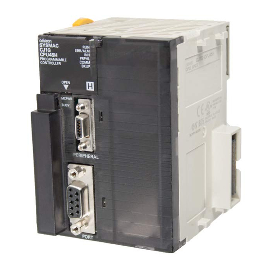
Omron CQM1H Replacement Manual

Omron CQM1H Replacement Manual

Programmable controllers
Hide thumbs Also See for CQM1H:

Advertisement

CQM1H/CJ1M/CJ1G
Programmable Controllers
Replacement Guide
From CQM1H to CJ2M
From CJ1M/CJ1G to CJ2M

Advertisement

Table of Contents
loading

Summary of Contents for Omron CQM1H

  • Page 1 CQM1H/CJ1M/CJ1G Programmable Controllers Replacement Guide From CQM1H to CJ2M From CJ1M/CJ1G to CJ2M...
  • Page 2 About this document This document provides the reference information for replacing CQM1H/CJ1M/CJ1G PLC systems with CJ2M series PLC. This document does not include precautions and reminders; please read and understand the important precautions and reminders described on the manuals of PLCs (both of PLC used in the existing system and PLC you will use to replace the existing PLC) before attempting to start operation.
  • Page 3: Related Manuals

    CS/CJ Series Loop Control Boards/Process-control CPU Units /Loop-control CPU Units OPERATION MANUAL CS/CJ Series Loop Control Boards/Process-control CPU Units /Loop-control CPU Units FUNCTION BLOCK W407 REFERENCE MANUAL W364 CQM1H Series Programmable Controllers Inner Boards PROGRAMMING MANUAL W365 CQM1H-SCB41 SERIAL COMMUNICATIONS BOARD OPERATION MANUAL W238 CQM1H/CQM1 Series Dedicated I/O Units OPERATION MANUAL...
  • Page 4 WHETHER SUCH CLAIM IS BASED ON CONTRACT, WARRANTY, NEGLIGENCE, OR STRICT LIABILITY. In no event shall the responsibility of OMRON for any act exceed the individual price of the product on which liability is asserted. IN NO EVENT SHALL OMRON BE RESPONSIBLE FOR WARRANTY, REPAIR, OR OTHER CLAIMS...
  • Page 5: Dimensions And Weights

    Performance data given in this manual is provided as a guide for the user in determining suitability and does not constitute a warranty. It may represent the result of OMRON's test conditions, and the users must correlate it to actual application requirements. Actual performance is subject to the OMRON Warranty and Limitations of Liability.
  • Page 6: Application Considerations

    Application Considerations SUITABILITY FOR USE OMRON shall not be responsible for conformity with any standards, codes, or regulations that apply to the combination of products in the customer's application or use of the products. At the customer's request, OMRON will provide applicable third party certification documents identifying ratings and limitations of use that apply to the products.
  • Page 7: Table Of Contents

    1. Performance specifications 1.1 CQM1H/CJ2M specifications comparison 1.2 CJ1M/CJ2M specifications comparison 1.3 CJ1G/CJ2M specifications comparison 2. System Configurations 2.1 CQM1H/CJ2M system comfiguration comparison 2.2 CJ1M/CJ1G/CJ2M system comfiguration comparison 3. Memory area 3.1 CQM1H/CJ2M memory area comparison 3.2 CJ1M/CJ1G/CJ2M memory area comparison 4.
  • Page 8: Performance Specifications

    C200H-PRO27 CQM1-PRO01 Note1. One word of CQM1H corresponds to one step of CJ2M. For instance, replacement model of CQM1H-CPU51 (7.2k word) is CJ2M-CPU*2 (10k step), since the program capacity of 7.2k step or larger is required for replacement. Note that the number of steps for an instruction might be different in CQM1H and CJ2M.
  • Page 9: Cj1M/Cj2M Specifications Comparison

    1.2 CJ1M/CJ2M specifications comparison The table below lists the major difference in specifications of the CJ1M series and CJ2M series. Item CJ1M-CPU** CJ2M-CPU** Number of I/O points CPU*1: 160 points 2,560 points CPU*2: 320 points CPU*3: 640 points Program capacity CPU*1: 5k step CPU*1: 5k step CPU*2: 10k step...
  • Page 10: Cj1G/Cj2M Specifications Comparison

    1.3 CJ1G/CJ2M specifications comparison The table below lists the major difference in specifications of the CJ1G and CJ2M series. Item CJ2M-CPU** CJ1G-CPU4*H/CPU4* Number of I/O points CPU42H/43H: 960 points 2,560 points CPU44/45/44H/45H: 1280 points Program capacity CPU42H: 10k step CPU*1: 5k step CPU43H: 20k step CPU*2: 10k step CPU44/44H: 30k step...
  • Page 11: System Configurations

    However, there are some differences in usage, connecting method with external devices, and input/output specifications. Please check if the CJ series unit can be used instead of the CQM1H units, by referring to the user's manuals of both series.
  • Page 12 Unit CQM1H CJ2M Relay output units CQM1-OC221 CJ1W-OC201 Terminal block/250VAC 24VDC 2A/8 points Terminal block/250VAC 24VDC 2A/8points Independent common Independent common CQM1-OC222 CJ1W-OC211 Terminal block/250VAC 24VAC 2A/16 Terminal block/250VAC 24VDC 2A/16 points points CQM1-OC224 CJ1W-OC201 Terminal block/250VAC 24VDC 2A/8 points...
  • Page 13: Cj1M/Cj1G/Cj2M System Comfiguration Comparison

    2.2 CJ1M/CJ1G/CJ2M system comfiguration comparison Same Power Supply Unit, Special I/O Units, and Basic I/O Unit can be used for CJ1M/CJ1G Series and CJ2M Series. ♦Built-in I/O CJ1M CJ2M CJ1G Built-in I/O function Built-in I/O function Built-in CPU funciton will be available by adding the CJ2M-MD211/CJ2M-MD212 not supported Up to two units can be mounted.
  • Page 14: Memory Area

    3. Memory area 3.1 CQM1H/CJ2M memory area comparison The difference of the memory area of the CQM1H series and CJ2M series is shown using an example of CQM1H-CPU61 and CJ2M-CPU**. ♦CIO area CQM1H-CPU61 CJ2M-CPU** IR000 0000 I/O Area Input Area...
  • Page 15 ♦ Area other than CIO Area CQM1H-CPU61 CJ2M-CPU** W000 Work Area W511 HR00 Holding Area H000 Holding Area HR99 H511 AR00 Auxiliary Area A000 Auxiliary Area AR27 A959 A960 Auxiliary Area A1471 Auxiliary Area A10000 A11535 T/C000 Timer/Counter T0000 Timer Completion...
  • Page 16: Cj1M/Cj1G/Cj2M Memory Area Comparison

    3. Memory area 3.2 CJ1M/CJ1G/CJ2M memory area comparison This section explains the difference of the memory area of the CJ1M series, CJ1G series and CJ2M series, using an example of CJ1M-CPU2*, CJ1G-CPU4*H/4* and CJ2M-CPU**. ♦ CI/O area CJ1M-CPU2* CJ1G-CPU4*H/4* CJ2M-CPU** 0000 I/O Area 0000...
  • Page 17 ♦ Area other than CIO Area CJ1M-CPU2* CJ1G-CPU4*H/4* CJ2M-CPU** W000 Internal I/O Area W000 Internal I/O Area W000 Internal I/O Area W511 W511 W511 H000 Holding Area H000 Holding Area H000 Holding Area H511 H511 H511 A000 Auxiliary Area A000 Auxiliary Area A000 Auxiliary Area...
  • Page 18: I/O Area Allocation

    4. I/O Area Allocation This section explains the difference of I/O area allocation in CQM1H, CJ1M/CJ1G Series, and CJ2M series. ♦Unit Area Allocation for CQM1H The I/O words are allocated to I/O Units and Dedicated I/O Units in the order of the unit mounting position from the left to right.
  • Page 19 When I/O Area is used in the ladder program, change the CIO area and bit address using the “Change All” or “Replace” functions of CX-Programmer. Note1: Unit area allocation same as CQM1H can be configured for CJ2M system, by setting the start address for each unit using CX-Programmer V9.1 or later (For some systems, same allocation can not be made).
  • Page 20: Instructions

    5. Instructions The instruction specification is different in CQM1H series and CJ1M/CJ2M series. The Appendix explains the difference in operand and flags. Refer to the Appendix for details. ・A-1 Instruction operations Explains difference in instructions and operand. Least necessary adjustment after program conversion on the CX-Programmer.
  • Page 21 Operand3 First PV word: First word with new PV: (Only when Operand 2=002.) (Only when Operand 2=002.) PLB High-speed counter 1, or 2, High-speed counter input 0 or 1, Linear mode Linear counting mode (increment/decrement pulses) = F8388608 to 08388607 High-speed counter input 2 or 3, Linear mode (increment/decrement pulses) <CJ2M only>...
  • Page 22 ♦ HIGH-SPEED COUNTER PV READ (PRV) CQM1H CJ1M/CJ2M CQM1H CJ1M/CJ2M Operand1 Port specifer: Port specifer: 001= PLB High-speed counter 1 #0010= High-speed counter input 0 002= PLB High-speed counter 2 #0011= High-speed counter input 1 001= PLB Pulse output 1...
  • Page 23 Operand3 First destination word: First destination word: When Operand 2=000 When Operand 2=#0000 PLB High-speed counter 1 or 2, Linear High-speed counter 0 or 1, Linear mode, (Not counting mode: for incremental pulse input) F8388608 to 08388607 High-speed counter 2 or 3, Linear mode, (Not for PLB High-speed counter 1 or 2, Ring incremental pulse input) <CJ2M only>...
  • Page 24 ♦ REGISTER COMPARISON TABLE (CTBL) CQM1H CJ1M/CJ2M CQM1H CJ1M/CJ2M Operand1 Port specifer: Port specifer: 001= PLB High-speed counter 1 #0000= High-speed counter input 0 002= PLB High-speed counter 2 #0001= High-speed counter input 1 #0002= High-speed counter input 2 (CJ2M only)
  • Page 25 <Target value comparison table> Linear mode CQM1H CJ1M/CJ2M (BCD 4 digits) 0001 to 0048 (BIN 4 digits) 0001 to 0030Hex Number of target values Number of target values (BCD 8 digits) F8388608 (BIN 8 digits) 80000000 Target value #1, lower 4 digits...
  • Page 26 <Range comparison table> (Always contains 8 ranges) Linear mode CQM1H CJ1M/CJ2M (BCD 8 digits) F8388608 (BIN8 digits) 80000000 Lower limit #1, lower 4 digits Lower word of range 1 lower limit to 08388607 to 7FFFFFFF Lower limit #1, upper 4 digits...
  • Page 27 ♦ SPEED OUTPUT (SPED) CQM1H CJ1M/CJ2M CQM1H CJ1M/CJ2M Operand1 Port specifer: Port specifer: 001= PLB Pulse output 1 #0000= Pulse output 0 002= PLB Pulse output 2 #0001= Pulse output 1 #0002= Pulse output 2 (CJ2M only) #0003= Pulse output 3 (CJ2M only)
  • Page 28 ♦ SET PULSES (PULS) CQM1H CJ1M/CJ2M CQM1H CJ1M/CJ2M Operand1 Port specifer: Port specifer: 001=PLB Pulse output 1 #0000= Pulse output 0 002=PLB Pulse output 2 #0001= Pulse output 1 #0002= Pulse output 2 (CJ2M only) #0003= Pulse output 3 (CJ2M only)
  • Page 29 ♦ ACCLERATION CONTROL (ACC) CQM1H CJ1M/CJ2M CQM1H CJ1M/CJ2M Operand1 Communications port: Port specifer: 001= PLB Pulse output 1 #0000= Pulse output 0 002= PLB Pulse output 2 #0001= Pulse output 1 #0002= Pulse output 2 (CJ2M only) #0003= Pulse output 3 (CJ2M only)
  • Page 30 CQM1H CJ1M/CJ2M - Mode2 (Deceleration + Independent mode PULS instruction PULS instruction Port specifer Port specifier Control Data Pulse type Relative/Absolute Number of pulses Number of pulses CW/CCW ACC instruction ACC instruction Communications port Port specifier Mode specifier: 002 Mode specifier...
  • Page 31 CQM1H CJ1M/CJ2M Mode0 (Accel + Independent mode) *When acceleration/deceleration rate is same. PULS instruction PULS instruction Port Specifier Port specifier Control data Pulse type Relative/Absolute Number of pulses Number of pulses CW/CCW ACC instruction ACC instruction Port Specifier Port Specifier...
  • Page 32 CQM1H CJ1M/CJ2M Mode1 (Acceleration + Continuous mode)/Mode3 (Deceleration + Continuous mode) PULS instruction Port specifier Control Data Number of pulses CW/CCW ACC instruction ACC instruction Port specifier Port specifier Mode specifier: 001/003 Mode specification D12D11 D08D07 D04D03 Continuous mode Always 0...
  • Page 33 ♦ PULSE OUTPUT (PLS2) CQM1H CJ1M/CJ2M CQM1H CJ1M/CJ2M Operand1 Communications port: Port specifer: 001= PLB Pulse output 1 #0000= Pulse output 0 002= PLB Pulse output 2 #0001= Pulse output 1 #0002= Pulse output 2 (CJ2M only). #0003= Pulse output 3 (CJ2M only)
  • Page 34 CQM1H CJ1M/CJ2M PLS2 instruction PLS2 instruction Communications port Port specifier Direction specifier Mode specifier D12D11 D08D07 D04D03 CW/CCW Direction Mode Always 0Hex Output method 0Hex: CW/CCW output 0Hex: Relative pulse Accel/Deccel rate Acceleration rate S1+1 Target frequency Deceleration rate S1+2...
  • Page 35 ♦ PULSE WITH VARIABLE DUTY FACTOR ( PWM ) CQM1H CJ1M/CJ2M CQM1H CJ1M/CJ2M Operand 1 Communications Port: Port specifier: <CJ1M-CPU22/23: PWM output 0 and 1 only, 001=PLB Pulse Output1 CJ1M-CPU21: PWM output 0 only> 002=PLB Pulse Output 2 #0000= PWM output 0 (Frequency unit of 0.1Hz, Duty factor unit of #0001=PWM output 1(Frequency unit of 0.1Hz, Duty factor unit of...
  • Page 36: I/O Instructions

    5.2 I/O instructions I/O instructions corresponds to the convenient instructions of CQM1H have been added for CJ1M CPU Unit Ver.2.0 or later and CJ2M CPU Unit. A part of specifications of those instructions are different; refer to the table below for details of difference in Operands. The execution time of each instruction is also different; be sure to check the operation for system safery.
  • Page 37 Em/DM area boundary has been exceeded. errors, since they are handled as Illegal (EM can be used with CQM1H-CPU61 only.) access error). - D and D+1 are not in the same data area. - Other than above, ER flag is OFF.
  • Page 38 EM/DM area boundary has been exceeded. errors, since they are handled as Illegal (EM can be used with CQM1H-CPU61 only.) access error). - R and R+1 are not in the same data area. - Other than above, ER flag is OFF.
  • Page 39 ♦ 7-SEGMENT DISPLAY OUTPUT (7SEG) CQM1H CJ1M/CJ2M CQM1H CJ1M/CJ2M Operand1 First source word: Source word: [S1 ]: Rightmost 4 digits [S1 ]D15 to D12: Digit 4 [S1+1]: Leftmost 4 digits D11 to D08: Digit 3 D07 to D04: Digit 2...
  • Page 40 EM/DM area boundary has been exceeded. errors, since they are handled as Illegal (EM can be used with CQM1H-CPU61 only.) access error). - S and S+1 are not in the same data area. (When set to display 8-digit data.) - There is an error in operand settngs - Other than above, ER flag is OFF.
  • Page 41: Model Conversion Instructions

    The model conversion instructions (below five instructions) which were added for CJ1M CPU Unit Ver. 3.0 or later can be used with CJ2M CPU Units in the same way as CQM1H series CPU Units. Those instructions are automatically converterd by executing change model (from CQM1H to CJ2M) on the CX-Programmer Ver.5 or later (CX-Programmer Ver.5 or later supports functions of CJ1M CPU Unit Ver.
  • Page 42: Example Of Converting Ladder Program By Cx-Programmer

    This section explains the method of converting the ladder program using CX-Programmer V9.1. Here, convert the ladder program of CQM1H-CPU61 for CJ2M-CPU** as an example. (This secrion describes the procedure from loading the ladder program created by CX-Programmer or Sysmac Support Soft (SSS) to converting the program for CJ2M.)
  • Page 44 ♦ Changing model from CQM1H to CJ2M. As shown on the below figure, select NewPLC1[CQM1H] and right-click or double click it to change the PLC model. Please set the CPU model to the Device Type. The error report might be displayed if there are instructions which cannot be converted.
  • Page 45 • Checking the entire program Select “PLC” – “Compile All PLC Programs”. You can see the program check results on the Output Window. Refer to “Results of program check” for details. <Results of program check> You can see the check result on the "Compile (Program check)" tab of the Output Window. There are three error levels;...
  • Page 46: Appendix

    Conversion: **= Support software converts the instruction./*= Support software converts the instruction, but it is necessary to manually modify it. /- = There is no corresponding instruction. Blank cells: Support software converts the instructions, though there are some difference in CQM1H/CJ1M/CJ1G and CJ2M.
  • Page 47 Conversion: **= Support software converts the instruction./*= Support software converts the instruction, but it is necessary to manually modify it. /- = There is no corresponding instruction. Blank cells: Support software converts the instructions, though there are some difference in CQM1H/CJ1M/CJ1G and CJ2M.
  • Page 48 Conversion: **= Support software converts the instruction./*= Support software converts the instruction, but it is necessary to manually modify it. /- = There is no corresponding instruction. Blank cells: Support software converts the instructions, though there are some difference in CQM1H/CJ1M/CJ1G and CJ2M.
  • Page 49: Condition Flag Operations

    Conversion: *** = same condition flag operation, ** = a part of condition flag operation differs, - = Different condition flag operation, None = no corresponding instruction Condition flags: Left of "/"= Operation of CQM1H. Right of "/"= Operation of CJ1M/CJ1G/CJ2M No "/" = Same operation in CQM1H and CJ   *= ON/OFF depending on the instruction statuus...
  • Page 50 Conversion: *** = same condition flag operation, ** = a part of condition flag operation differs, - = Different condition flag operation, None = no corresponding instruction Condition flags: Left of "/"= Operation of CQM1H. Right of "/"= Operation of CJ1M/CJ1G/CJ2M No "/" = Same operation in CQM1H and CJ   *= ON/OFF depending on the instruction statuus...
  • Page 51 Conversion: *** = same condition flag operation, ** = a part of condition flag operation differs, - = Different condition flag operation, None = no corresponding instruction Condition flags: Left of "/"= Operation of CQM1H. Right of "/"= Operation of CJ1M/CJ1G/CJ2M No "/" = Same operation in CQM1H and CJ   *= ON/OFF depending on the instruction statuus...
  • Page 53 Buyer indemnifies Omron against all related costs or expenses. rights of another party. 10. Force Majeure. Omron shall not be liable for any delay or failure in delivery 16. Property; Confidentiality. Any intellectual property in the Products is the exclu-...
  • Page 54 OMRON ELETRÔNICA DO BRASIL LTDA • HEAD OFFICE São Paulo, SP, Brasil • 55.11.2101.6300 • www.omron.com.br OMRON EUROpE B.V. • Wegalaan 67-69, NL-2132 JD, Hoofddorp, The Netherlands. • Tel: +31 (0) 23 568 13 00 Fax: +31 (0) 23 568 13 88 • www.industrial.omron.eu...

Table of Contents