Table of Contents
Advertisement
Available languages
Available languages
WARNING: If the information in this manual is not
followed exactly, a fire or explosion may result causing
property damage, personal injury or loss of life.
— Do not store or use gasoline or other flammable va-
pors and liquids in the vicinity of this or any other
appliance.
— WHAT TO DO IF YOU SMELL GAS
• Do not try to light any appliance.
• Do not touch any electrical switch; do not use any
phone in your building.
• Immediately call your gas supplier from a neighbor's
phone. Follow the gas supplier's instructions.
• If you cannot reach your gas supplier, call the fire
department.
— Installation and service must be performed by a quali-
fied installer, service agency or the gas supplier.
WARNING: This appliance is equipped for Natural and
Propane gas. Field conversion is not permitted other than
between natural or propane gases.
Questions, problems, missing parts? Before returning to your retailer, call
our customer service department at 1-866-573-0674, 7:30 am - 4:15 pm CST,
Monday through Friday or email customerservice@usaprocom.com
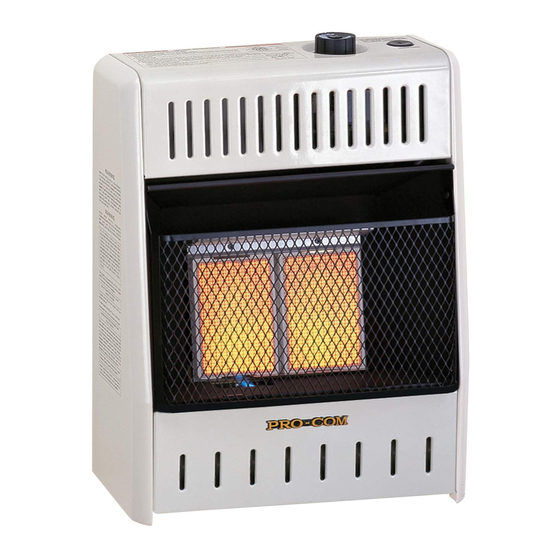
VENT-FREE GAS WALL
HEATER
OWNER'S OPERATION AND
INSTALLATION MANUAL
INFRARED MODELS
MNSD2TPA, MNSD3TPA,
MNSD5TPA
MNSD3TPA-BB MNSD5TPA-BB
PFS
®
US
Advertisement
Chapters
Table of Contents

Related Manuals for Procom MNSD2TPA


Summary of Contents for Procom MNSD2TPA
- Page 1 VENT-FREE GAS WALL HEATER OWNER’S OPERATION AND INSTALLATION MANUAL INFRARED MODELS MNSD2TPA, MNSD3TPA, MNSD5TPA MNSD3TPA-BB MNSD5TPA-BB ® WARNING: If the information in this manual is not followed exactly, a fire or explosion may result causing property damage, personal injury or loss of life.
-
Page 2: Table Of Contents
* Aftermarket: Completion of sale, not for purpose of resale, from the manufacturer. PROCOM HEATING, INC. PATENT INFORMATION This product may be covered by one or more of the following United States patents:... -
Page 3: Safety
SAFETY NATURAL AND PROPANE/LP GAS: Natural IMPORTANT: Read this owner’s and Propane/LP gas are odorless. An odor- manual carefully and completely making agent is added to the gas. The odor before trying to assemble, op- helps you detect a gas leak. However, the erate, or service this heater. - Page 4 SAFETY 1. Do not place Propane/LP supply tank(s) 7. Before using furniture polish, wax, carpet inside any structure. Propane/LP supply cleaner, or similar products, turn heater off. tank(s) must be placed outdoors. If heated, the vapors from these products may create a white powder residue within 2.
-
Page 5: Specifications
SPECIFICATIONS MODEL MNSD2TPA MNSD3TPA MNSD5TPA Ignition Electric Piezo Electric Piezo Electric Piezo Gas Type Natural Gas Natural Gas Natural Gas BTU (available) 10,000 20,000 30,000 Pressure Regulator Setting 6" W.C. 6" W.C. 6" W.C. Maximum 9" Maximum 9" Maximum 9"... -
Page 6: Qualified Installing Agency
QUALIFIED INSTALLING AGENCY Only a qualified agency should install and a) Installing, testing, or replacing gas piping replace gas piping, gas utilization equipment or accessories, and repair and equipment ser- b) Connecting, installing, testing, repairing, vicing. The term “qualified agency” means any or servicing equipment;... -
Page 7: Product Identification
PRODUCT IDENTIFICATION Ignitor Button Control Knob Grill Front Panel Burner Heater Cabinet Figure 1 - Vent-Free Gas Heater UNPACKING 1. Remove heater from carton. 3. Check heater for any shipping damage. If heater is damaged, promptly inform dealer 2. Remove all protective packaging applied where you bought heater. -
Page 8: Air For Combustion And Ventilation
AIR FOR COMBUSTION AND VENTILATION WARNING: This heater shall WARNING: This heater shall not be installed in a room or not be installed in a confined space or unusually tight con- space unless the required vol- ume of indoor combustion air struction unless provisions are provided for adequate combus- is provided by the method de-... - Page 9 AIR FOR COMBUSTION AND VENTILATION VENTILATION AIR Ventilation Air From Inside Building Ventilation Air From Outdoors This fresh air would come from an adjoining Provide extra fresh air by using ventilation unconfined space. When ventilating to an grills or ducts. You must provide two perma- adjoining unconfined space, you must provide nent openings: one within 12"...
-
Page 10: Installation
INSTALLATION NOTICE: This heater is intended CAUTION: This heater cre- for use as supplemental heat. ates warm air currents. These Use this heater along with your currents move heat to wall sur- primary heating system. Do not faces next to heater. Installing install this heater as your pri- heater next to vinyl or cloth wall mary heat source. -
Page 11: Fastening Heater To Wall
INSTALLATION LOCATING HEATER Methods For Attaching Mounting Bracket To Wall This heater is designed to be mounted on a Use only the last hole on each end of mount- wall. For convenience and efficiency, install ing bracket to attach bracket to wall. Attach heater: mounting bracket to a wall only in one of two 1. - Page 12 Only Insert Mounting " Screws Through Last Min. Hole On Each End Figure 8 - Folding Anchor Floor Model: MNSD2TPA " " Min. Figure 9 - Popping Open Anchor Wings For Thin Walls Only Insert Mounting "...
- Page 13 INSTALLATION Installing Bottom Mounting Bracket 6. Replace heater onto mounting bracket. 1. Install bottom bracket to heater bottom 7. Place spacers between bottom mounting with two screws. It may be more conve- holes and wall anchor or drilled hole. nient to remove heater from wall bracket 8.
- Page 14 INSTALLATION GAS SELECTION This appliance is factory INLET GAS PRESSURE preset for propane/LP gas. MAX 1/2 PSIG (3.5 KPA) No changes are required for connecting to propane/LP. Only a qualified installer or service technician can perform gas selec- tion and connecting to gas supply. Gas Connection CAUTION: Two gas line in- Figure 13 - Bottom of Heater...
- Page 15 INSTALLATION 2. Apply thread sealant to the threads on Use only the cap supplied on the the connection fitting. While pushing in, regulator. Do not use an off the rotate the fitting clockwise until the threads shelf pipe plug. This can damage engage the regulator.
- Page 16 INSTALLATION CONNECTING TO GAS SUPPLY CAUTION: For natural gas, WARNING: A qualified ser- check your gas line pressure vice technician must connect before connecting heater to gas heater to gas supply. Follow all line. Gas line pressure must be local codes. no greater than 9"...
-
Page 17: Checking Gas Connections
INSTALLATION Apply pipe joint sealant lightly to male threads. the vent pointing down as shown in Figure This will prevent excess sealant from going 16. Pointing the vent down protects it from into pipe. Excess sealant in pipe could result freezing rain or sleet. - Page 18 INSTALLATION 4. Check all joints of gas supply piping sys- 5. Correct all leaks at once. tem. Apply a noncorrosive leak detection 6. Reconnect heater and equipment shutoff fluid to all joints. If bubbles form, there may valve to gas supply. Check reconnected be a leak.
-
Page 19: Operation
OPERATION FOR YOUR SAFETY READ BEFORE LIGHTING not use any phone in your building. WARNING: If you do not fol- • Immediately call your gas supplier low these instructions exactly, a from a neighbor’s phone. Follow the fire or explosion may result caus- gas supplier’s instructions. -
Page 20: To Turn Off Gas To Appliance
NG, make sure NG pilot burner ig- level between 1 and 5. nites. If input gas type is LP, make sure LP pilot burner ignites. MNSD3TPA MNSD5TPA MNSD2TPA MNSD3TPA-BB MNSD5TPA-BB Burners on HIGH Burners OFF Control Knob Figure 21 - Burner Patterns... -
Page 21: Electrical Connection
ELECTRICAL CONNECTION FOR HEATERS EQUIPPED WITH A BLOWER Do not use this heater if any part of it has been under water. Immediately call a qualified ser- vice technician to inspect the Cover of heater and replace any part of Grounded Grounding Pin Outlet Box... -
Page 22: Inspecting Heater
INSPECTING HEATER IMPORTANT: Owner’s should check pilot flame pattern and burner flame pattern often. Incorrect flame patterns indicate the need for cleaning (see Care and Maintenance, page 23) or service. WARNING: Only a qualified service person should service and repair heater. This includes maintenance requiring replacement or alteration of components. -
Page 23: Care And Maintenance
CARE AND MAINTENANCE WARNING: Turn off heater and let cool before servicing. CAUTION: You must keep control areas, burner, and circulating air passageways of heater clean. Inspect these areas of heater before each use. Have heater inspected yearly by a qualified service techni- cian. -
Page 24: Troubleshooting
TROUBLESHOOTING WARNING: If you smell gas: • Shut off gas supply. • Do not try to light any appliance. • Do not touch any electrical switch; do not use any phone in your building. • Immediately call your gas supplier from a neighbor’s phone. Fol- low the gas supplier’s instructions. - Page 25 TROUBLESHOOTING Problem Possible Cause Corrective Action When ignitor button is 1. Ignitor electrode is posi- 1. Replace pilot assembly. pressed in, there is no tioned wrong. Ignitor elec- spark at ODS/pilot. trode is broken. 2. Ignitor electrode is not con- 2.
- Page 26 TROUBLESHOOTING Problem Possible Cause Corrective Action Burner(s) does not light 1. Burner orifice is clogged. 1. Clean burner orifice (see after ODS/pilot is lit. Care and Maintenance, page 23) or replace burner orifice. 2. Burner orifice diameter is too 2. Replace burner orifice. small.
- Page 27 TROUBLESHOOTING Problem Possible Cause Corrective Action Heater produces a click- 1. Metal is expanding while 1. This is common with most ing/ticking noise just after heating or contracting while heaters. If noise is exces- burner is lit or shut off. cooling.
-
Page 28: Replacement Parts
• Purchase date ACCESSORIES Purchase these heater accessories from your local dealer. If they can not supply these acces- sories, contact ProCom Heating, Inc. at 1-866-573-0674 for information. EQUIPMENT SHUTOFF VALVE For all models. Equipment shutoff valve with 1/8” NPT tap. -
Page 29: Service Hints
TECHNICAL SERVICE You may have further questions about installation, operation, or troubleshooting. If so, contact ProCom Heating, Inc. at 1-866-573-0674. When calling, please have your model and serial numbers of your heater ready. www.usaprocom.com... -
Page 30: Parts
PARTS MODEL MNSD2TPA www.usaprocom.com 200218-01A... - Page 31 PARTS MODEL MNSD2TPA This list contains replaceable parts for your heater. When ordering replacement parts, follow the instructions listed under Replacement Parts on page 28 of this manual. ITEM PART # DESCRIPTION Cabinet Assembly Reflector MB29003 Grill Guard MB09003 Lower Front Panel...
- Page 32 PARTS MODELS MNSD3TPA & MNSD3TPA-BB www.usaprocom.com 200218-01A...
- Page 33 PARTS MODELS MNSD3TPA & MNSD3TPA-BB This list contains replaceable parts for your heater. When ordering replacement parts, follow the instructions listed under Replacement Parts on page 28 of this manual. ITEM MNSD3TPA MNSD3TPA-BB DESCRIPTION Cabinet Assembly Reflector MB29002 MB29002 Grill Guard MB09002 MB09002 Lower Front Panel...
- Page 34 PARTS MODELS MNSD5TPA & MNSD5TPA-BB www.usaprocom.com 200218-01A...
- Page 35 PARTS MODELS MNSD5TPA & MNSD5TPA-BB This list contains replaceable parts for your heater. When ordering replacement parts, follow the instructions listed under Replacement Parts on page 28 of this manual. ITEM MNSD5TPA MNSD5TPA-BB DESCRIPTION Cabinet Assembly Reflector MB29001 MB29001 Grill Guard MB09051 MB09051 Lower Front Panel...
-
Page 36: Warranty
We make no other warranty, expressed or implied. LIMITED WARRANTY ProCom Heating, Inc. warrants this product to be free from defects in materials and components for ONE (1) year from the date of first purchase, provided that the product has been properly installed by a qualified installer in accordance with all local codes and instructions furnished with the unit, operated and main- tained in accordance with all applicable instructions. - Page 37 CALENTADOR DE GAS DE PARED SIN VENTILAS MANUAL DE FUNCIONAMIENTO E INSTALACIÓN DEL PROPIETARIO INFRARROJO MODELOS MNSD2TPA, MNSD3TPA, MNSD5TPA MNSD3TPA-BB MNSD5TPA-BB ADVERTENCIA: Este aparato está equipado para funcionar con gas (natural y propano). No se permite convertir más que a gas ®...
- Page 38 TABLA DE CONTENIDOS Seguridad ..........39 Funcionamiento ........56 Especificaciones ........41 Conexión Eléctrica........59 Agencia de Instalación Calificada.... 42 Cableado Eléctrico ........59 Características del Producto ....42 Inspección del calentador ......60 Normas Locales........42 Cuidado y mantenimiento ......61 Identificación del Producto ......
-
Page 39: Seguridad
SEGURIDAD de la gripe, con dolores de cabeza, mareos IMPORTANTE: Lea este manual del y/o náusea. Si usted presenta estos síntomas, propietario cuidadosa y completa- es posible que el calentador no esté funcio- mente antes de intentar ensamblar, nando correctamente. ¡Respire aire fresco operar o dar servicio a este calen- inmediatamente! Haga que le den servicio al calentador. - Page 40 Esto asegurará aire suficiente para la combustión.. PROCOM HEATING, INC. INFORMACIÓN DE PATENTES Este producto puede estar cubierto por una o más de las siguientes patentes de Estados Unidos: 8,915,239 8,851,065 8,764,436 8,757,202 8,757,13 8,752,541 8,568,136 8,545,216...
-
Page 41: Especificaciones
ESPECIFICACIONES MODELO MNSD2TPA MNSD3TPA MNSD5TPA Encendido Piezoeléctrico Piezoeléctrico Piezoeléctrico Tipo de gas Con gas natural Con gas natural Con gas natural BTU (disponible) 10,000 20,000 30,000 Ajuste del regulador de presión: 6" de c.a. 6" de c.a. 6" de c.a. -
Page 42: Agencia De Instalación Calificada
AGENCIA DE INSTALACIÓN CALIFICADA La instalación y el remplazo de tuberías de a) Instalar, probar o remplazar tuberías de gas, de equipos o de accesorios para la gas o utilización de gas y la reparación y el mante- b) Conectar, instalar, probar, reparar o reali- nimiento de los equipos deben estar a cargo zar mantenimiento de equipos;... -
Page 43: Identificación Del Producto
IDENTIFICACIÓN DEL PRODUCTO Botón de Perilla de encendido control Rejilla Panel anterior Quemador Gabinete del calentador Figura 1 - Calentador de gas sin ventilación DESEMPAQUE 1. Saque el calentador de la caja. 3. Revise el calentador para ver si hay algún daño debido al transporte. -
Page 44: Aire Para Combustión Y Ventilación
AIRE PARA COMBUSTIÓN Y VENTILACIÓN ADVERTENCIA: Este calen- ADVERTENCIA: Este calen- tador no se debe instalar en un tador no se debe instalar en una espacio reducido o excepcional- habitación o espacio a menos mente hermético a menos que se que el volumen requerido de aire tomen las precauciones necesa- de combustión en interiores es... - Page 45 AIRE PARA COMBUSTIÓN Y VENTILACIÓN AIRE PARA VENTILACIÓN Aire del interior de la construcción Aire del exterior para ventilación para ventilación Proporcione aire fresco adicional mediante Este aire fresco viene de un espacio adyacente el uso de rejillas o conductos de ventilación. no confinado.
-
Page 46: Instalación
INSTALACIÓN AVISO: Este calentador está ADVERTENCIA: Nunca ins- diseñado para utilizarse como tale el calentador calefacción adicional. Use este • en un dormitorio o baño calentador junto con su sistema • en un vehículo recreativo de calefacción principal. No • donde cortinas, muebles, ropa instale este calentador como u otros objetos inflamables fuente de calefacción principal. - Page 47 INSTALACIÓN DISTANCIA DE SEPARACIÓN DE COLOCACIÓN DEL COMBUSTIBLES CALENTADOR EN LA PARED Siga con atención las siguientes instruc- Soporte de montaje ciones. Este calentador es una unidad de El soporte de montaje se encuentra en el pa- montaje en la pared diseñada para apoyarse nel posterior del calentador (consulte la Figura directamente sobre el suelo o una base de 5).
- Page 48 2. Fijación a anclajes de pared: este mé- todo le permite fijar el soporte de montaje Piso en paredes huecas (las áreas de la pared que se encuentran entre los maderos) o Modelo: MNSD2TPA en paredes sólidas (de concreto o mam- 27 cm (10 ") postería).
- Page 49 INSTALACIÓN Método de fijación a viga de pared IMPORTANTE: ¡no golpee la llave con un Para fijar el soporte de montaje a las vigas martillo! Para paredes gruesas, de más de de pared: 1.3 cm (1/2") de ancho, o paredes sólidas, no abra las alas.
- Page 50 INSTALACIÓN Instalación de los tornillos de 6. Vuelva a colocar el calentador en el soporte montaje inferiores de montaje. 1. Instale el soporte base en la parte inferior 7. Coloque los separadores entre los orificios del calentador con dos tornillos. Puede de montaje inferiores y el anclaje de pared ser más cómodo retirar el calentador del o el orificio que perforó.
- Page 51 INSTALACIÓN SELECCIÓN DE GAS Este aparato viene ajustado INLET GAS PRESSURE MAX 1/2 PSIG (3.5 KPA) de fábrica para gas propano/ LP. No se requieren cambios para la conexión a propano/ Conexión de gas LP. Sólo un instalador o técnico de servicio calificado puede Figura 13 - Parte inferior del calentador realizar la selección de gas y la...
- Page 52 INSTALACIÓN 2. Aplique sellador de roscas a las roscas en el Utilice solamente el tapón su- accesorio de conexión. Mientras presiona, gire ministrado en el regulador. No hacia la derecha el ajuste hasta que las roscas utilice un fuera el tapón del tubo se acoplan al regulador.
- Page 53 INSTALACIÓN CONEXIÓN AL SUMINISTRO DE GAS ADVERTENCIA: Una per- PRECAUCIÓN: Para gas sona de servicio capacitada propano/LP, nunca conecte el debe conectar el calentador al calentador directamente al sumi- suministro de gas. Siga todas nistro de gas propano/LP. Este las normas locales. calentador requiere un regulador externo (no se incluye).
- Page 54 INSTALACIÓN Antes de instalar el calentador, asegúrese IMPORTANTE: instale una válvula de cierre de tener los elementos que se indican a del equipo en un lugar que sea accesible. La continuación. válvula de cierre del equipo es para abrir o •...
- Page 55 INSTALACIÓN REVISIÓN DE LAS CONEXIONES DE GAS ADVERTENCIA: Nunca use ADVERTENCIA: Después una llama al descubierto para de instalar el calentador o de verificar si hay fugas. Aplique lí- darle servicio, pruebe todas las quido no corrosivo para detectar conexiones y tubos de gas de fugas en todas las uniones.
-
Page 56: Funcionamiento
INSTALACIÓN 4. Revise todas las uniones entre la válvula 6. Encienda el calentador (consulte Funcio- de cierre del equipo y válvula de control namiento). Revise el resto de las uniones (consulte la figura 18 o 19). Aplique en internas para ver si hay fugas. todas las uniones algún líquido para 7. - Page 57 FUNCIONAMIENTO INSTRUCCIONES DE ENCENDIDO 1. ¡ALTO! Lea la información de seguridad piloto. El piloto está instalado en la parte en la página 56. anterior del quemador. El piloto puede ser visto a través de la parrilla En caso ne- 2. Asegúrese de que la válvula de cierre del cesario, continúe oprimiendo el botón de equipo esté...
- Page 58 FUNCIONAMIENTO MNSD3TPA MNSD5TPA MNSD2TPA MNSD3TPA-BB MNSD5TPA-BB Quemadores de ALTA Quemadors apagado Perilla de control Figura 21 - Patrón del quemador FUNCIONAMIENTO DEL CONTROL CON TERMOSTATO El control termostático utilizado en este mo- quemador volverá a encenderse cuando la delo difiere de termostatos estándar. Usted temperatura ambiente desciende por debajo establece termostatos estándar a una tem-...
-
Page 59: Conexión Eléctrica
CONEXIÓN ELÉCTRICA PARA CALENTADORES EQUIPADO CON UN VENTILADOR nentemente a tierra, puede ser a través de No utilice este calentador una caja de un toma corriente correctamente conectado a tierra. El adaptador no se debe si alguna de sus piezas estuvo usar si hay disponible un receptáculo de sumergida en agua. -
Page 60: Inspección Del Calentador
INSPECCIÓN DEL CALENTADOR IMPORTANTE: El propietario debe revisar frecuentemente los patrones de la llama del piloto y de la llama del quemador. Patrones de llama incorrectos indican la necesidad de limpieza o servicio de mantenimiento (consulte Cuidado y mantenimiento, página 61). ADVERTENCIA: Sólo una persona de servicio capacitada debe repararlo o darle servicio. -
Page 61: Cuidado Y Mantenimiento
CUIDADO Y MANTENIMIENTO ADVERTENCIA: Apague el calentador y deje que se enfríe antes de darle mantenimiento. PRECAUCIÓN: Debe mantener limpias las áreas de control, el quemador y las vias de circulación de aire del calentador. Inspec- cione estas áreas del calentador antes de cada uso. Haga que una persona de servicio calificada inspeccione el calentador una vez al año. -
Page 62: Solución De Problemas
SOLUCIÓN DE PROBLEMAS ADVERTENCIA: Si percibe olor a gas • Cierre el suministro de gas. • No intente encender ningún aparato. • No toque ningún interruptor eléctrico; no use ningún teléfono en el edificio. • Llame inmediatamente a su proveedor de gas desde el teléfono de algún vecino. - Page 63 SOLUCIÓN DE PROBLEMAS Problema Causa Posible Acción correctiva Cuando se presiona el 1. Electrodo de encendido 1. Remplace el electrodo del botón del encendedor, no está mal colocado. Electro- encendedor. hay chispa en el piloto/ do de encendido está roto. ODS.
- Page 64 SOLUCIÓN DE PROBLEMAS Problema Causa Posible Acción correctiva El piloto/ODS se en- 1. La perilla de control no está 1. Presione la perilla de control ciende pero la llama se presionada completamente. completamente. extingue cuando la perilla 2. La perilla de control no se 2.
- Page 65 SOLUCIÓN DE PROBLEMAS Problema Causa Posible Acción correctiva Llamas amarillas alta 1. No hay suficiente aire. 1. Revise el quemador en busca durante la combustión de polvo y residuos. Si los hay, en el quemador. limpie el quemador (consulte Cuidado y mantenimiento, en la página 61).
- Page 66 SOLUCIÓN DE PROBLEMAS Problema Causa Posible Acción correctiva El calentador produce 1. En el calentador se están 1. Abra la ventana para ventilar olores no deseados. quemado vapores prove- la habitación. Deje de utilizar nientes de pintura, fijador los productos que ocasionan para el cabello, pegamen- el olor mientras el calentador tos, productos de limpieza,...
-
Page 67: Consejos Para Servicio
Es posible que tenga preguntas adicionales sobre la instalación, el funcionamiento o la solución de problemas. De ser así, póngase en contacto con ProCom Heating, Inc. al 1-866-573-0674. Al llamar tenga a la mano los números de modelo y serie de su calentador. -
Page 68: Piezas
PIEZAS MODELO MNSD2TPA www.usaprocom.com 200218-01A... - Page 69 PIEZAS MODELO MNSD2TPA Esta lista contiene las piezas remplazables utilizadas en el calentador. Al hacer un pedido de piezas, siga las instrucciones listadas en Piezas de repuesto en la página 74 de este manual. Art. Piezo # Descripción Cant. Asamblea de gabinete...
- Page 70 PIEZAS MODELOS MNSD3TPA Y MNSD3TPA-BB www.usaprocom.com 200218-01A...
- Page 71 PIEZAS MODELOS MNSD3TPA Y MNSD3TPA-BB Esta lista contiene las piezas remplazables utilizadas en el calentador. Al hacer un pedido de piezas, siga las instrucciones listadas en Piezas de repuesto en la página 74 de este manual. Art. MNSD3TPA MNSD3TPA-BB Descripción Cant.
- Page 72 PIEZAS MODELOS MNSD5TPA Y MNSD5TPA-BB www.usaprocom.com 200218-01A...
- Page 73 PIEZAS MODELOS MNSD5TPA Y MNSD5TPA-BB Esta lista contiene las piezas remplazables utilizadas en el calentador. Al hacer un pedido de piezas, siga las instrucciones listadas en Piezas de repuesto en la página 74 de este manual. Art. MNSD5TPA MNSD5TPA-BB Descripción Cant.
-
Page 74: Piezas De Repuesto
PIEZAS DE REPUESTO Nota: use sólo piezas de repuesto originales. Esto protegerá la cobertura de su garantía para partes remplazadas bajo la garantía. PIEZAS CON GARANTÍA Comuníquese con los distribuidores autoriza- • los números de modelo y de serie de su dos de este producto. -
Page 75: Accesorios
ACCESORIOS Adquiera estos accesorios con su distribuidor local. Si no pueden proporcionarle estos ac- cesorios, comuníquese ProCom Heating, Inc. al 1-866-573-0674 para obtener información. VÁLVULA DE INTERRUPCIÓN DE EQUIPOS Para todos los modelos. Válvula de interrupción de equipos con 1/8". Llave de paso del TNP. -
Page 76: Garantía
No hacemos ninguna otra garantía, expresa o implícita. GARANTÍA LIMITADA ProCom Heating, Inc. garantiza que este producto está libre de defectos en materiales y componentes por un 1 año desde la fecha de la primera compra, siempre que el producto ha sido correctamente instalado por personal calificado de conformidad con todos los códigos locales e instrucciones de la unidad, opera-...
Need help?
Do you have a question about the MNSD2TPA and is the answer not in the manual?
Questions and answers
Propane gas assembly specs and setup Instructions
The ProCom MNSD2TPA heater operates with propane gas and has the following specifications:
- BTU Output: 10,000 BTU
- Regulator Pressure Setting: 10 inches of water column (c.a.)
- Gas Inlet Pressure:
- Maximum: 14 inches of water column (c.a.)
- Minimum: 11 inches of water column (c.a.)
- Ignition Type: Piezoelectric
For setup and installation:
- Ensure the heater is equipped for propane gas use.
- Follow the installation instructions in the manual.
- Do not attempt field conversion between gas types.
- Installation and service must be performed by a qualified installer, service agency, or gas supplier.
- Follow safety precautions, including avoiding the use of flammable vapors near the unit.
This answer is automatically generated