Table of Contents
Advertisement
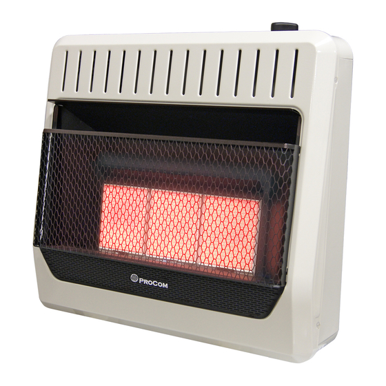
VENT-FREE GAS WALL HEATER
OWNER'S OPERATION AND
INSTALLATION MANUAL
INFRARED MODELS
MN2PHG, MN2PTG, MN3PHG, MN3PTG
ML2PHG, ML2PTG, ML3PHG, ML3PTG
PFS
WARNING: If the information in this manual is not
followed exactly, a fire or explosion may result causing
property damage, personal injury or loss of life.
— Do not store or use gasoline or other flammable va-
pors and liquids in the vicinity of this or any other
appliance.
— WHAT TO DO IF YOU SMELL GAS
• Do not try to light any appliance.
• Do not touch any electrical switch; do not use any
phone in your building.
• Immediately call your gas supplier from a neighbor's
phone. Follow the gas supplier's instructions.
• If you cannot reach your gas supplier, call the fire
department.
— Installation and service must be performed by a quali-
fied installer, service agency or the gas supplier.
WARNING: This appliance is equipped for Natural and
Propane gas. Field conversion is not permitted other than
between natural or propane gases.
Questions, problems, missing parts? Before returning to your retailer, call
our customer service department at 1-866-573-0674, 7:30 am - 4:15 pm CST,
Monday through Friday or email customerservice@usaprocom.com
®
US
30,000 Btu/Hr
Model Shown
Advertisement
Table of Contents

Related Manuals for Procom PFS MN2PHG


Summary of Contents for Procom PFS MN2PHG
- Page 1 VENT-FREE GAS WALL HEATER OWNER’S OPERATION AND INSTALLATION MANUAL INFRARED MODELS MN2PHG, MN2PTG, MN3PHG, MN3PTG ML2PHG, ML2PTG, ML3PHG, ML3PTG ® 30,000 Btu/Hr Model Shown WARNING: If the information in this manual is not followed exactly, a fire or explosion may result causing property damage, personal injury or loss of life.
-
Page 2: Table Of Contents
TABLE OF CONTENTS Safety ............3 Operation ..........17 Qualified Installing Agency ......4 Inspecting Burners........21 Product Features ........4 Care And Maintenance ......22 Specifications ..........5 Troubleshooting ........23 Local Codes..........7 Technical Service........25 Preparing For Installation ......7 Parts ............ -
Page 3: Safety
SAFETY NATURAL AND PROPANE/LP GAS: Natural IMPORTANT: Read this owner’s and Propane/LP gas are odorless. An odor- manual carefully and completely making agent is added to the gas. The odor before trying to assemble, op- helps you detect a gas leak. However, the erate, or service this heater. -
Page 4: Qualified Installing Agency
SAFETY 1. Do not place Propane/LP supply tank(s) 7. Before using furniture polish, wax, carpet inside any structure. Propane/LP supply cleaner, or similar products, turn heater tank(s) must be placed outdoors. off. If heated, the vapors from these prod- ucts may create a white powder residue 2. -
Page 5: Specifications
SPECIFICATIONS MODEL MN2PHG MN2PTG Ignition Piezo Piezo Gas Type Natural Gas Natural Gas BTU (available) 20,000 20,000 Pressure Regulator Setting 6" W.C. 6" W.C. Maximum 10.5" Maximum 10.5" Inlet Gas Pressure* (inches of water) Minimum 7" Minimum 7" Heater Dimensions (HxWxD) 24"... - Page 6 SPECIFICATIONS MODEL ML2PHG ML2PTG Ignition Piezo Piezo Gas Type Propane/LP Propane/LP BTU (available) 18,000 18,000 Pressure Regulator Setting 10" W.C. 10" W.C. Maximum 14" Maximum 14" Inlet Gas Pressure* (inches of water) Minimum 11" Minimum 11" Heater Dimensions (HxWxD) 24" × 18 "...
-
Page 7: Local Codes
LOCAL CODES Install and use heater with care. Follow all State of Massachusetts: The installation local codes. In the absence of local codes, must be made by a licensed plumber or use the latest edition of The National Fuel gas fitter in the Commonwealth of Mas- Gas Code, ANSI Z223.1/NFPA 54*. -
Page 8: Air For Combustion And Ventilation
UNPACKING 1. Remove heater from carton. 3. Check heater for any shipping damage. If heater is damaged, promptly inform dealer 2. Remove all protective packaging applied where you bought heater. to heater for shipping WATER VAPOR: A BY-PRODUCT OF UNVENTED ROOM HEATERS Water vapor is a by-product of gas combus- The following steps will help ensure that water tion. - Page 9 AIR FOR COMBUSTION AND VENTILATION VENTILATION AIR Ventilation Air From Inside Building Ventilation Air From Outdoors Provide extra fresh air by using ventilation This fresh air would come from an adjoining grills or ducts. You must provide two perma- unconfined space. When ventilating to an nent openings: one within 12"...
-
Page 10: Installation
INSTALLATION NOTICE: This heater is intended CAUTION: This heater cre- for use as supplemental heat. ates warm air currents. These Use this heater along with your currents move heat to wall sur- primary heating system. Do not faces next to heater. Installing install this heater as your pri- heater next to vinyl or cloth wall mary heat source. - Page 11 INSTALLATION LOCATING HEATER This heater is designed to be mounted on a wall. For convenience and efficiency, install heater: 1. Where there is easy access for operation, inspection, and service. 2. In the coldest part of room. When installing the appliance directly on car- Screw peting, tile or other combustible material other Front...
- Page 12 INSTALLATION 2. Mark screw locations on wall (see Fig- holes drilled in wall. ure 7). Note: Mark only last hole on each 3. Insert mounting screws through bracket end of mounting bracket. Insert mounting and into wall studs. screws through these holes only. 4.
- Page 13 INSTALLATION Placing Heater On Mounting 5. Replace heater onto mounting bracket. Bracket 6. Place spacers between bottom mounting 1. Locate two horizontal slots on back panel holes and wall anchor or drilled hole. of heater (see Figure 10). 7. Hold spacer in place with one hand. With other 2.
- Page 14 INSTALLATION CONNECTING TO GAS SUPPLY WARNING: A qualified ser- CAUTION: For propane/LP vice technician must connect gas, Never connect heater directly to the gas supply. This heater heater to gas supply. Follow all requires an external regulator local codes. (not supplied). Install the external WARNING: This appliance regulator between the heater and requires a 3/8"...
- Page 15 INSTALLATION Apply pipe joint sealant lightly to male threads. as shown in Figure 13. Pointing the vent down This will prevent excess sealant from going protects it from freezing rain or sleet. into pipe. Excess sealant in pipe could result Install sediment trap in supply line as shown in clogged heater valves.
- Page 16 INSTALLATION CHECKING GAS CONNECTIONS WARNING: Test all gas piping WARNING: Never use an open and connections for leaks after flame to check for a leak. Apply a installing or servicing. Correct mixture of liquid soap and water all leaks at once. to all joints.
-
Page 17: Operation
INSTALLATION PRESSURE TESTING HEATER GAS CONNECTIONS 1. Open equipment shutoff valve (see Fig- 5. Correct all leaks at once. ure 14, page 16). 6. Light heater (see Lighting Instructions on 2. Open gas supply tank valve. page 17 or 19). Check all other internal joints for leaks. - Page 18 OPERATION 7. Keep control knob pressed in for 30 8. Turn control knob counterclockwise seconds after lighting pilot. After 30 to desired heating level. The main burner seconds, release control knob. If control should light. Set control knob at LOW, knob does not pop up when released, MED or HIGH locked positions.
- Page 19 OPERATION THERMOSTAT MODELS LIGHTING INSTRUCTIONS 1. STOP! Read the safety information on Note: If pilot goes out, repeat steps 3 page 17. through 7. This heater has a safety inter- lock system. Wait one (1) minute before 2. Make sure equipment shutoff valve is fully lighting pilot again.
- Page 20 OPERATION THERMOSTAT CONTROL OPERATION The thermostatic control used on these mod- exceed the set temperature. If so, the burner els differ from standard thermostats. Standard will shut off. The burner will cycle back on thermostats simply turn the burner on and off. when room temperature drops below the set The thermostat used on this heater senses temperature.
-
Page 21: Inspecting Burners
INSPECTING BURNERS IMPORTANT: Owner’s should check pilot flame pattern and burner flame pattern often. Incorrect flame patterns indicate the need for cleaning (see Care and Maintenance, page 22) or service. WARNING: Only a qualified service person should service and repair heater. This includes maintenance requiring replacement or alteration of components. -
Page 22: Care And Maintenance
CARE AND MAINTENANCE WARNING: Turn off heater and let cool before servicing. CAUTION: You must keep control areas, burner, and circulating air passageways of heater clean. Inspect these areas of heater before each use. Have heater inspected yearly by a qualified service techni- cian. -
Page 23: Troubleshooting
TROUBLESHOOTING WARNING: If you smell gas: • Shut off gas supply. • Do not try to light any appliance. • Do not touch any electrical switch; do not use any phone in your building. • Immediately call your gas supplier from a neighbor’s phone. Fol- low the gas supplier’s instructions. - Page 24 TROUBLESHOOTING Problem Possible Cause Corrective Action ODS/pilot lights but flame 1. Control knob is not fully 1. Press in control knob fully. goes out when control pressed in. knob is released. 2. Control knob is not pressed 2. After ODS/pilot lights, keep in long enough.
-
Page 25: Technical Service
Ventilation require- ments, page 8. TECHNICAL SERVICE You may have further questions about installation, operation, or troubleshooting. If so, contact ProCom Heating, Inc. at 1-866-573-0674. When calling, please have your model and serial numbers of your heater ready. www.usaprocom.com 200317-01C... -
Page 26: Parts
PARTS MODELS MN2PHG, ML2PHG, MN3PHG, ML3PHG 30,000 BTU/Hr Heater Shown www.usaprocom.com 200317-01C... - Page 27 PARTS MODELS MN2PHG, ML2PHG, MN3PHG, ML3PHG This list contains replaceable parts for your heater. When ordering replacement parts, follow the instructions listed under Replacement Parts on page 30 of this manual. ITEM MN2PHG ML2PHG DESCRIPTION Back Body Panel 161132-01 161132-01 Mounting Bracket 161133-01 161133-01...
- Page 28 PARTS MODELS MN2PTG, ML2PTG, MN3PTG, ML3PTG 30,000 BTU/Hr Heater Shown www.usaprocom.com 200317-01C...
- Page 29 PARTS MODELS MN2PTG, ML2PTG, MN3PTG, ML3PTG This list contains replaceable parts for your heater. When ordering replacement parts, follow the instructions listed under Replacement Parts on page 30 of this manual. ITEM MN2PTG ML2PTG DESCRIPTION Back Body Panel 161132-01 161132-01 Mounting Bracket 161133-01 161133-01...
-
Page 30: Replacement Parts
REPLACEMENT PARTS Note: Use only original replacement parts. This will protect your warranty coverage for parts replaced under warranty. PARTS UNDER WARRANTY Contact authorized dealers of this product. • Model and serial number of your heater If they can’t supply original replacement •... -
Page 31: Accessories
ACCESSORIES Purchase these heater accessories from your local dealer. If they can not supply these acces- sories, contact ProCom Heating, Inc. at 1-866-573-0674 for information. EQUIPMENT SHUTOFF VALVE For all models. Equipment shutoff valve with 1/8" NPT tap. OPTIONAL FAN KIT - MGB100 The optional fan has 3 settings AUTO/OFF/MAN. -
Page 32: Warranty
We make no other warranty, expressed or implied. LIMITED WARRANTY ProCom Heating, Inc. warrants this product to be free from defects in materials and components for ONE (1) year from the date of first purchase, provided that the product has been properly installed by a qualified installer in accordance with all local codes and instructions furnished with the unit, operated and main- tained in accordance with all applicable instructions.
Need help?
Do you have a question about the PFS MN2PHG and is the answer not in the manual?
Questions and answers