Table of Contents
Advertisement
Available languages
Available languages
WARNING: If the information in this manual is not
followed exactly, a fire or explosion may result causing
property damage, personal injury or loss of life.
— Do not store or use gasoline or other flammable va-
pors and liquids in the vicinity of this or any other
appliance.
— WHAT TO DO IF YOU SMELL GAS
• Do not try to light any appliance.
• Do not touch any electrical switch; do not use any
phone in your building.
• Immediately call your gas supplier from a neighbor's
phone. Follow the gas supplier's instructions.
• If you cannot reach your gas supplier, call the fire
department.
— Installation and service must be performed by a quali-
fied installer, service agency or the gas supplier.
INSTALLER: Leave this manual with the appliance.
CONSUMER: Retain this manual for future reference.
Questions, problems, missing parts? Before returning to your retailer, call
our customer service department at 1-866-573-0674, 8:00 am - 4:45 pm CST,
Monday through Friday or email contact@usaprocom.com
VENT-FREE PROPANE/LP GAS
SPACE HEATER
OWNER'S OPERATION AND
INSTALLATION MANUAL
INFRARED MODELS
ML1PHG, MN1PHG
ML1PTG, MN1PTG
Advertisement
Chapters
Table of Contents

Subscribe to Our Youtube Channel
Related Manuals for Procom ML1PHG


Summary of Contents for Procom ML1PHG
- Page 1 VENT-FREE PROPANE/LP GAS SPACE HEATER OWNER’S OPERATION AND INSTALLATION MANUAL INFRARED MODELS ML1PHG, MN1PHG ML1PTG, MN1PTG WARNING: If the information in this manual is not followed exactly, a fire or explosion may result causing property damage, personal injury or loss of life.
-
Page 2: Table Of Contents
TABLE OF CONTENTS Safety ............3 Installation ..........8 Specifications ..........4 Operation ..........14 Product Identification ......... 5 Inspecting Burners........17 Qualified Installing Agency ......5 Care And Maintenance ......18 Product Features ........5 Troubleshooting ........19 Air For Combustion and Ventilation ... 6 Replacement Parts ........ -
Page 3: Safety
SAFETY NATURAL AND PROPANE GAS: Natural and IMPORTANT: Read this owner’s Propane gas are odorless. An odor-making manual carefully and completely agent is added to the gas. The odor helps you before trying to assemble, op- detect a gas leak. However, the odor added to erate, or service this heater. -
Page 4: Specifications
12. To prevent performance problems, do not use propane fuel tank of less than 100 lbs. • Where flammable liquids or vapors are capacity. used or stored. • Under dusty conditions. SPECIFICATIONS MODEL MN1PHG ML1PHG MN1PTG ML1PTG Ignition Piezo Piezo Piezo Piezo Gas Type... -
Page 5: Product Identification
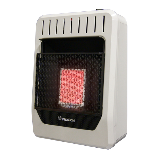
PRODUCT IDENTIFICATION Ignitor Button Control Knob Grill Burner Front Panel Heater Cabinet Figure 1 - Vent-Free Gas Heater QUALIFIED INSTALLING AGENCY Only a qualified agency should install and a) Installing, testing, or replacing gas piping replace gas piping, gas utilization equipment or accessories, and repair and equipment ser- b) Connecting, installing, testing, repairing, vicing. -
Page 6: Air For Combustion And Ventilation
LOCAL CODES Install and use heater with care. Follow all State of Massachusetts: The installation local codes. In the absence of local codes, must be made by a licensed plumber or use the latest edition of The National Fuel gas fitter in the Commonwealth of Mas- Gas Code, ANSI Z223.1/NFPA 54*. - Page 7 AIR FOR COMBUSTION AND VENTILATION Exhaust fans, fireplaces, clothes dryers and fuel burning appliances draw air from the house to operate. You must provide adequate fresh air for these appliances. This will insure proper venting of vented fuel-burning appliances. WARNING: This heater shall not be installed in a room or space unless the required volume of indoor combustion air is provided by the method described in the National Fuel Gas Code, ANSI Z223.1/ NFPA 54, the International Fuel Gas Code, or applicable local codes.
-
Page 8: Installation
INSTALLATION NOTICE: This heater is intended CAUTION: This heater cre- for use as supplemental heat. ates warm air currents. These Use this heater along with your currents move heat to wall sur- primary heating system. Do not faces next to heater. Installing install this heater as your pri- heater next to vinyl or cloth wall mary heat source. - Page 9 INSTALLATION LOCATING HEATER Methods For Attaching Mounting Bracket To Wall This heater is designed to be mounted on a Use only the last hole on each end of mount- wall. For convenience and efficiency, install ing bracket to attach bracket to wall. Attach heater: mounting bracket to a wall only in one of two 1.
- Page 10 INSTALLATION Attaching Mounting Bracket To Placing Heater On Mounting Wall Bracket Note: Wall anchors, mounting screws, and 1. Locate two horizontal slots on back panel spacers are in hardware package. The hard- of heater (see Figure 9). ware package is provided with heater. 2.
- Page 11 INSTALLATION Follow steps 1 through 4 under Attaching bottom mounting hole and spacer. Place To Wall Anchor Method, page 10. If install- tip of screw in opening of wall anchor or ing bottom mounting screw into wall stud, drilled hole. drill holes at marked locations using 9/64"...
- Page 12 INSTALLATION Before installing heater, make sure you have IMPORTANT: Install an equipment shutoff the items listed below: valve in an accessible location. The equip- • piping (check local codes) ment shutoff valve is for turning on or shutting • sealant (resistant to natural gas and pro- off the gas to the appliance.
- Page 13 INSTALLATION CHECKING GAS CONNECTIONS 3. Check all joints from gas meter to equip- WARNING: Test all gas piping ment shutoff valve for natural gas or and connections for leaks after propane supply to equipment shutoff valve installing or servicing. Correct for propane (see Figure 14 or 15).
-
Page 14: Operation
OPERATION FOR YOUR SAFETY READ BEFORE LIGHTING • Do not touch any electric switch; do WARNING: If you do not fol- not use any phone in your building. low these instructions exactly, • Immediately call your gas supplier a fire or explosion may result from a neighbor’s phone. - Page 15 OPERATION 8. Partially press down control knob and Ignitor Electrode Thermocouple turn counterclockwise . Release the downward pressure on the knob while Pilot Burner continuing to turn until the knob locks at the locked ON position. The main burner should light. Do not operate between locked positions.
- Page 16 OPERATION THERMOSTAT CONTROL OPERATION The thermostatic control used on these mod- Note: The thermostat sensing bulb measures els differ from standard thermostats. Standard the temperature of air near the heater cabinet. thermostats simply turn the burner on and off. This may not always agree with room tem- The thermostat used on this heater senses perature (depending on housing construction, the room temperature.
-
Page 17: Inspecting Burners
INSPECTING BURNERS IMPORTANT: Owner’s should check pilot flame pattern and burner flame pattern often. Incorrect flame patterns indicate the need for cleaning (see Care and Maintenance, page 18) or service. WARNING: Only a qualified service person should service and repair heater. This includes maintenance requiring replacement or alteration of components. -
Page 18: Care And Maintenance
CARE AND MAINTENANCE WARNING: Turn off heater and let cool before servicing. CAUTION: You must keep control areas, burner, and circulating air passageways of heater clean. Inspect these areas of heater before each use. Have heater inspected yearly by a qualified service techni- cian. -
Page 19: Troubleshooting
TROUBLESHOOTING WARNING: If you smell gas: • Shut off gas supply. • Do not try to light any appliance. • Do not touch any electrical switch; do not use any phone in your building. • Immediately call your gas supplier from a neighbor’s phone. Fol- low the gas supplier’s instructions. - Page 20 TROUBLESHOOTING Problem Possible Cause Corrective Action ODS/pilot lights but flame 1. Control knob is not fully 1. Press in control knob fully. goes out when control pressed in. knob is released. 2. Control knob is not pressed 2. After ODS/pilot lights, keep in long enough.
- Page 21 TROUBLESHOOTING Problem Possible Cause Corrective Action Gas odor during com- 1. Foreign matter between 1. Take apart gas tubing and bustion. control valve and burner. remove foreign matter. 2. Gas leak. (See Warning 2. Locate and correct all leaks Statement at top of page 19). (see Checking Gas Connec- tions, page 13).
- Page 22 PARTS This list contains replaceable parts for your heater. When ordering replacement parts, follow the instructions listed under Replacement Parts on page 23 of this manual. MODELS MN1PHG & ML1PHG ITEM PART # DESCRIPTION 161132-01 Mounting Bracket ML083-03 Piezo Ignitor...
-
Page 23: Replacement Parts
• Purchase date ACCESSORIES Purchase these heater accessories from your local dealer. If they can not supply these acces- sories, contact ProCom Heating, Inc. at 1-866-573-0674 for information. EQUIPMENT SHUTOFF VALVE For all models. Equipment shutoff valve with 1/2" NPT tap. -
Page 24: Warranty
We make no other warranty, expressed or implied. NEW PRODUCTS Standard Warranty: ProCom Heating, Inc. warrants this product to be free from defects in materials and components for ONE (1) year from the date of first purchase, provided that the product has been properly installed by a qualified installer in accordance with all local codes and instructions furnished with the unit, operated and maintained in accordance with all applicable instructions. - Page 25 MANUAL DE FUNCIONAMIENTO E INSTALACIÓN DEL PROPIETARIO INFRARROJO MODELOS ML1PHG, MN1PHG ML1PTG, MN1PTG ADVERTENCIA: si la información contenida en este manual no se sigue al pie de la letra, se puede producir un incendio o una explosión que podría ocasionar daños a la propiedad, lesiones personales o la pérdida de la vida.
- Page 26 TABLA DE CONTENIDOS Seguridad ..........27 Instalación ..........33 Especificaciones ........29 Funcionamiento ........40 Identificación de producto......29 Inspección del Quemadores ....43 Agencia de Instalación Calificada.... 29 Cuidado y mantenimiento ......44 Características del Producto ....30 Solución de problemas ......45 Normas Locales........
-
Page 27: Seguridad
SEGURIDAD al calentador. El monóxido de carbono afecta IMPORTANTE: Lea este manual del más algunas personas que a otras. Las más propietario cuidadosa y completa- afectadas son mujeres embarazadas, perso- mente antes de intentar ensamblar, nas con enfermedades del corazón, de los operar o dar servicio a este calen- pulmones o anemia, aquellas bajo la influen- cia del alcohol y aquellas a grandes altitudes. - Page 28 SEGURIDAD libres de escombros. Esto asegurará aire ADVERTENCIA: Este calen- suficiente para la combustión.. tador alcanza temperaturas muy 5. Si el calentador se apaga, no lo vuelva altas cuando el calentador está a encender hasta que se le haya pro- en funcionamiento.
-
Page 29: Especificaciones
ESPECIFICACIONES MODELO MN1PHG ML1PHG MN1PTG ML1PTG Encendido Piezo Piezo Piezo Piezo Tipo de gas Natural Propano Natural Propano BTUHr (disponible) 10,000 10,000 10,000 10,000 Ajuste del regulador de presión: 6" W.C. 10" W.C. 6" W.C. 10" W.C. Máx 10.5" Máx 14"... -
Page 30: Características Del Producto
CARACTERÍSTICAS DEL PRODUCTO PILOTO DE SEGURIDAD requiere de fósforos, baterías u otras fuentes a encender el calentador. El calentador posee un piloto que cuenta CONTROL TERMOSTÁTICO con un sistema de apagado de seguridad por medio de un sensor de agotamiento de (Modelos termostato sólo) oxígeno (ODS). -
Page 31: Aire Para Combustión Y Ventilación
AIRE PARA COMBUSTIÓN Y VENTILACIÓN funcionamiento. Usted debe proporcionar aire ADVERTENCIA: Este calen- fresco adecuado para estos aparatos. Esto tador no se debe instalar en un asegurará una adecuada ventilación de los espacio reducido o excepcio- aparatos que queman combustible ventilados. nalmente hermético a menos ADVERTENCIA: Este calen- que se tomen las precauciones... - Page 32 AIRE PARA COMBUSTIÓN Y VENTILACIÓN AIRE PARA VENTILACIÓN Aire del interior de la construcción Aire del exterior para ventilación para ventilación Proporcione aire fresco adicional mediante Este aire fresco viene de un espacio adyacente el uso de rejillas o conductos de ventilación. no confinado.
-
Page 33: Instalación
INSTALACIÓN AVISO: Este calentador está ADVERTENCIA: Nunca ins- diseñado para utilizarse como tale el calentador calefacción adicional. Use este • más de 6,000 BTU/h en un calentador junto con su sistema baño. No instalar calentadores de calefacción principal. No de más de 10,000 BTU/h en un instale este calentador como dormitorio. - Page 34 INSTALACIÓN DISTANCIA DE SEPARACIÓN DE EXTRACCIÓN DEL PANEL COMBUSTIBLES FRONTAL DEL CALENTADOR 1. Retire los dos tornillos cerca de las esqui- ADVERTENCIA: Mantenga nas inferiores del panel frontal inferior. las distancias mínimas como 2. Tire de la parte inferior del panel frontal se muestra en la Figura 4.
- Page 35 INSTALACIÓN Cómo marcar las ubicaciones de 3. Inserte los tornillos de montaje en el los tornillos soporte y en las vigas de pared. 1. Fije el soporte de montaje a la pared con 4. Apriete los tornillos hasta que el soporte cinta, en el lugar donde estará...
- Page 36 INSTALACIÓN Colocación del calentador en el el tornillo inferior de montaje en la viga soporte de montaje de pared, perfore orificios en los lugares 1. Localice las dos ranuras horizontales en marcados, con una broca de 9/64". el panel posterior del calentador (consulte 5.
- Page 37 INSTALACIÓN CONEXIÓN AL SUMINISTRO DE GAS ADVERTENCIA: Una per- PRECAUCIÓN: Para gas sona de servicio capacitada propano, nunca conecte el calen- debe conectar el calentador al tador directamente al suministro suministro de gas. Siga todas de gas propano. Este calentador las normas locales.
- Page 38 INSTALACIÓN Diámetros usuales de tubería de El instalador debe proveer un regulador externo. entrada El regulador externo reducirá la presión del Utilice tuberías de hierro negro de 3/8" o más gas entrante. Debe reducir la presión del gas grandes. La instalación debe incluir la válvula entrante de manera que esté...
- Page 39 INSTALACIÓN Pruebas de presión del sistema de sea corrosivo. La formación de burbujas tuberías de suministro de gas indicará una fuga. 4. Repare todas las fugas inmediatamente. Presiones de prueba que exceden 3.5 kPa (1/2 PSI ) Válvula de gas 1.
-
Page 40: Funcionamiento
FUNCIONAMIENTO POR SU SEGURIDAD, LEA ESTO ANTES DE ENCENDER EL CALENTADOR • Llame inmediatamente a su provee- ADVERTENCIA: No seguir dor de gas desde el teléfono de algún estas instrucciones al pie de la vecino. Siga las instrucciones del letra puede resultar en incen- proveedor de gas. - Page 41 FUNCIONAMIENTO piloto ligero con cerilla. Para encender el que el botón se trabe en la posición de piloto con el fósforo, vea el Procedimiento bloqueo. El quemador principal debe encenderse. No operar entre posiciones de encendido manual. 7. Mantenga presionado el botón de control bloqueadas.
- Page 42 FUNCIONAMIENTO Hasta que se realicen las reparaciones, 8. Gire la perilla de control hacia la izquierda piloto ligero con cerilla. Para encender el hasta el nivel de calentamiento deseado. El quemador principal debe piloto con el fósforo, vea el Procedimiento de encendido manual, página 42.
-
Page 43: Inspección Del Quemadores
INSPECCIÓN DEL QUEMADORES IMPORTANTE: El propietario debe revisar frecuentemente los patrones de la llama del piloto y de la llama del quemador. Patrones de llama incorrectos indican la necesidad de limpieza o servicio de mantenimiento (consulte Cuidado y mantenimiento, página 44). ADVERTENCIA: Sólo una persona de servicio capacitada debe repararlo o darle servicio. -
Page 44: Cuidado Y Mantenimiento
CUIDADO Y MANTENIMIENTO ADVERTENCIA: Apague el calentador y deje que se enfríe antes de darle mantenimiento. PRECAUCIÓN: Debe mantener limpias las áreas de control, el quemador y las vias de circulación de aire del calentador. Inspec- cione estas áreas del calentador antes de cada uso. Haga que una persona de servicio calificada inspeccione el calentador una vez al año. -
Page 45: Solución De Problemas
CUIDADO Y MANTENIMIENTO ODS/PILOTO Utilice una aspiradora, aire comprimido o Electrodo del encendedor Termopar un cepillo pequeño, de cerdas suaves para Quemador limpiarlos. de Piloto Si la llama del piloto tiene la punta amarilla, indica la presencia de polvo y suciedad en el ensamble del piloto. - Page 46 SOLUCIÓN DE PROBLEMAS Problema Causa Posible Acción correctiva Cuando se presiona el 1. Electrodo de encendido está 1. Reemplace el conjunto del piloto. botón del encendedor, no mal colocado. Electrodo de hay chispa en el piloto/ encendido está roto. 2. Remplace el cable del en- ODS.
- Page 47 SOLUCIÓN DE PROBLEMAS Problema Causa Posible Acción correctiva El piloto/ODS se en- 1. La perilla de control no está 1. Presione la perilla de control ciende pero la llama se presionada completamente. completamente. extingue cuando la perilla 2. La perilla de control no se 2.
- Page 48 SOLUCIÓN DE PROBLEMAS Problema Causa Posible Acción correctiva Llamas amarillas alta 1. No hay suficiente aire. 1. Revise el quemador en bus- durante la combustión ca de polvo y residuos. Si en el quemador. los hay, limpie el quemador (consulte Cuidado y mante- nimiento, en la página 44).
-
Page 49: Consejos Para Servicio
Es posible que tenga preguntas adicionales sobre la instalación, el funcionamiento o la solución de problemas. De ser así, póngase en contacto con ProCom Heating, Inc. al 1-866-573-0674. Al llamar tenga a la mano los números de modelo y serie de su calentador. -
Page 50: Piezas
PIEZAS Esta lista contiene las piezas remplazables utilizadas en el calentador. Al hacer un pedido de piezas, siga las instrucciones listadas en Piezas de repuesto en la página 51 de este manual. MODELOS MN1PHG Y ML1PHG Art. Piezas # Descripción Cant. -
Page 51: Piezas De Repuesto
ACCESORIOS Adquiera estos accesorios con su distribuidor local. Si no pueden proporcionarle estos ac- cesorios, comuníquese ProCom Heating, Inc. al 1-866-573-0674 para obtener información. VÁLVULA DE INTERRUPCIÓN DE EQUIPOS Para todos los modelos. Válvula de interrupción de equi- pos con 1/2". -
Page 52: Garantía
ProCom Heating, Inc. No se autorizará ninguna devolución. Se proporcionarán piezas para reparar el producto.
Need help?
Do you have a question about the ML1PHG and is the answer not in the manual?
Questions and answers