Table of Contents
Advertisement
Quick Links
WARNING: If the information in this manual is not
followed exactly, a fire or explosion may result causing
property damage, personal injury or loss of life.
— Do not store or use gasoline or other flammable va-
pors and liquids in the vicinity of this or any other
appliance.
— WHAT TO DO IF YOU SMELL GAS
• Do not try to light any appliance.
• Do not touch any electrical switch; do not use any
phone in your building.
• Immediately call your gas supplier from a neighbor's
phone. Follow the gas supplier's instructions.
• If you cannot reach your gas supplier, call the fire
department.
— Installation and service must be performed by a quali-
fied installer, service agency or the gas supplier.
WARNING: This appliance is equipped for Natural and
Propane gas. Field conversion is not permitted other than
between natural or propane gases.
Questions, problems, missing parts? Before returning to your retailer, call
our customer service department at 1-866-573-0674, 7:30 am - 4:15 pm CST,
Monday through Friday or email customerservice@usaprocom.com
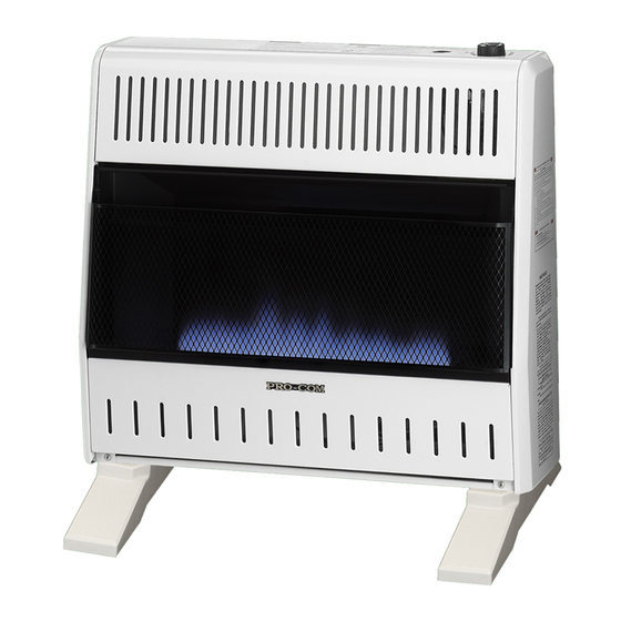
VENT-FREE GAS WALL
HEATER
OWNER'S OPERATION AND
INSTALLATION MANUAL
BLUE FLAME MODELS
MNSD100TBA, MNSD200TBA
MNSD300TBA, MNSD100HBA
MNSD200TBA-BB
MNSD300TBA-BB
PFS
®
US
Advertisement
Table of Contents

Related Manuals for Procom BLUE FLAMEMNSD200TBA


Summary of Contents for Procom BLUE FLAMEMNSD200TBA
- Page 1 VENT-FREE GAS WALL HEATER OWNER’S OPERATION AND INSTALLATION MANUAL BLUE FLAME MODELS MNSD100TBA, MNSD200TBA MNSD300TBA, MNSD100HBA MNSD200TBA-BB MNSD300TBA-BB ® WARNING: If the information in this manual is not followed exactly, a fire or explosion may result causing property damage, personal injury or loss of life. —...
-
Page 2: Table Of Contents
* Aftermarket: Completion of sale, not for purpose of resale, from the manufacturer. PROCOM HEATING, INC. PATENT INFORMATION This product may be covered by one or more of the following United States patents:... -
Page 3: Safety
SAFETY NATURAL AND PROPANE/LP GAS: Natural IMPORTANT: Read this owner’s and Propane/LP gas are odorless. An odor- manual carefully and completely making agent is added to the gas. The odor before trying to assemble, op- helps you detect a gas leak. However, the erate, or service this heater. -
Page 4: Specifications
SAFETY 1. Do not place Propane/LP supply tank(s) 7. Before using furniture polish, wax, carpet inside any structure. Propane/LP supply cleaner, or similar products, turn heater off. tank(s) must be placed outdoors. If heated, the vapors from these products may create a white powder residue within 2. -
Page 5: Qualified Installing Agency
SPECIFICATIONS MODEL MNSD100HBA MNSD200TBA-BB MNSD300TBA-BB BTU (available) 10,000 20,000 30,000 Ignition Electric Piezo Electric Piezo Electric Piezo Gas Type Using Natural Gas Using Natural Gas Using Natural Gas Pressure Regulator Setting 4" W.C. 4" W.C. 4" W.C. Maximum 9" Maximum 9" Maximum 9"... -
Page 6: Local Codes
LOCAL CODES Install and use heater with care. Follow all State of Massachusetts: The installation local codes. In the absence of local codes, must be made by a licensed plumber or use the latest edition of The National Fuel gas fitter in the Commonwealth of Mas- Gas Code, ANSI Z223.1/NFPA 54*. -
Page 7: Water Vapor: A By-Product Of Unvented Room Heaters
WATER VAPOR: A BY-PRODUCT OF UNVENTED ROOM HEATERS Water vapor is a by-product of gas combus- The following steps will help ensure that water tion. An unvented room heater produces ap- vapor does not become a problem. proximately one (1) ounce (30 mL) of water for 1. - Page 8 AIR FOR COMBUSTION AND VENTILATION VENTILATION AIR Ventilation Air From Inside Building Ventilation Air From Outdoors This fresh air would come from an adjoining Provide extra fresh air by using ventilation unconfined space. When ventilating to an grills or ducts. You must provide two perma- adjoining unconfined space, you must provide nent openings: one within 12"...
-
Page 9: Installation
INSTALLATION NOTICE: This heater is intended WARNING: Never install the for use as supplemental heat. heater Use this heater along with your • 10,000 Btu/Hr in a bathroom primary heating system. Do not • over 10,000 Btu/Hr in a bed- install this heater as your pri- room or bathroom (Check local mary heat source. - Page 10 INSTALLATION CHECK GAS TYPE FASTENING HEATER TO WALL Be sure your gas supply is right for your heat- Mounting Bracket er. Otherwise, call dealer where you bought The mounting bracket is located on back panel the heater for proper type heater. of heater (see Figure 5).
- Page 11 INSTALLATION Methods For Attaching Mounting " " Bracket To Wall Min. Use only the last hole on each end of mount- ing bracket to attach bracket to wall. Attach mounting bracket to a wall only in one of two Only Insert Mounting ways: "...
- Page 12 Attaching to Wall Anchor Method Installing Bottom Mounting Bracket For attaching mounting bracket to hollow 1. Install bottom bracket to heater bottom walls (wall areas between studs) or solid walls with two screws. It may be more conve- (concrete or masonry): nient to remove heater from wall bracket to attach.
- Page 13 INSTALLATION INSTALLATION OF BASE STAND (If Equipped) Before installing heater to base, please make sure you have a hardware packet that con- tains the following items: 2 - Base Feet 4 - Sheet Metal Screws 1. Carefully lay heater on its back on a table with the bottom of the heater extending outside the table edge.
- Page 14 INSTALLATION GAS SELECTION This appliance is factory INLET GAS PRESSURE preset for propane/LP gas. MAX 1/2 PSIG (3.5 KPA) No changes are required for connecting to propane/LP. Only a qualified installer or service technician can perform gas selec- tion and connecting to gas supply. Gas Connection CAUTION: Two gas line in- Figure 13 - Back of Heater...
- Page 15 INSTALLATION 2. Apply thread sealant to the threads on Use only the cap supplied on the the connection fitting. While pushing in, regulator. Do not use an off the rotate the fitting clockwise until the threads shelf pipe plug. This can damage engage the regulator.
- Page 16 INSTALLATION CONNECTING TO GAS SUPPLY CAUTION: For natural gas, WARNING: A qualified ser- check your gas line pressure vice technician must connect before connecting heater to gas heater to gas supply. Follow all line. Gas line pressure must be local codes. no greater than 9.5"...
- Page 17 INSTALLATION Apply pipe joint sealant lightly to male threads. the vent pointing down as shown in Figure This will prevent excess sealant from going 16. Pointing the vent down protects it from into pipe. Excess sealant in pipe could result freezing rain or sleet.
- Page 18 INSTALLATION 4. Check all joints of gas supply piping sys- 5. Correct all leaks at once. tem. Apply a noncorrosive leak detection 6. Reconnect heater and equipment shutoff fluid to all joints. If bubbles form, there may valve to gas supply. Check reconnected be a leak.
-
Page 19: Operation
OPERATION FOR YOUR SAFETY READ BEFORE LIGHTING not use any phone in your building. WARNING: If you do not fol- • Immediately call your gas supplier low these instructions exactly, a from a neighbor’s phone. Follow the fire or explosion may result caus- gas supplier’s instructions. - Page 20 OPERATION Note: If pilot goes out, repeat steps 3 CAUTION: Do not try to ad- through 7. This heater has a safety inter- just heating levels by using the lock system. Wait one (1) minute before lighting pilot again. equipment shutoff valve. 8.
- Page 21 OPERATION TO TURN OFF GAS TO APPLIANCE Shutting Off Heater Shutting off burner only (pilot stays lit) 1. Turn control knob clockwise to the OFF position. Turn control knob clockwise to the PILOT/IGN position. 2. Turn off all electric power to the appliance if service is to be performed.
-
Page 22: Electrical Connection
ELECTRICAL CONNECTION FOR HEATERS EQUIPPED WITH A BLOWER Do not use this heater if any part of it has been under water. Immediately call a qualified ser- vice technician to inspect the Cover of fireplace and replace any part Grounded Grounding Pin Outlet Box of the electrical system which... -
Page 23: Inspecting Heater
INSPECTING HEATER IMPORTANT: Owner’s should check pilot flame pattern and burner flame pattern often. Incorrect flame patterns indicate the need for cleaning (see Care and Maintenance, page 24) or service. WARNING: Only a qualified service person should service and repair heater. This includes maintenance requiring replacement or alteration of components. -
Page 24: Care And Maintenance
CARE AND MAINTENANCE WARNING: Turn off heater and let cool before servicing. CAUTION: You must keep control areas, burner, and circulating air passageways of heater clean. Inspect these areas of heater before each use. Have heater inspected yearly by a qualified service techni- cian. -
Page 25: Troubleshooting
TROUBLESHOOTING WARNING: If you smell gas: • Shut off gas supply. • Do not try to light any appliance. • Do not touch any electrical switch; do not use any phone in your building. • Immediately call your gas supplier from a neighbor’s phone. Fol- low the gas supplier’s instructions. - Page 26 TROUBLESHOOTING Problem Possible Cause Corrective Action When ignitor button is 1. Ignitor electrode is posi- 1. Replace pilot assembly. pressed in, there is no tioned wrong. Ignitor elec- spark at ODS/pilot. trode is broken. 2. Ignitor electrode is not con- 2.
- Page 27 TROUBLESHOOTING Problem Possible Cause Corrective Action Burner(s) does not light 1. Burner orifice is clogged. 1. Clean burner orifice (see after ODS/pilot is lit. Care and Maintenance, page 24) or replace burner orifice. 2. Burner orifice diameter is too 2. Replace burner orifice. small.
-
Page 28: Service Hints
You may feel your gas pressure is too low. If so, contact your local gas supplier. TECHNICAL SERVICE You may have further questions about installation, operation, or troubleshooting. If so, contact ProCom Heating, Inc. at 1-866-573-0674. When calling, please have your model and serial numbers of your heater ready. www.usaprocom.com... -
Page 29: Replacement Parts
1-866-573-0674 for referral information. ACCESSORIES Purchase these heater accessories from your local dealer. If they can not supply these acces- sories, contact ProCom Heating, Inc. at 1-866-573-0674 for information. EQUIPMENT SHUTOFF VALVE For all models. Equipment shutoff valve with 1/8” NPT tap. -
Page 30: Parts
PARTS MODELS MNSD100HBA & MNSD100TBA T-Stat Manual www.usaprocom.com 200213-01B... - Page 31 PARTS MODELS MNSD100HBA & MNSD100TBA This list contains replaceable parts for your heater. When ordering replacement parts, follow the instructions listed under Replacement Parts on page 29 of this manual. ITEM MNSD100HBA MNSD100TBA DESCRIPTION Cabinet Assembly Reflector Unit ML087-03 ML087-03 Upper Glass Retainer ML086-03 ML086-03...
- Page 32 PARTS MODELS MNSD200TBA & MNSD300TBA www.usaprocom.com 200213-01B...
- Page 33 PARTS MODELS MNSD200TBA & MNSD300TBA This list contains replaceable parts for your heater. When ordering replacement parts, follow the instructions listed under Replacement Parts on page 29 of this manual. ITEM MNSD200TBA MNSD300TBA DESCRIPTION Cabinet Assembly Reflector Unit ML087-02 ML087-01 Upper Glass Retainer ML086-02 ML086-01...
- Page 34 PARTS MODELS MNSD200TBA-BB & MNSD300TBA-BB www.usaprocom.com 200213-01B...
- Page 35 PARTS MODELS MNSD200TBA-BB & MNSD300TBA-BB This list contains replaceable parts for your heater. When ordering replacement parts, follow the instructions listed under Replacement Parts on page 29 of this manual. ITEM MNSD200TBA-BB MNSD300TBA-BB DESCRIPTION Cabinet Assembly Reflector Unit ML087-02 ML087-01 Upper Glass Retainer ML086-02 ML086-01...
-
Page 36: Warranty
We make no other warranty, expressed or implied. LIMITED WARRANTY ProCom Heating, Inc. warrants this product to be free from defects in materials and components for ONE (1) year from the date of first purchase, provided that the product has been properly installed by a qualified installer in accordance with all local codes and instructions furnished with the unit, operated and main- tained in accordance with all applicable instructions.
Need help?
Do you have a question about the BLUE FLAMEMNSD200TBA and is the answer not in the manual?
Questions and answers