Procom MN060HBA Owner's Operation And Installation Manual
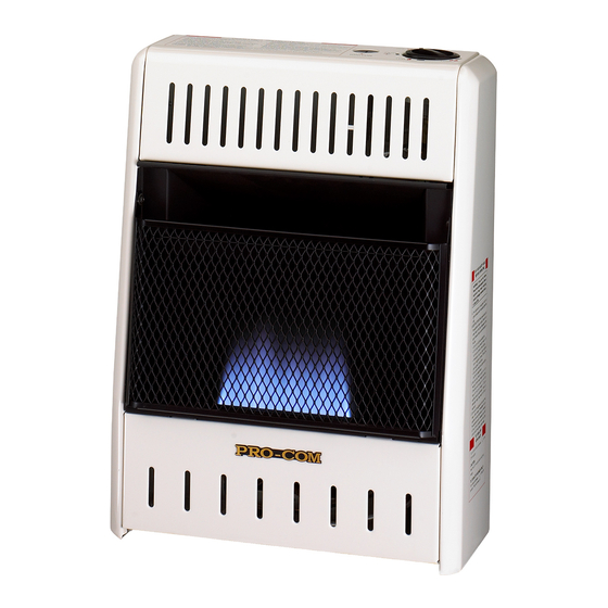
Vent-free natural gas space heater
Hide thumbs
Also See for MN060HBA:
- Owner's operation & installation manual (24 pages) ,
- Owner's operation and installation manual (24 pages)
Table of Contents
Advertisement
WARNING: If the information in this manual is not
followed exactly, a fire or explosion may result causing
property damage, personal injury or loss of life.
— Do not store or use gasoline or other flammable va-
pors and liquids in the vicinity of this or any other
appliance.
— WHAT TO DO IF YOU SMELL GAS
• Do not try to light any appliance.
• Do not touch any electrical switch; do not use any
phone in your building.
• Immediately call your gas supplier from a neighbor's
phone. Follow the gas supplier's instructions.
• If you cannot reach your gas supplier, call the fire
department.
— Installation and service must be performed by a quali-
fied installer, service agency or the gas supplier.
INSTALLER: Leave this manual with the appliance.
CONSUMER: Retain this manual for future reference.
Questions, problems, missing parts? Before returning to your retailer, call
our customer service department at 1-866-573-0674, 8:00 am - 4:30 pm CST,
Monday through Friday or email customerservice@usaprocom.com
VENT-FREE NATURAL GAS
SPACE HEATER
OWNER'S OPERATION AND
INSTALLATION MANUAL
INFRARED MODELS
MN060HBA, MN100HBA
MN100TBA
Advertisement
Table of Contents

Related Manuals for Procom MN060HBA


Summary of Contents for Procom MN060HBA
- Page 1 VENT-FREE NATURAL GAS SPACE HEATER OWNER’S OPERATION AND INSTALLATION MANUAL INFRARED MODELS MN060HBA, MN100HBA MN100TBA WARNING: If the information in this manual is not followed exactly, a fire or explosion may result causing property damage, personal injury or loss of life.
-
Page 2: Table Of Contents
TABLE OF CONTENTS Safety ............3 Operation ..........16 Specifications ..........4 Inspecting Heater ........19 Preparing For Installation ......5 Care And Maintenance ......20 Qualified Installing Agency ......5 Troubleshooting ........21 Product Features ........5 Parts ............24 Local Codes.......... -
Page 3: Safety
SAFETY IMPORTANT: Read this owner’s WARNING: Any change to manual carefully and completely this heater or its controls can before trying to assemble, op- be dangerous. erate, or service this heater. Improper use of this heater can WARNING: Do not use any cause serious injury or death accessories not approved for from burns, fire, explosion,... -
Page 4: Specifications
SAFETY 1. Model MN060HBA shall not be installed 5. Do not run heater: in a bedroom. Models MN100HBA and • Where flammable liquids or vapors are MN100TBA shall not be installed in a used or stored. bedroom or bathroom. • Under dusty conditions. -
Page 5: Preparing For Installation
PREPARING FOR INSTALLATION Before beginning assembly or operation of the Ignitor Button product, make sure all parts are present. Com- Control Knob pare parts with package contents list. If any part is missing or damaged, do not attempt to assemble, install or operate the product. Con- tact customer service for replacement parts. -
Page 6: Local Codes
LOCAL CODES Install and use heater with care. Follow all State of Massachusetts: The installation local codes. In the absence of local codes, must be made by a licensed plumber or use the latest edition of The National Fuel gas fitter in the Commonwealth of Mas- Gas Code, ANSI Z223.1/NFPA 54*. -
Page 7: Air For Combustion And Ventilation
AIR FOR COMBUSTION AND VENTILATION heat loss in homes. Home owners weather WARNING: This heater shall strip and caulk around windows and doors not be installed in a confined space to keep the cold air out and the warm air in. During heating months, home owners want or unusually tight construction their homes as airtight as possible. - Page 8 AIR FOR COMBUSTION AND VENTILATION DETERMINING FRESH-AIR FLOW FOR HEATER LOCATION Determining if You Have a Confined or Unconfined Space Use this work sheet to determine if you have Example: a confined or unconfined space. Gas water heater __________ Btu/Hr 30,000 Vent-free heater + _________ Btu/Hr...
-
Page 9: Ventilation Air
AIR FOR COMBUSTION AND VENTILATION WARNING: If the area in which the heater may be operated is smaller than that defined as an unconfined space or if the building is of unusually tight construction, provide adequate combustion and ventilation air by one of the methods described in the National Fuel Gas Code, ANSI Z223.1/NFPA 54, the International Fuel Gas Code, or applicable local codes. -
Page 10: Installation
WARNING: Never install the See Air for Combustion and Ventilation, pages heater 7 through 9. • Model MN060HBA in a bed- CHECK GAS TYPE room Be sure your gas supply is right for your heat- • Models MN100HBA or er. -
Page 11: Fastening Heater To Wall
INSTALLATION 2. Take out the bulb clip from the hardware CEILING package and insert it into the square hole. Insert the sensing bulb into the bulb clip 36" (see Figure 5). Minimum 6" FASTENING HEATER TO WALL Minimum From Mounting Bracket Sides of The mounting bracket is located on back panel Heater... - Page 12 INSTALLATION Methods For Attaching Mounting Attaching Mounting Bracket To Wall Bracket To Wall Note: Wall anchors, mounting screws, and Use only the last hole on each end of mount- spacers are in hardware package. The hard- ing bracket to attach bracket to wall. Attach ware package is provided with heater.
-
Page 13: Connecting To Gas Supply
INSTALLATION Placing Heater On Mounting 6. Replace heater onto mounting bracket. Bracket 7. Place spacers between bottom mounting 1. Locate two horizontal slots on back panel holes and wall anchor or drilled hole. of heater (see Figure 11). 8. Hold spacer in place with one hand. With 2. - Page 14 INSTALLATION CAUTION: Use only new, CAUTION: Use pipe joint black iron or steel pipe. Inter- sealant that is resistant to gas. nally tinned copper tubing may Before installing heater, make sure you have be used in certain areas. Check the items listed below: your local codes.
-
Page 15: Checking Gas Connections
INSTALLATION Typical Inlet Pipe Diameters Apply pipe joint sealant lightly to male threads. Models up to 20,000 BTU/hr use 3/8" black This will prevent excess sealant from going iron pipe or greater. Models 25,000 BTU/hr into pipe. Excess sealant in pipe could result and higher use 1/2"... -
Page 16: Operation
INSTALLATION PRESSURE TESTING HEATER GAS CONNECTIONS 1. Open equipment shutoff valve (see Fig- fluid to all joints. Bubbles forming show a ure 14, page 15). leak. 2. Open main gas valve located on or near 5. Correct all leaks at once. gas meter. - Page 17 OPERATION Note: If pilot goes out, repeat steps 3 Model MN060HBA through 7. This heater has a safety inter- lock system. Wait one (1) minute before HIGH PILOT/IGN lighting pilot again. 8. To select the desired heating level, partially press down the control knob slightly and turn counterclockwise .
-
Page 18: Thermostat Control Operation
OPERATION Note: If pilot does not stay lit, refer to 8. Turn control knob counterclockwise Troubleshooting, pages 22 though 24. to desired heating level. The main burner Also contact a qualified service technician should light. Set control knob to any heat or gas supplier for repairs. -
Page 19: Inspecting Heater
INSPECTING HEATER IMPORTANT: Owner’s should check pilot flame pattern and burner flame pattern often. Incorrect flame patterns indicate the need for cleaning (see Care and Maintenance, page 20) or service. WARNING: Only a qualified service person should service and repair heater. This includes maintenance requiring replacement or alteration of components. -
Page 20: Care And Maintenance
CARE AND MAINTENANCE WARNING: Turn off heater and let cool before servicing. CAUTION: You must keep control areas, burner, and circulating air passageways of heater clean. Inspect these areas of heater before each use. Have heater inspected yearly by a qualified service techni- cian. -
Page 21: Troubleshooting
TROUBLESHOOTING WARNING: If you smell gas: • Shut off gas supply. • Do not try to light any appliance. • Do not touch any electrical switch; do not use any phone in your building. • Immediately call your gas supplier from a neighbor’s phone. Fol- low the gas supplier’s instructions. - Page 22 TROUBLESHOOTING Problem Possible Cause Corrective Action ODS/pilot lights but flame 1. Control knob is not fully 1. Press in control knob fully. goes out when control pressed in. knob is released. 2. Control knob is not pressed 2. After ODS/pilot lights, keep in long enough.
- Page 23 TROUBLESHOOTING Problem Possible Cause Corrective Action Heater produces a whis- 1. Turning control knob to high 1. Turn control knob to low tling noise when burner position when burner is cold. position and let warm up for is lit. a minute. 2.
-
Page 24: Parts
PARTS MODEL MN060HBA www.usaprocom.com 200044-01A... - Page 25 PARTS MODEL MN060HBA This list contains replaceable parts for your heater. When ordering replacement parts, follow the instructions listed under Replacement Parts on page 25 of this manual. ITEM PART # DESCRIPTION MB10008 Cabinet Assembly MB09003 Lower Front Panel MB11005...
- Page 26 PARTS MODEL MN100HBA ODS/Pilot Assembly www.usaprocom.com 200044-01A...
- Page 27 PARTS MODEL MN100HBA This list contains replaceable parts for your heater. When ordering replacement parts, follow the instructions listed under Replacement Parts on page 25 of this manual. ITEM PART # DESCRIPTION MB10008 Cabinet Assembly MB09003 Lower Front Panel MB11005 Reflector Unit ML086-03 Glass...
- Page 28 PARTS MODEL MN100TBA ODS/Pilot Assembly www.usaprocom.com 200044-01A...
- Page 29 PARTS MODEL MN100TBA This list contains replaceable parts for your heater. When ordering replacement parts, follow the instructions listed under Replacement Parts on page 25 of this manual. ITEM PART # DESCRIPTION MB10007 Cabinet Assembly MB09003 Lower Front Panel MB11005 Reflector Unit ML086-03 Glass...
-
Page 30: Replacement Parts
• Purchase date ACCESSORIES Purchase these heater accessories from your local dealer. If they can not supply these acces- sories, contact ProCom Heating, Inc. at 1-866-573-6074 for information. EQUIPMENT SHUTOFF VALVE For all models. Equipment shutoff valve with 1/8" NPT tap. -
Page 31: Service Hints
TECHNICAL SERVICE You may have further questions about installation, operation, or troubleshooting. If so, contact ProCom Heating, Inc. at 1-866-573-6074. When calling, please have your model and serial numbers of your heater ready. www.usaprocom.com... -
Page 32: Warranty
We make no other warranty, expressed or implied. LIMITED WARRANTY ProCom Heating, Inc. warrants this product to be free from defects in materials and components for ONE (1) year from the date of first purchase, provided that the product has been properly installed by a qualified installer in accordance with all local codes and instructions furnished with the unit, operated and main- tained in accordance with all applicable instructions.
Need help?
Do you have a question about the MN060HBA and is the answer not in the manual?
Questions and answers