Table of Contents
Advertisement
CONTENTS
1.
Warnings and operation notes..........................................3
2.
Unpacking....................................................................5
3.
Installation.....................................................................6
4.
5.
Advanced Camera Setup..................................................19
6.
Specifications.................................................................36
Before attempting to connect or operate this product, read these instructions carefully.
Save this manual for future use.
Ax40W2/4/8-series
User Guide
Advertisement
Table of Contents

Related Manuals for i3 International Ax40W2 series


Summary of Contents for i3 International Ax40W2 series
-
Page 1: Table Of Contents
Ax40W2/4/8-series User Guide CONTENTS Warnings and operation notes..........3 Unpacking..............5 Installation..............6 Connecting your IP Camera to the SRX-Pro Server..11 Advanced Camera Setup..........19 Specifications..............36 Before attempting to connect or operate this product, read these instructions carefully. Save this manual for future use. -
Page 2: I3-Trng-Cams-Ax40W.indd
Neither i3 International Inc. nor its dealers or distributors shall be liable to any person or entity with respect to any liability, loss, or damage, caused or alleged to have been caused directly or indirectly by this information. -
Page 3: Warnings And Operation Notes
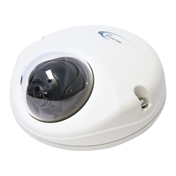
Thank you for purchasing an i3 Ax40W-series Mini-dome (Wedge) Fixed camera. If the system needs to be modified or repaired, contact a certified i3 International Dealer/Installer. When serviced by unauthorized technician, the system warranty will be voided. Should you have any problems or questions regarding our products, contact your local i3 International Dealer/Installer. -
Page 4: Power Supply
1.2 Power Supply When using 12VDC, ensure the supplied voltage meets the power consumption requirements of this camera before powering the camera on. Incorrect voltage may cause irreparable damage to the video camera and will effectively void the camera warranty. The camera also comes with the built-in PoE power support. WARNING! DO NOT connect both PoE and DC12V power connectors at the same time. -
Page 5: Unpacking
2. Unpacking Check that the items received match those listed on the order form and packing slip. In addition to this manual and a fully assembled camera, the dome camera packing box includes: 1. User Manual CD x1 2. Guide Pattern sticker x1 3. -
Page 6: Installation
3. Installation Use the appropriate brackets and equipment to mount the camera. After installing the camera, your network camera should be accessed from your local network. Camera Parts RESET DEFAULT Camera Dome VIDEO OUT Camera Body - Top View Camera Body - Side View VIDEO OUT: Video output connector. - Page 7 Power Connectors Connect the PoE or DC12V power connector. PoE (IEEE 802.3af): Connect the RJ-45 connector to a PoE compatible network device that supplied power through the Ethernet cable. DC12V: Connect the DC12V power connector to a DC12V power. WARNING! DO NOT connect both PoE and DC12V power connectors at the same time.
- Page 8 3.3 Disassembling the Camera Before you mount and adjust the camera, follow these steps to disassemble the camera. 1. Using the hex key provided, loosen two screws on the cover. 2. Remove the dome cover. 3.4 Attaching the Desiccant 1. Take the desiccant out of the package (#11 on Accessories list on page 5) 2.
-
Page 9: Mounting The Camera
3.5 Mounting the Camera Depending on mounting surface, you can use a combination of Plastic Anchors and Tapping Screws or Machine Type Screws, Wing nuts and Washers. 1. Prepare the mounting surface. Adhere the Mounting Template (#2 on Accessories list on page 5) to the surface. 2. - Page 10 3.6 Adjusting the Camera Position 1. Loosen two screws, as shown in the picture below. 2. Adjust the lens to the desired shooting angle until the required view is achieved 3. Re-tighten the screws once the desired view is achieved. Loosen two screws before adjusting the lens 3.7 Completing the Installation...
-
Page 11: Connecting Your Ip Camera To The Srx-Pro Server
4. Connecting your IP Camera to the SRX-Pro Server 4.1 Camera Connection Options Connection Type 1: Crossover direct connection i3 SRX-Pro Server Connection Type 2: Via Gigabit Switch i3 SRX-Pro Server 4.2 Hardware/Software Requirements The following requirements must be met to achieve a successful network connection with the Ax40W-series IP camera. - Page 12 Switch A Gigabit Switch is required to monitor two or more cameras from the same SRX-Pro Server. 4.3 Configuring Internet Explorer for Video Display Your Internet Explorer (v.8.0 or higher) must first be configured in order to properly display video stream from your Annexxus camera. Follow these instructions to configure your Internet Explorer browser.
- Page 13 4.4 Using Annexxus Finder to assign IP Address to your IP Camera Camera’s default IP address is 192.0.0.16 Camera’s default subnet mask address is 255.255.255.0. Default camera User Name and Password: FW ver. i3_00_026-40 | User name: admin / Password: 1234 FW ver.
- Page 14 9. Next, select desired camera in the Annexxus Finder software by double-clicking it in the list and click Edit. 10. Enter the new IP address and Subnet Mask of the camera in the Change IP Address area. The new camera IP address must match the original range of your SRX-Pro LAN or NIC1 card.
- Page 15 12. Wait a few moments as the new IP address is being applied to your Annexxus camera. Wait for the following message to be displayed. Click OK to close it. 13. Repeat Steps 1-12 for all detected Annexxus cameras in the Annexxus Finder. 14.
- Page 16 17. Annexxus camera interface will be displayed in the Internet Explorer window. You should be able to see the camera image on the screen. If you do not see the camera image on the screen, call i3 International tech support for help.
- Page 17 1. Log In and go to the Setup -> IP Camera tab. 2. Click the Search button to display connected Annexxus cameras. i3-TRNG-CAMS-Ax40W.indd Rev. 141126...
- Page 18 1. Select the detected camera in the list and click Select. 2. In the Select IP Camera window, enter the default camera User Name and the default Password, then click Add. Default Login/Password: FW ver. i3_00_026-40 | User name: admin / Password: 1234 FW ver.
-
Page 19: Advanced Camera Setup
5. Advanced Camera Setup To access Annexxus camera’s advanced setup, go to Setup -> IP Camera tab, select the camera in the list of added IP cameras and click the Advanced Setup button. The password window should be displayed. Enter the default camera User Name and the default Password. - Page 20 In the main interface, you may adjust your camera’s Brightness, Contrast, Saturation and Sharpness levels. Click Save to save adjusted settings or Default to set all settings back to 50%. Note: This panel is enabled in the Live View mode only and is disabled when in the Setup mode.
-
Page 21: Camera Settings
Camera Settings: • Camera Name: The name of the camera will be displayed at the top of the Internet browser page. • Video Codec: Set the compression mode to MJPEG or H264 • Resolution: Set the resolution of the recorded video to D1 (720x480), SVGA (800x600), or 720P (1280x720). - Page 22 5.2 Video Setup Switch to the Advanced Setup by clicking the Advance Setup button on the bottom left-hand corner of the screen as shown on the previous page. The Setup screen will change to reveal multiple setup tabs. Video Setup tab is displayed by default.
- Page 23 Note: Enabling Streams 2 and 3 may cause frames being dropped on Stream 1. Configure Stream 1 - Primary Streaming (Recorded Video): • Video Codec: Set the compression mode to H264 or MJPEG • Resolution: Set the resolution of the recorded video to one of the following: »...
- Page 24 • Video Codec: Set the compression mode to H264 or MJPEG • Resolution: Set the resolution of the recorded video to one of the following: » “None” to disable Third Streaming » CIF (352 x 240) » VGA (640 x 480) »...
- Page 25 5.3 Alarm/Motion (optional) • Motion Detection: Enable or Disable Motion Detection • Sensitivity: When Enabled, set the Motion Sensitivity to HIGH, MEDIUM, LOW • Set Motion. Wait for the static image, then click Set Motion button. Any change to the current static image will be recognized as motion. 5.4 Privacy Zone (optional) In the Privacy Zone setup tab, select an area that needs to be blocked off with a rectangle on Live View and from video recording because of privacy or other...
- Page 26 To draw the privacy zone, follow these instructions: 1. Set the Privacy Zone Enable to ON to activate a privacy zone. 2. Position your mouse cursor over the Preview window, press and hold the left mouse button. 3. While holding down the left mouse button, drag the cursor to draw a rectangular area over the zone that needs to be concealed.
- Page 27 Auto Exposure: Select this option to correct the exposure automatically. • Exposure Mode: is set to AES • Slow Shutter: Set the shutter speed. Acceptable value range is from 1/30 to 1/3.75 sec. Select OFF to disable the feature. • Max Gain: Set the maximum gain value.
-
Page 28: Smtp Server
5.6 Network Recording Under Network Recording tab, the camera can be configured to send out an email alert every time motion is detected. It can also record video to a configured FTP server based on motion or on pre-set schedule. Note: Only MJPEG video streams can be used with SMTP &... - Page 29 Condition Settings for Sending E-mail by Motion: • Subject: Enter the email subject • Message: Enter the body of the email message • Attach Image: Set to ON to attach a snapshot to the motion-triggered email Email Address List: • Configure up to three separate email reciepients.
- Page 30 Motion Recording Settings: • Motion Recording Cycle: Set the video recording length (in sec) preceeding the triggered motion. Values range between 1 and 30 seconds. • Pre Recording Frame: Set the video frame rate for the video preceeding the triggered motion. Values range between 1 and 10 frames per second. •...
-
Page 31: Osd Settings
Network settings: • DHCP: Enable or Disable to have the network automatically assign an IP address to the camera. • IP Address: Manually enter the camera’s IP address here. This option should NOT be used if DHCP is enabled. • Subnet Mask: Manually enter the camera’s Subnet Mask here. -
Page 32: User Management
5.8 User Management User Management tab displays the list of users that have access to the Annexxus camera. The username and password from this setup tab are used when connecting the camera to SRX-Pro Server. Reminder: Whenever a change is made to the Annexxus camera user in the camera’s Advanced Setup ->... -
Page 33: System Setup
All Annexxus-series cameras are sold with the most recent version of the firmware already installed. If in the future firmware updates are released, you can update your camera’s firmware by first downloading the firmware file from i3 International’s website or FTP site. After downloading firmware file, click the Browse... button in the camera’s System setup tab and locate the new firmware file. - Page 34 Restart/Reset: • Click Restart Camera to restart your Annexxus-series camera. This will cause a temporary disconnect, no video will be recorded while the camera is restarting but all custom settings will be saved. Camera restart is required after the firmware update. After clicking, a pop up will appear asking you to confirm. Click Yes.
- Page 35 5.10 Logs Logs setup tab displays all login and Alarms log records. i3-TRNG-CAMS-Ax40W.indd Rev. 141126...
-
Page 36: Specifications
i3-TRNG-CAMS-Ax40W.indd Rev. 141126... - Page 37 i3-TRNG-CAMS-Ax40W.indd Rev. 141126...
-
Page 38: Birchmount Road, Unit
INTERNATIONAL INC. 1.866.840.0004 U.S.A. 1967 Wehrle Drive, Canada 780 Birchmount Road, www.i3international.com Suite 1, PMB# 034 Buffalo Unit 16, Scarborough, NY, 14221 ON, M1K 5H4...
Need help?
Do you have a question about the Ax40W2 series and is the answer not in the manual?
Questions and answers