Advertisement
Quick Links
CONTENTS
SAFETY INFORMATION... ..................................................
Product Overview .............................................................
SPECIFICATION..................................................................
INSTALLATION................................................................
Before attempting to connect or operate this product, please read these
instructions carefully and save this manual for future use.
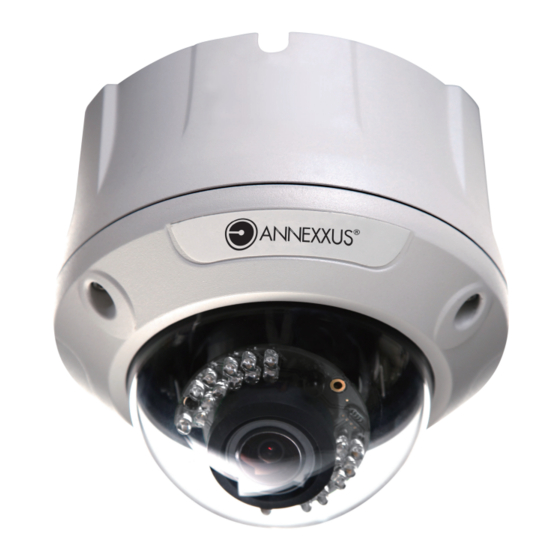
Ax41V1MVR Megapixel
Dome Camera
Instruction Manual
1
3
6
8
Advertisement

Subscribe to Our Youtube Channel
Related Manuals for i3 International ANNEXXUS Ax41V1MVR


Summary of Contents for i3 International ANNEXXUS Ax41V1MVR
- Page 1 Ax41V1MVR Megapixel Dome Camera Instruction Manual CONTENTS SAFETY INFORMATION............. Product Overview ............. SPECIFICATION..............INSTALLATION..............Before attempting to connect or operate this product, please read these instructions carefully and save this manual for future use.
- Page 2 AX41V1MVR 1.1 Precautions When installing your Annexxus system, be sure to avoid: excessive heat, such as direct sunlight or heating appliances moisture, dust, and smoke strong magnetic fields close to sources of powerful electromagnetic radiation, such as radios or TV transmitters ...
- Page 3 Product Overview Key Features Exceptional Images This camera employs a 5MP CMOS sensor that quadruples sensitivity without blurring. The camera’s technology provides picture with greater detail in even the most difficult lighting conditions. It delivers crisp images that are perfect for object- and person-recognition. Smart focus A built-in nine-point focus indicator enables the camera to focus precisely and automatically on objects, relieving users of the need to adjust the focus manually.
- Page 4 2.0 Camera Parts and Definition 1. Power In (Red+/Black-): power connector, DC12V/AC24V 2. RJ-45 Ethernet Connector: network connection. Support PoE (Power over Ethernet) 3. BNC: video output 4. Audio Out (Green): audio output 5. Audio In (Red): audio input 6. Alarm Out (Orange): alarm signal output port RS485+(Green): function reserved RS485- (Yellow): function reserved 7.
- Page 5 2.1 Specification Specification Image System Image sensor 1/2.5" 5 MP CMOS image sensor optimized for low-light performance Effective pixels 2592 (H) X 1944 (V) Image Compression Triple Streaming : MPEG4 x2/ Motion JPEG x1 Method Resolution/ Frame Rate MPEG4: HD 720P 1280 X 720 @30fps, 640 X480@30fps, 352 X192@30fps MJPEG: 640 X 480@30fps, 640 X 352@30fps Electric Sync system...
- Page 6 I/O connector Video port BNC X1, 1.0Vp-p, 75Ω Alarm port Terminal block Audio port 3.5mm Phone Jack Mechanism Dimensions(øxH) ø158mmx144mm (ø6.22" x 5.67") Weight 1.28 kg (2.82 lb.) Protection Class IP66/IP67, vandal-proof: 1000 kg impact resistance Option Without Heater With Heather One year parts and labour Warranty 3.
- Page 7 3. Install the camera onto the ceiling/wall and fasten securely using the screws provided. Use the screws to security fasten! Rotate the main bracket 4. Adjust the pan/tilt angle: rotate the main bracket (or the pan adjustment) adjust the pan angle and rotate the pan adjustment to adjust the tilt angle.
- Page 8 Zoom lever 5. Adjust focus lever: loosen the focus lever counterclockwise and adjust the focus for optimum picture sharpness. Focus lever...
- Page 9 6. Install the dome cover: place the dome cover to match the screw positions and then tighten 3 screws to lock it securely using the allen (hex) key provided. 3.1.5 Using “Smart Focus” to Adjust Focus Smartly This network box camera provides “Smart Focus” to obtain correct focus on a subject, instead of requiring users to adjust focus manually.
- Page 10 3.2 Network Camera Diagram Connection type: 1 Crossover direct connection i³ iP-Pro Server Connection type: 2 VIA a Gigabit Switch i³ iP-Pro Server 3.3 Hardware/Software Requirement Computer i³ SRX-Pro/iP-Pro Version 1.610 or higher Windows Vista or XP as OS ...
- Page 11 3. Check that the camera and computer are connected by pinging the IP address you have set. To do this, start a command prompt and type the IP address you set. If the message “Reply from…” appears, it means the connection is done. 4.
- Page 12 Press OK to save the settings. Close all Internet Explorer Windows and start a new window. This will allow the new settings to take effect. 7. Type your set IP address into the browser. 8. Then you should be able to see the camera image screen as follows: 3.5 Using “Annexxus Finder”...
- Page 13 1. Insert the CD in the CD-ROM drive. 2. Double click “AnnexxusFinder.exer” to run the program. Follow the instructions to install. 3. After successfully installing “Annexxus Finder”, double click the “Annexxus Finder” icon which is displayed in your desktop. An “Annexxus Finder” window will pop out. The window will display a list of net cameras which you are using currently.
- Page 14 4. Live View Live view is designed for general users to control the camera. " Video Format", “Snapshot”, “Recording LED”, “Live” and “Setup” functions are listed on the live view. Please note, only administrators can access “Setup” to configure camera settings. 4.1 Video Format Select a resolution type for live view.
- Page 15 Setup Button Click on “Setup” to configure camera settings. 5.1 Image Settings...
- Page 16 “Image” is used to change any picture setting on the camera. Remember to click “Save” to keep your settings. 5.1.1 Image Basic Setting Every parameter of “Basic Setting” affects the displayed image. Specify appropriate parameters in the following section. Camera Name: enter a desired network camera name.
- Page 17 Advance Setting Advance or Basic Button TV System: "NTSC" and "PAL" are provided for different TV system settings. Mirror: set images as left or right. Select ON or OFF to enable or disable this function. Flip: set images upside down. Select ON or OFF to enable or disable this function. -MJPEG Setting ...
- Page 18 “White Balance”, “Day and Night”, “AES”, “Lumii”, “Working Environment”, “Lens Format”, “BLC”, “Brightness”, “Contrast”, “Saturation” and “Sharpness” are provided for you to set the quality of images. Please click the “Save” button to save your image settings. -Advanced settings White Balance: select a white balance mode according to external lighting condition for the best color temperature.
- Page 19 Anti-Flicker: reduce color rolling for indoor environment. Lens Format: choose an appropriate lens matching with the lens size which you have installed. BLC (Backlight Compensation): this function adjusts the image to compensate for areas that are too dark due to insufficient light. ...
- Page 20 NTP Server Setting 9. NTP Server: assign an IP address or domain name for a time server. 10. Time Zone: select a correct time zone. 5.3 System...
- Page 21 In this section, you can configure the system settings, including “Time Stamp”, “Current Date & Time” and “New Date & Time”. Current Time Display the current time on the camera. Date and time will be changed after you configure it in the “New Time”...
- Page 22 Factory Default – Resets the camera to factory settings but keeps the Network settings. After clicking, a pop up will appear asking you to confirm. Click Yes. Hard factory default – Resets the camera to factory settings and will cause all parameters (including the IP address) to be reset.
- Page 23 It displays all login and alarm records. 5.4.3 Alarm You can set to trigger alarms on the conditions that an event or action signal has been sent to the camera. Trigger an Alarm When Ethernet is Lost: set an alarm condition when Ethernet disconnected. ...
- Page 24 Press “Save” to save your settings. Action: Configure image transfer settings after triggering an alarm. Digital Output: select “OFF” to disable this function or “ON” to enable this function. If select “ON”, choose an output file’s resolution as “Low” or “High”. Digital Output - If you want to set digital output function start, you need to set ON.
Need help?
Do you have a question about the ANNEXXUS Ax41V1MVR and is the answer not in the manual?
Questions and answers