Table of Contents
Advertisement
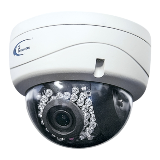
Ax46/66-series
User Guide
CONTENTS
1. Warnings and operation notes.................................3
2. Unpacking..................................................................5
3. Installation................................................................6
4. Connecting to the SRX-Pro Server.........................10
5. Advanced Camera Setup.........................................18
6. Specifications..........................................................36
Before attempting to connect or operate this product, read these instructions carefully.
Save this manual for future use.
Advertisement
Table of Contents

Subscribe to Our Youtube Channel
Related Manuals for i3 International Ax46-series


Summary of Contents for i3 International Ax46-series
-
Page 1: Table Of Contents
Ax46/66-series User Guide CONTENTS 1. Warnings and operation notes.........3 2. Unpacking..............5 3. Installation..............6 4. Connecting to the SRX-Pro Server......10 5. Advanced Camera Setup.........18 6. Specifications............36 Before attempting to connect or operate this product, read these instructions carefully. Save this manual for future use. -
Page 2: I3-Trng-Cams-Ax46/66.Indd
Neither i3 International Inc. nor its dealers or distributors shall be liable to any person or entity with respect to any liability, loss, or damage, caused or alleged to have been caused directly or indirectly by this information. -
Page 3: Warnings And Operation Notes
Thank you for purchasing an i3 Ax46/66-series IR Outdoor Dome Camera. If the system needs to be modified or repaired, contact a certified i3 International Dealer/Installer. When serviced by unauthorized technician, the system warranty will be voided. Should you have any problems or questions regarding our products, contact your local i3 International Dealer/Installer. -
Page 4: Power Supply
1.2 Power Supply When using 12VDC, ensure the supplied voltage meets the power consumption requirements of this camera before powering the camera on. Incorrect voltage may cause irreparable damage to the video camera and will effectively void the camera warranty. The camera also comes with the built-in PoE power support. WARNING! DO NOT connect both PoE and DC12V power connectors at the same time. -
Page 5: Unpacking
2. Unpacking Check that the items received match those listed on the order form and packing slip. In addition to this manual and a fully assembled camera, the dome camera packing box includes: 1. User Manual and Annexxus Finder CD x1 2. -
Page 6: Installation
3. Installation Use the appropriate brackets and equipment to mount the camera. After installing the camera, your network camera should be accessed from your local network. Camera Parts and definitions Mounting base Horizontal stand Infrared lamp plate Lens Vertical stand Cables Black liner Lower dome... - Page 7 3.3 Mounting and adjusting camera This is a dual axis camera and thus a ceiling mounting instead of a wall mounting is recommended in order to provide the camera with an optimal view. When installing on a wall, choose a location and field of view that is straight in front of the camera as much as possible.
- Page 8 2. Disassemble camera prior to mounting. Loosen the set screws on the camera with the supplied hex key to remove the lower dome. 3. Attach the camera to the surface. Fix the mounting base on the surface with the supplied screws. Fig 3-5 - Attaching camera to wall 4.
- Page 9 Fig 3-7 - Reattach dome i3-TRNG-CAMS-Ax46/66.indd Rev. 130816...
-
Page 10: Connecting To The Srx-Pro Server
4. Connecting to the SRX-Pro Server 4.1 Camera Connection Options Connection Type 1: Crossover direct connection i3 SRX-Pro Server Connection Type 2: Via Gigabit Switch i3 SRX-Pro Server 4.2 Hardware/Software Requirements The following requirements must be met to achieve a successful network connection with the Ax46/66-series IP camera. - Page 11 NOT covered by the camera warranty. Switch A Gigabit Switch is required to monitor two or more cameras from the same SRX-Pro Server. 4.3 Configuring Internet Explorer for Video Display Your Internet Explorer (v.8.0 or higher) must first be configured in order to properly display video stream from your Annexxus camera.
- Page 12 4.4 Using Annexxus Finder to assign IP Address to your IP Camera To connect your Annexxus camera to your SRX-Pro Server, follow these instructions: 1. Close SRX-Pro Server software by pressing Alt+Shift+Ctrl+F4. 2. Change the IP address on the onboard NIC (LAN) (or on NIC1 if your SRX-Pro Server has two onboard NIC cards) of your SRX-Pro Server to 192.0.0.XXX to match the default IP range of your Annexxus IP camera.
- Page 13 Remember: Annexxus Cameras cannot share an IP address, each camera requires its own unique IP address. 11. Enter the default camera password: 1234 in the Input Password field and click Save. 12. Wait a few moments as the new IP address is being applied to your Annexxus i3-TRNG-CAMS-Ax46/66.indd Rev.
- Page 14 camera. Wait for the following message to be displayed. Click OK to close it. 13. Repeat Steps 1-12 for all detected Annexxus cameras in the Annexxus Finder. 14. Now that the new IP address has been successfully assigned to your camera, make sure you can connect to it through the Internet Explorer: 15.
- Page 15 1. The Annexxus camera interface will be displayed in the Internet Explorer window. You should be able to see the camera image on the screen. If you do not see the camera image on the screen, call i3 International tech support for help.
- Page 16 1. Log In and go to the Setup -> IP Camera tab. 2. Click the Search button to display connected Annexxus cameras. i3-TRNG-CAMS-Ax46/66.indd Rev. 130816...
- Page 17 1. Select the detected camera in the list and click Select. 2. In the Select IP Camera window, enter the default camera User Name: admin and default Password: 1234, then click Add. 3. The selected camera will be added to the IP Camera list. Don’t forget to assign the IP camera to the SRX-Pro video channel in the Your Annexxus camera is now connected to SRX-Pro Server and is ready to record.
-
Page 18: Advanced Camera Setup
5. Advanced Camera Setup To access Annexxus camera’s advanced setup, go to Setup -> IP Camera tab, select the camera in the list of added IP cameras and click the Advanced Setup button. The password window should be displayed. Enter the default camera User Name: admin and default Password: 1234. - Page 19 In the main interface, you may adjust your camera’s Brightness, Contrast, Saturation and Sharpness levels. Click Save to save adjusted settings or Default to set all settings back to 50%. Note: This panel is enabled in the Live View mode only and is disabled when in the Setup mode.
-
Page 20: Camera Settings
Camera Settings: • Camera Name: The name of the camera will be displayed at the top of the Internet browser page. • Video Codec: The main stream will be in H264. • Resolution: Set the resolution of the recorded video to 640x480, 704x480, 1280x720, or 1280x960 (Ax46) or 1270x720, 1920x1080, or 2048x1536 (Ax66). -
Page 21: Video Adjustment
5.2 Video Setup Switch to the Advanced Setup by clicking the Advance Setup button on the bottom left-hand corner of the screen as shown on the previous page. The Setup screen will change to reveal multiple setup tabs. Video Setup tab is displayed by default. - Page 22 Streaming is the default stream used for video recording and Sub Streaming is used for Live Viewing. Each stream can be configured separately. See Camera Settings in Basic Setup for details about video settings for both streams. Configure Sub Stream (Live View): •...
-
Page 23: Motion Settings
• Digital Noise Reduction: Choose either Close or Normal Mode. After making any setting adjustments, remember to click the Save button to save any changes made. 5.3 Motion (optional) Set motion detection areas for alarms and recording. This setting is best used on cameras placed in an indoor setting with stable lighting conditions. - Page 24 minutes, respectively. Linkage Method: • Send Email: Check to send any motion-recorded image to an email. Configure settings for this option in Network Recording. • Upload to FTP: Check to send any motion-recorded image to an FTP server. Configure settings for this option in Network Recording. Upload FTP Picture Settings: If Upload to FTP is checked, configure these options.
- Page 25 5.4 Tamper Proof (optional) The camera features a tamper-proofing securtiy measure which triggers an alarm whenever areas of the lens are covered. Arming Schedule Settings: • Arming Schedule: Check the checkboxes next to the day to enable motion recording on that day of the week. Linkage Method: •...
- Page 26 6. Click the Stop Drawing button to finish. 7. Set the sensitivity of the tamper-proof area. Select Low, Medium or High Click Clear All to delete all the tamper proof areas. After making any setting adjustments, remember to click the Save button to save any changes made.
-
Page 27: Text Overlay
7. Repeat Steps 1-6 for additional Privacy Zones, if applicable. Click Clear All to delete all the privacy zones. After making any setting adjustments, remember to click the Save button to save any changes made. 5.6 Text Overlay The camera can be made to display text on top of its video in live viewing. Configure text overlay in this tab. -
Page 28: Smtp Server
• Date Format: Select how the date is to be formatted in the OSD. • Display Mode: Change the appearance of the text. Either Not Transparent & Not Flashing, or Not Transparent & Flashing. • OSD Size: The size of the OSD areas can be set to 16x16, 32x32, 48x48, 64x64 or Auto. - Page 29 Send From: • Name (Optional): If desired, enter a sender name with the email. • Email Address: Send updates through this email address. Send To: • Input up to three email addresses to send updates to. FTP Server: • FTP Server: Enter the FTP Server address •...
- Page 30 After making any setting adjustments, remember to click the Save button to save any changes made. 5.8 Communication Setup The Communication tab is used to configure network and communication settings on the camera. Network Controller: • NIC type: Select your network adapter type from the drop-down menu. •...
-
Page 31: Rtsp Authentication
RTSP Authentication: • Authentication: Enable to allow users to get the video stream using third party players, such as VLC with the help or RTSP protocol. Live View Parameters: • Protocol: Select the protocol for streaming live video from the camera to a connected browser. -
Page 32: User Management
camera. After making any setting adjustments, remember to click Save button to save any changes made. 5.9 User Management User Management tab displays the list of users that have access to the Annexxus camera. The username and password from this setup tab are used when connecting the camera to SRX-Pro Server. -
Page 33: System Setup
To change the password, user name or permissions type for one of the user accounts, or to add a user account, follow instructions below: 1. If modifying a user, select user account in the User List on the left hand side. 2. -
Page 34: System Information
All Annexxus-series cameras are sold with the most recent version of the firmware already installed. If in the future firmware updates are released, you can update your camera’s firmware by first downloading the firmware file from i3 International’s website or FTP site. After downloading firmware file, click the Browse... button in the camera’s System setup tab and locate the new firmware file. - Page 35 Note: Your Network Camera’s default IP address is 192.0.0.16 and the default subnet mask address is 255.255.255.0. Export Configuration: • Click Export File to export your camera’s settings. If you have multiple cameras of the same model and you would like to apply a set of customer settings to each one, exporting the configuration file may save time.
-
Page 36: Specifications
6. Specifications Ax46R2/4/6 Ax66R2/4/6 Features/Model Image System Image Sensor 1/3” Progressive scan CMOS Video Streaming and Dual streaming: H.264 / Motion JPEG Compression Method Maximum Framerate vs 1280x960 @ 30 fps 2048x1536 @ 15fps Resolution Max Resolution 1280x960 2048x1536 R2: 2.8mm@F2.0 R2: 2.8mm@F2.0 Lens R4: 4mm@F2.0... - Page 37 INTERNATIONAL INC. 1.866.840.0004 U.S.A. 1967 Wehrle Drive, Canada 780 Birchmount Road, www.i3international.com Suite 1, PMB# 034 Buffalo Unit 16, Scarborough, NY, 14221 ON, M1K 5H4...
Need help?
Do you have a question about the Ax46-series and is the answer not in the manual?
Questions and answers