Duplo DocuCutter CC-228 Service And Parts Manual
Hide thumbs
Also See for DocuCutter CC-228:
- Operational manual (17 pages) ,
- Installation and training (12 pages)

Related Manuals for Duplo DocuCutter CC-228


Summary of Contents for Duplo DocuCutter CC-228
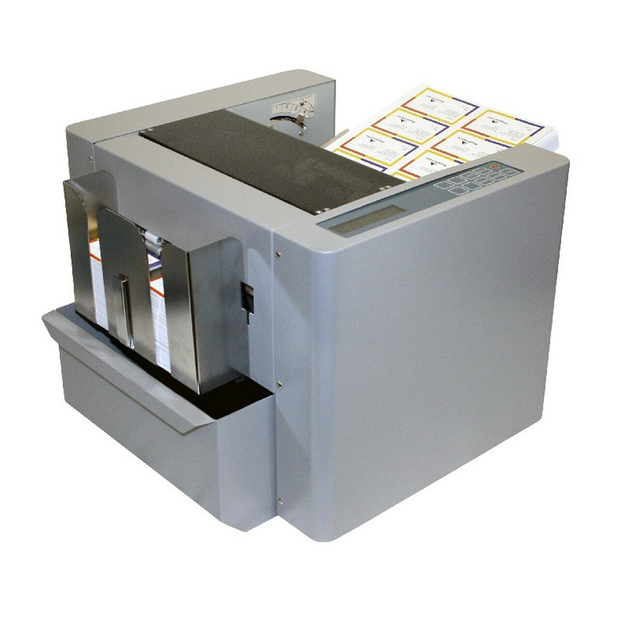
- Page 1 DocuCutter CC-228 SERVICE, PARTS and WEEE MANUAL Rev. 042013 Effective from: S/N 881041304078...
-
Page 2: Delare Od Conformity
IEC61000-4-8 IEC61000-4-11 EN60950-1 IEC60950-1 EN50581 CISPR 16-2-3 CISPR 16-2-1 CISPR 16-2-2 Keeper of the CE technical file in the European Community: Duplo International Ltd. Hanskampring 6, Automated Precision House, Hamm Moor Lane, Addlestone, Surrey, KT15 2SD UK - 1 -... -
Page 3: Safety And Precautions
SAFETY PRECAUTIONS Always observe the cautions and warnings given below to prevent personal injury or property damage. Disposal of Waste Electrical and Electronics Equipment (WEEE) This symbol (the symbol of the crossed out wheeled bin) indicates that in European countries this product should not be disposed of as household waste. -
Page 4: Weee Information
WEEE information (for Europe) As a minimum the following substances, preparations and components has to be removed from any separately collected WEEE (Waste Electrical and Electronics Equipment). In this parts catalogue, these WEEE symbols are appended to corresponding parts in this parts catalogue. WEEE Symbol Meaning (Poly Acrylonitrile Butadiene Styrene) Plastic Material... -
Page 5: Precaution In Maintenance And Handling
Precautions in Maintenance and Handling Repairs should be performed by qualified service personnel. WARNING: 2.1 To avoid the risk of touching to any hot spot on UV Curing section to cause injury, system has to be cool down before performing any services procedure in curing section. 2.2 To avoid the risk of electrical shock, disconnect the machine from the A.C. -
Page 6: Table Of Contents
Contents Page Delare od Conformity..................1 Safety and Precautions..................2 WEEE Information....................3 Precaution in Maintenance and Handling ............4 Specification......................6 Explosive View and WEEE................... 7 2.1 Right Side Plate ASm................8 2.2 Left Side Plate Asm................. 9 2.3 Electric Panel Asm. -
Page 7: Specification
pecification Paper Size LT / Legal Size/ 9” x 14” (Max) Paper Weight 120gsm ~ 350gsm Feeder Capacity 75 sheets (200gsm) Receiving Tray 500 business cards Speed Up to 130 business cards per min Accuracy ± 0.3 mm Dimension 13.8” (W) x 15.4” (D) x 13” (H) Net Weight 60 lbs (27Kgs) Power... -
Page 8: Explosive View And Weee
Explosive View and WEEE(Fig.1) Index Name Q’TY 881-A00-000A Asm, Side Plate, R 881-B00-000A Asm, Side Plate, L 881-C00-000A Asm, Electric Panel 881-216-000A Cover, Front Safety 881-E00-000A Asm, Feed Table 881-F00-000A Asm, Feed Ramp 881-G00-000A Bar, 881-H00-000A Asm, Transmission Roller, Lowe, Front 881-K00-000A Asm, Transmission Roller, Lower, Rear 2.10... -
Page 9: Right Side Plate Asm
2.1 Right Side Plate Asm (Fig. 2) Index Name Q’TY 2.1.01 881-A01-000A Side Plate, Right 2.1.02 00R-000-1101 Rubber Foot 2.1.03 00B-000-0905 Angle Bracket 2.1.04 881-A04-000A Stopper 2.1.05 00A-000-1211 PCBA Asm, PCB, Power 2.1.06 00M-000-0403 Motor, SQ, 2.58V, 3A 2.1.07 881-708-0000 Crank, Knife Driving 2.1.08 881-707-0000 Bushing, OD8, ID6.2... -
Page 10: Left Side Plate Asm
2.2 Left Side Plate Asm (Fig. 3) Index Name Q’TY 2.2.01 881-B01-000A Side Plate, Left 2.2.02 00R-000-1101 Rubber Foot 2.2.03 00B-000-0905 Angle Bracket 2.2.04 881-B04-000A Stopper 2.2.05 00A-000-1121 PCBA Asm, PCB, Interface 2.2.06 00A-000-1601 Asm, PCB, LCD Interface PCBA 2.2.07 00A-000-1001 Asm, PCB, LOGIC PCBA 2.2.08 00M-000-0401... -
Page 11: Electric Panel Asm
2.3 Electric Panel Asm (Fig. 4) Index Name Q’TY 881-C01-000A 2.3.01 Plate, Electric Panel 2.3.02 00R-000-1101 Rubber Foot 2.3.03 00F-000-0003 Fan, DC 12V PCBA 2.3.04 00A-000-0161 Asm, Driver Box, Common 00T-000-1405 2.2.05 Transformer 00R-000-0301 PCBA 2.2.06 Rectifier Board 00F-000-0401 2.2.07 Emi Filter Type 00B-000-0959 2.3.08... -
Page 12: Feed Tray Asm
Feed Tray Asm (Fig. 5) Index Name Q’TY 881-211-000B 2.5.01 Tray, Feed, CC-228 2.5.02 881-E02-000A Shaft, Side Guide Sliding Bracket, Side Guide Mounting 2.5.03 881-E03-000A Standoff, 6.35 x 2.2mm 2.5.04 00S-000-5901 Side Guide, Feeder, CC-228 881-105-000B 2.5.05 881-215-000A Thumb Screw, Feeder Side Guide 2.5.06 881-406-000A Shaft, Pivot, Feed Tray... - Page 13 - 12 -...
-
Page 14: Feed Ramp Asm
2.6 Feed Ramp Asm (Fig. 6) Index Name Q’TY 881-116-000A 2.6.01 Ramp, Feed 00B-000-0905 2.6.02 Angle Bracket 2.6.03 881-F03-000A Asm, Separator 2.6.03.01 881-F03-010A Base, Separator Asm 2.6.03.02 881-F03-020A Plate, Separator Asm Stop 2.6.03.03 881-F03-030A Bracket, Separator Sitting 2.6.03.04 881-F03-040A Pin, Separator Spring Holding 2.6.03.05 881-F03-050A Spring, Separator 2.6.03.06 881-F03-060A... -
Page 15: Front Lower Transport Asm
2.8 Front Lower Trasport Roller Asm (Fig. 7) Index Name Q’TY 881-H01-000A 2.8.01 Roller, Transport, CC-228 2.8.02 00G-M10-1910 Gear, M1, 19T, ID10 2.8.03 00B-F19-80ZZ Ball Bearing, LF-1980ZZ Collar, OD16, ID8 2.8.04 00C-016-080A 08P-51G-0800 2.8.05 Pulley, 0.8 P,51G,ID8 Fig. 7 - 14 -... -
Page 16: Rear Lower Transport Roller Asm
2.9 Rear Lower Transport Roller Asm (Fig. 8) Index Name Q’TY 881-H01-000A 2.9.01 Roller, Transport, CC-228 2.9.02 00G-M10-1910 Gear, M1.0, 19T, ID10 2.9.03 00B-F19-80ZZ Ball Bearing, F-1980ZZ Collar, OD16, ID8 2.9.04 00C-016-080A 08P-51G-0800 2.9.05 Pulley, 0.8 P,51G,ID8 2.9.06 00B-MXL-082C Belt, 0.2P, 82MXL, 8mm Fig. -
Page 17: Front Upper Transport Roller Asm
2.10 Front UpperTransort Roller Asm (Fig. 9) Index Name Q’TY 881-L01-000A 2.10.01 Roller, Upper, Transport, CC-228 2.10.02 00G-M10-1910 Gear, M1.0, 19T, ID10 Nylon Graphite Gasket, OD14, ID8.2 2.10.03 881-L03-000A Nylon 2.10.04 00H-L12-800A Housing, 1280 Ball Bearing (00H-000-0501) 00B-F12-80ZZ 2.10.05 Ball Bearing, F-1280ZZ 2.10.06 00B-L12-80ZZ Ball Bearing, L-1280ZZ... -
Page 18: Rear Upper Transport Roller Asm
2.11 Rear UpperTransnsport Roller Asm (Fig. 10) Index Name Q’TY 881-M01-000A Roller, Transport 2.11.01 2.11.02 00G-M10-1910 Gear, M1.0, 19T, ID10 Nylon Graphite Gasket, OD14, ID8.2 2.11.03 881-L03-000A Nylon 2.11.04 00H-L12-80ZZ Housing, 1280 Ball Bearing, Transport Rocker 00B-F12-80ZZ 2.11.05 Ball Bearing, F-1280ZZ 2.11.06 00B-L12-80ZZ Ball Bearing, L-1280ZZ... -
Page 19: Feed Roller Asm
2.12 Feed Roller Asm (Fig. 11) Index Name Q’TY 881-N01-000A 2.12.01 Shaft, Feed Roller 2.12.02 00B-0UF-L001 Pillow Block Ball Bearings, UFL-001 2.12.03 00R-000-1502 Feed Roller, CC-228 881-N03-000A Core, Feed Roller 881-N04-000A 2.12.04 Shaft, Feed Driving 2.12.05 162-107-0400 Bushing, OD7, ID6 2.12.06 00B-062-01ZZ Ball Bearing, 6201ZZ... -
Page 20: Cutter Transmission Asm
2.13 Cutter Transmisaion Asm (Fig. 12) Index Name Q’TY 881-704-000A 2.13.01 Knife, Upper. CC-228 881-P02-000A 2.13.02 Plate, Upper K NIFE OUNTING 2.13.03 881-719-000A Link 2.13.04 881-707-000A Bushing, OD8, ID6 881-P05-000A 2.13.05 Shaft, Knife Driving 2.13.06 00B-F19-10ZZ Ball Bearing, F-1910ZZ 2.13.07 881-721-000A Arm, R, Knife Driving... -
Page 21: Cutting Knife Asm
2.14 Cutting Knife Asm (Fig. 13) Index Name Q’TY 881-711-000A 2.14.01 Chassis, Cutting Knife Mounting 881-705-000A 2.14.02 Knife, Lower, CC-228 2.14.03 881-714-000A Asm, Middle, Upper Knife Holding Spring 2.14.03.1 881-714-010A Spring, Middle, Upper Knife Holding Spring Asm 2.14.03.2 881-714-020A Pin, Middle, Upper Knife Holding Spring Asm 2.14.03.3 881-714-030A Bushing, Middle, Upper Knife Holding Spring Asm... - Page 22 Fig. 13 - 21 -...
-
Page 23: Slitter Asm
2.15 Slitter Asm (Fig. 14) Index Name Q’TY 881-801-000A 2.15.01 Chassis, Slitter, 2 x 3.5” 881-801-010A Chassis, Slitter, 5.47X 4.21” 881-803-000A 2.15.02 Side Plate, L, Slitter 881-802-000A Side Plate, R, Slitter 2.15.03 881-805-000A Shaft, Slitter, Lower 881-804-010A 2.15.04 Shaft, Slitter, Upper, 2x3.5” Slitter 881-804-020A Shaft, Slitter, Upper, 5.47x4.21”... - Page 24 Fig. 14 - 23 -...
-
Page 25: Slitter Chassis Asm
2.16 Slitter Mounting Chassis Asm (Fig. 15) Index Name Q’TY 881-S01-000A 2.16.01 Chassis, Slitting Module Mounting 2.16.02 881-S02-000A Stud, Rear Safety Cover 2.16.03 00M-000-0002 Magnet, Rear Cover Position 2.16.04 881-111-000A Thumb Screw, Slitting Module Fastening 881-111-010A Spring, Compression, Slitting Module Fastening Fig. -
Page 26: Electrical Wiring Diagram
Electrical Wiring Diagram - 25 -... -
Page 27: Sensor Voltage Measurement
Sensor Voltage Measurement Sensors play an important role in monitoring and tracking the flow of the media inside of machine. A majority of stall conditions could be sensor related. Therefore, a digital multi-meter (DMM) is used for measuring the voltage reading of the sensors, and assuring proper alignment. 1. -
Page 28: Cutting Factor Calibration
Calibrations The calibration allows calibrate cutting mark, cutting length, offset and top margin by: ◎Select Job #4 ◎Holding for 5 seconds. mark:50 length:50 offset:50 margin:50 is displayed. ◎Tip on to select the item you are going to calibrate. ◎Tip on to save when the calibration is done. - Page 29 Cutting Mark ◎On job #4 to hold then tip on to set cutting mark, cut a printed sheet with mark, make sure the leading edge of the mark to cutting line is 3mm ◎ Select mark:50, if the cut mark leading edge to cutting line is greater or smaller than 3mm, tip on to adjust.
-
Page 30: Feed Tray Tension Adjustment
Feed Tray Tension Adjustment Factory setting the spring position as shown below: Increase Tension Decrease Tension - 29 -... -
Page 31: Paper Weight
Paper weight Adjust paper weight settings if paper is skewing or miss-feed.Set 1 or 2 for lighter paper and 4 or 5 for heavier paper. 1. Hold for 4 seconds. 2. Press to select settings 1-5. Use table below for references. 3. -
Page 32: Top Margin Parallel Adjustment
Top Margin Parallel Adjustment 1. Power off 2. Remove the rear cover 3. Using a 300gsm or 14 pt. sheet as gauge, rotate the feed roller by hand to feed it into apex of registration roller firm. 4. Underneath the feed tray has 5.5mm nut to hold the side guide, loosen the nut and align it against the paper to make it straight. -
Page 33: Self-Diagnose
Self-diagnose for Malfunction The system provides a unique feature to help service people pin point the sensor malfunction, detail procedure as below: Firmware Version: 01 Sensor Scan: OK 20.1 Hold then turn the power to on, is displayed 20.2 using a piece of paper to trigger the sensor, the sensor on the interface board connection are showing as below. -
Page 34: Error Message And Trouble Shooting
Error Message and Trouble Shooting Error Message Trouble Shooting Miss Feed 1.Check S1 voltage 2.Check feed motor belt 3.Check pulley screw 4.Check motor detent torque, if no torque 5. Replace driver board Jam in Sensor 2 1.Check S2 2.Adjust the feed tray tension 3.Adjust the ramp 4. - Page 35 No Power 1. Check Fuse 2. Check power plug 3. Check power board has 5V and 36V output Paper buckled at feed ramp 1. Adjust the feed tray tension spring position - 34 -...
-
Page 36: Recommended Spare Parts
Recommended Spare Parts List Part Name 00S-000-6112 Switch, Power Entry 00F-000-3006 Fuse, Time Delay, 3.15 A, 250V 881-102-0002 Key Pad, Staple 881-102-0003 Key Pad, CC-228, Cutting Factor 881-112-0000 Module, Slitter, 2 x 3.5” 881-112-0051 Module, Perforator 881-112-0052 Module, Scoring 881-112-0004 Module, Slitter, 4 x 8”... - Page 37 881-403-000C Spring, Feed Tray Tension, Inner 00F-000-0003 Fan, DC, 12V 00A-000-0161 Asm, Driver Box, L298 00A-000-1402 Asm, PWB, Driver, L298 00F-000-0401 Filter, AC Line 00S-000-6101 Switch, 115/230V Selectable 00M-000-0403 Motor, SQ, 2.58V, 3A 00M-000-0401 Motor, SQ, 2,8V, 1.7A (Alternative 3.9V, 1.2A) 00R-000-0301 Rectifier 881-704-000A...
Need help?
Do you have a question about the DocuCutter CC-228 and is the answer not in the manual?
Questions and answers