Table of Contents
Advertisement
Advertisement
Table of Contents

Related Manuals for Duplo DocuCutter DPC-400


Summary of Contents for Duplo DocuCutter DPC-400
- Page 1 DocuCutter DPC-400 Digital Die Cutter Operation Manual Revision: 111519AP...
-
Page 2: Table Of Contents
CONTENTS 1. User Notes………………………………………………………………………………3-6 2. Frame and Parts…………………………………………………………………………7 2-1 List of Parts (1)………………………………………………………………………7 2-2 CUTTER FRAME-………………………………………………………………………8 2-3 CUTTER FRAME-………………………………………………………………………8 2-4 CUTTER FRAME-………………………………………………………………………8 2-5 Sheets Pre-load Platform………………… …………………………………………9 3. Operation guide………………………………… ………………………………………9 3-1 Installation………………………………………………………………………… 10 3-2 Cutting Tools Installation……………………………………………………………12 3-3 Turn on/off………………………………………………………………………… 13 3-4 Cut Depth and Tools Selection Setting………………………………………………14 3-5 Offset for Creasing Wheel Tool ……………………………………………………... - Page 3 5-3 Suction…………………………………………………………………………………33 5-4 Reset……………………………………………………………………………………33 5-5 Enter……………………………………………………………………………………33 5-6 Communication…………………………………………………………………… …33 6. Q & A of Alarms……………………………………………………………………………34 7. Maintenance…………………………………………………………………………… 35 8. Specification…………………………………………………………………………… 36 Warranty…………………………………………………… ……………………………… 37...
-
Page 4: User Notes
1. User Notes 1>SAFETY RULES After receiving the machine, if end users require any further modification or change of one part or several parts of the machines, they are obligated to advise the machines back to the manufacture for this treatment. We do not have any legal responsibilities if the breakdown of the machines or operator’s injuries is caused by the importer’s modifications or changes to one part or several parts of the machines performed by end users. - Page 5 1.3 Safety Issues & General Safety Rules DO NOT 1. Read and understand this manual before 1. Do not attempt to operate or service the machine attempting to operate or service the without reading and understanding this manual. machine. 2. Be familiar with the machine safety rules 2.
- Page 6 2.INTRODUCTION 2.1What is the DocuCutter DPC-400 Does DocuCutter DPC-400 is design for cutting and creasing to the digital printed material, such as labels, cards and packing cartons on demand. 2.2 Symbol Description This manual’s symbols correspond to the specific area on the machine. These safety warnings are placed to protect both the user and anyone within the machine’s vicinity.
- Page 7 2.3 Name Plate 2.4 USAGE PRECAUTIONS 2.4.1 Before Operation a. Understand emergency stop button and main power location. In addition, normal operation must be confirmed. b. Tools and sundries should not be put on the machine. c. No obstacles should surround or be placed on top of the machine. d.
-
Page 8: Frame And Parts
2.5.4 Others a. Damaging all external and internal panels and controls is forbidden. b. Do not cover each button and switch. c. The machine should be kept clean at all time. d. Warning signs and tags on the machine should not be removed or destroyed. If you have any questions, please contact your agent or dealer. -
Page 9: Cutter Frame
2-2 CUTTER FRAME- 2-3 CUTTER FRAME 2-4 CUTTER FRAME-... -
Page 10: Sheets Pre-Load Platform
2-5 Sheets Pre-load Platform... -
Page 11: Operation Guide
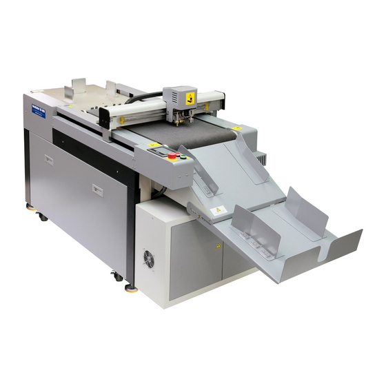
3. Operation guide 3-1 Installation Key Components 1. Feeder 2. Conveyor Belt 3. Cutting Head 4. Control Panel 5. Stacking Tray 6. Electric box... - Page 12 Installation Requirement ➊ a. Long arm forklift or crane at less 1 tons b. It requires a proper area for placing the cutter, about 79CM*230CM, the floor should be as flat as possible. c. It requires a clean room without EMI or static interference and operates under circumstance with humidity of 50-80%Rh and 20-25℃.
- Page 13 Compressed Air Installation ➌ 1. Incoming Air Adjuster No.1 - Adjust the air pressure to 0.3-0.6Mpa, 2. Adjust valve No. 2 to 0.2-0.3Mpa. No.1 No.2 Input...
-
Page 14: Cutting Tools Installation
3-2 Cutting Tools Installation Select the type of tool you need. Tool Name J201 J202 J205 J206 J208 Paper Type Paper/Card Paper/Card Card Stickers Sticker Paper Thickness 120-300gsm 150-400gsm 400-1kg Sticker or less (gsm) than 300gsm ➊ Blade Installation Procedures a. - Page 15 Creasing wheel installation 1&2 are the Allen screws, those two screws use for fix the crease wheel .Number 3 is the screw which use for pull the wheel holder and adjust the center of wheel blade . a. loosen1&2 then loosen 3 b.
-
Page 16: Turn On/Off
➋ Press Green Starting Button .. The cutter starts initializing..The cut system starts in 10 seconds and displays welcome page: Duplo USA ➌ Click and the cutter starts to reset. Verify no people within electric appliances area before turns on main power supply. - Page 17 Main Screen To enter the TEST menu To enter the Setup menu To turn the pump ON or OFF To reset the machine to the home position To resume the job TEST SCREEN...
- Page 18 Test Motions Head Motion Depth Origin Knife Depth: Adjusts the knife depth. Back Origin: Head Knife Action UP Arrow The higher the number the lower the Unit goes Feeder unit goes. postion Knife1 Depth: Adjusts the Knife1 Front Origin: Head Knife1 Action DOWN Arrow depth.
- Page 19 TOOL SELECT SPEED SP1 to SP8: Define the Knife1 Speed: Maximum speed it can Knife1 Acc: Acceleration speed of tool used reach Knife1 - None 500 (default) 3500 (default) - Knife Cut Speed: Maximum speed of Knife Cut Accel: Acceleration speed of Knife - Knife1 tool 3500 (default)
- Page 20 WHEEL TOOL SETTING DELAY (Not Used) ANGLE Wheel Down Speed: Maximum down speed of wheel Lifter1 Delay: 0 Pen Dec Angle: 0.0 700(default) Wheel Speed: Maximum speed of wheel Knives1 Delay: 0 Pen Stop Angle: 20.0 700 (default) Wheel Acc: Acceleration Speed of Wheel Cut Up: 0 Cut Dec Angle: 0.0...
- Page 21 OFFSET ADJUST X OFFSET Y OFFSET CURSOR Calibration Ratio: Adjusts the pulses of the X Calibration Ratio: Adjusts the pulses of the motor. X motor. -If the motor stops short of the stop positon -If the motor stops short of the stop X-Location: 10.0 adjust number to positive (+) positon adjust number to positive (+)
- Page 22 ADVANCE ADVANCE_b ADVANCE_c ADVANCE_a Auto-return: Head returns to set Knife Comp: Adjusts the angle of positions corner cut Off= stays at its current position -If the angle is rounded, increase the after cuts Password Input: 8888 value Back= goes to starting position -If the angle has point, decrease the Max= goes to the corner of the value...
- Page 23 Extended Setup Rolling Repeat: Table repeat previous job IP: IP address Material Type: Board (default) Vacuum Sucker 1&2: ON (default) Feed Length: You can adjust the length to accommodate a longer sheet above 600mm.
- Page 24 Auto Repeat: Machine will run the same job continuously Factory Reset: resets machine...
- Page 25 CALIBRATION RATIO X Line Y Line Excepted Line Actual Line 1. Draw a 200mm line on the program and send to the machine. - If the Actual line is short of your Expected line, increase the Calibration ratio. - If the Actual line is longer than Expected line, decrease the Calibration ratio. X and Y TOOL OFFSET CALIBRATION Expected Actual...
- Page 26 ADVANACE_a CALIBRATION Knife and Knife1 Compensation Flared Perfect Round 1. Make a 100mm X 100mm square and test on blank sheet. 2. Check the corners of the document. a. If the angle is rounded, Increase the value. b. If the angle is flared, Decrease the value. Wheel Offset Adjustment 0 Degrees 1.
-
Page 27: Cut Depth And Tools Selection Setting
3-4 Cut Depth and Tools Selection Setting ➊Tools Selection Enter the main page, click “SETUP” button to enter into the menu and click “TOOLS” button, popping up window of tools selection SP1-SP8. Select tools as required. Click SP1-SP8 and set the tool name to each number which you used often. For example: SP1 to knife .Sp2 to knife1, Sp3 to wheel ➋... -
Page 28: Offset For Creasing Wheel Tool
3. Click “Knife Action” to check knife depth. If the blade tip does not reach to table mat click “knife action” to lift up tool, then adjust depth value again. Repeat Step until the blade touches the mat. 4. Once the blade touches mat you’re done. Continue these steps for “knife1” depth setup. A. - Page 29 click “SETUP” button and then click “ADVANCE” button to enter angle settings. Change deflection angle value by clicking “Wheel offset" button on column “ADVANCE_a” Offset the cutter every time as deflection angle changes, otherwise any changes would come to effect. Repeat above settings till creasing wheel is parallel with Y axis. Click “Back” a fter setting finishes.and reset machine.
-
Page 30: Data Transmission Settings
3-6 Data Transmission Settings PC Settings ➊ Click “internet” on the desktop, click “Network and Sharing Center” to enter the control panel. Click “Local Connection” to enter the panel, click “Property” and select “Internet protocol 4” to enter IP setting. Select “using following IP address”, input:192.168.0.XX,or router IP. Click “Enter” after finishes. -
Page 31: Camera Settings
➋ IP SETTING After initializing, click connection on the main menu, IP address setting pops up, IP address set as 192.168.0.250, after finish setting, IP address will be saved automatically (Note:Keep the computer and the cutter on the same segment, otherwise disconnected). 3-7 Camera Settings... - Page 32 Click on the desktop, software starts tracking the cutter. The cutter will show on the list, IP settings are required before connection. Place the mouse over the device which needs to be edited, Click “edit”. Setting IP address as192.168.1.X,IP address of computer as 192.168.1.X+1,same as 3-5, select “local connection2”...
- Page 33 Caution: IP address of the cutter must be the same segment as that of the local router and PC, otherwise data transmission may fail. Restart the cutting system after IP settings is done.
-
Page 34: Software
4. SOFTWARE 4-1 Software Installation ➊Software Installation Duplo USA Double click ****Setup.exe Click “Next” and install the program on non-system disk, click “Next” to continue the installation of click “Close” to finish the installation. -
Page 36: Print Setup
4-2 Print Setup Duplo USA, 1. Open click “File” menu > “Printer” and set cutter model. LST0604 2. Then click “Print-Mode” and set IP address from the machine. 3. Select “Compatible old ma c”. -
Page 37: Print Files
4-3 Print Files Duplo USA, Open click “File” menu > Open, and choose files required. - Page 38 Click “Open” then come to the page as below. Choose proper “Unit”, “Scale-size” and click “OK” button to open the given file. Press “F12” on the keyboard to print the file.
- Page 39 After Click that “Print” button and Driver will send file to machine automatically.
-
Page 41: Camera Registration
4-4 Camera Registration Duplo USA ➊ Click “Setting”_setting_ in the menu of and select “Camera Locator (H)” in the drop-down box of “Loc-type” Duplo USA ➋Re-Open and click “Icon” button to pop up camera registration window. Click “Open and select required file, then open “Auto Task”, select the same file, set cut file”... -
Page 43: Setup
Cautions: IP address of the cutter must be the same segment as that of the local router and PC, otherwise data transmission may fail. The introduction of this part is a just basic information for operation. Please refer to details of JWCS Help offered separately. - Page 44 Tool Selection: Duplo USA The expected shape comes out, After defined the color of the sample of SP1, SP2, e.g. SP1 as the knife to output the rectangular. SP2 as the knife1 to output the circle. offset Example:...
- Page 45 Warning; Existed parameters of offsets are factory defaults, which is required to be followed strictly, otherwise there would occur equipment damages and unexpected risks. Example of gradient coefficient adjustment If the actual cut output is like what shows below as process a square: Select “SETUP”...
- Page 46 6. Q & A of Alarms Alarm Solution 1. Cut file is over the working size of the cutting table, please select correct machine model Duplo USA Duplo USA 2. Cut file is over valid work area of...
- Page 47 please move the file within the valid work area. This is of safety protection. Screen is locked as a given job finishes. Click “ENTER” to resume normal home screen This is self-detection of the cutter. Solution: cut off the power supply and verify cutting head is ok, restart the system in 20 seconds.
- Page 48 Dedusting Overhaul Air compressor Draining Clean Compressed air Draining Clean pressure meter Rails Dedusting Transmission parts Fastening Overhaul Professional Cutter as a whole Clean Overhaul overhaul Clean Kill virus 8. Specification Model DocuCutter DPC-400 EN touch screen Max. Speed 800mm/s...
- Page 49 Max. cutting thickness ≤400gsm {0.42mm varies from different media) Media Folding carton, Sticker, art paper, plastic film Repeat Precision ≤0.1mm Catch 4G & 512MB File Forma HP-GL compliant Data Interface Ethernet Transmission Linear rail Vacum Pump Power 1.5KW/50HZ Power Supply 220V±10%/50/60HZ Warranty One year warranty except consumables , full-life time maintenance for hardware of the...
- Page 50 Product Name: Product model: Series Number: Purcahse date:...
Need help?
Do you have a question about the DocuCutter DPC-400 and is the answer not in the manual?
Questions and answers