
Subscribe to Our Youtube Channel
Related Manuals for Duplo DocuCutter CC-330


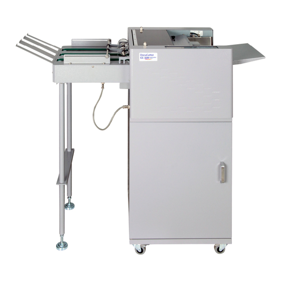
Summary of Contents for Duplo DocuCutter CC-330
- Page 1 DocuCutter CC-330 Service and Parts Manual Before doing service, read this manual. Follow all safety precautions. Duplo USA Corporation 3050 S. Daimler St, Santa Ana, CA 92705 www.duplousa.com Revision: 012213...
- Page 2 SAFETY PRECAUTIONS Always observe the cautions and warnings given below to prevent personal injury or property damage. The degree of danger and damage that could occur is indicated on two levels by the following marks. WARNING: Ignoring this mark could result in the possibility of serious injury or even death. Ignoring this mark could result in the possibility of injury or physical damage CAUTION : The following graphic symbols indicate the various types of action to be performed or avoided.
- Page 3 Do not use solvent inside or near the unit (e.g. when cleaning the unit). Such solvents may damage the rubber rollers and resin inside the unit, resulting in malfunctions. Make sure that the combined power consumption of the appliances to be connected does not exceed the capacity rating of the power outlets or plug receptacles.
- Page 4 Do not install this unit in a location where there is excessive humidity or where contact with water is possible. Poor choice of location could result in deterioration of the insulation, a fire or an electrical shock. Disconnect the power plug from the power outlet before attempting to move this unit. Failure to do so could result in power cord damage, a fire or an electrical shock.
- Page 5 Precautions in Maintenance and Handling Repairs should be performed by qualified service personnel. WARNING: To avoid the risk of electrical shock, disconnect the machine from the A.C. power source before performing any services procedure. The hardware used is METRIC. Replace hardware only with the same size as was originally used. Observe caution when cutting cable “tie-wraps”...
-
Page 6: Table Of Contents
Contents . Introduction ......................6 . Specifications ....................... 6 . Control Panel ....................... 7 . Key Components ....................8 . Parts on Top of the Frame ..................9 . Cutting Knife Assembly..................11 . Slitter Module ...................... 13 . Parts on Operating Side ..................15 . -
Page 7: Introduction
. Introduction The DocuCutter CC-330 is designed to simplify business card, photo and post card cutting in letter size which printed by digital press, color laser printer or inkjet image printer in one pass. . SPECIFICATIONS Paper Size LT, LG, LD, 12 x 18 and 13 x 19... -
Page 8: Control Panel
. CONTROL PANEL Keys Function Start and Stop the cutter Change job Select batch count 1. Clear paper jam in case of S3 error. 2. Increment settings by 0.1 mm when press. 1. Confirm job and batch count setting. 2. Decrement settings by 0.1mm when press. Save settings Enter program mode Set top margin... -
Page 9: Key Components
. KEY COMPONENTS Index Part Name Remarks 882-100-000A DocuCutter, CC-330 882-200-000A Stand, DocuCutter CC-330 882-201-000B Cover, Top, Stand, CC-330 882-300-000A Conveyor, DocuCutter CC-330, 21” 882-300-000B Conveyor, DocuCutter CC-330, 15”... - Page 10 Index Part No. Description Qty. Remarks 882-200-020A Waste Bin...
-
Page 11: Parts On Top Of The Frame
. PARTS ON TOP OF THE FRAME Index Part Name Remarks 1.01 882-101-000A Tray, Feed Extension, CC-330 1.02 882-102-000A Side Guide, R, Feeder, CC-330 1.03 882-103-000A Lever, Feed Thickness Scale, CC-330 1.04 881-118-000A Case, R, CC-330 1.05 882-112-000A Asm, Cutting Knife, CC-330 AAO-BCC330SLTS 1.06 882-112-010A... - Page 12 2&3 1 2&3 Index P/N Part Name Qty Remarks 00B-882-010A Bracket, Top Cover 999-B330 SBT 3x6 Screw 999-N1 M3 Nut Goes with 999-B330 881-107-2000 Trigger ...
- Page 13 Index P/N Description Remarks 1.22 00B‐000‐PB10 ...
- Page 14 1.01 Index Part Name Qty. Remarks 1.13.01 00S-000-1604 Separator, Feed...
- Page 15 Index Part Name Remarks and 1.14.01 882-114-010A Frame, Auxiliary Feed Roller Asm 1.14.02 882-114-020A Roller, Auxiliary Feed 1.14.03 882-114-030A Shaft, Auxiliary Feed 1.14.04 882-114-040A Bushing, Auxiliary Feed 1.14.05 00B-MXL-126A Belt, 126MXL, 6.4mm 1.14.06 882-114-060A Bushing, Auxiliary Driving Shaft 1.14.07 882-114-070A Spacer, Auxiliary Driving Shaft 1.14.08 882-114-080A...
- Page 16 . Cutting Knife Asm 882-105-000A Index Part Name Remarks 1.05.01 882-105-010A Knife, Upper, CC-330 1.05.02 882-105-020A Knife, Lower, CC-330 1.05.03 882-105-030A Bar, Knife Asm Mounting, CC-330 1.05.04 881-713-0000 Bracket , L, Upper Knife Mounting, CC-228 1.05.05 881-714-0000 Bracket, R, Upper Knife Mounting, CC-228 Asm, Spring, Middle, Knife Holding, CC-228 1.05.06 881-714-0000...
- Page 18 . Slitting Module, 2” x 3.5” 882-112-010A Index Part Name Remarks 1.06.01 882-106-010A Frame, Slitter, 2x3.5”, CC-330 1.06.02 882-106-020A Cover, Upper, Slitter, CC-330 1.06.03 882-106-030A Cover, Lower, Slitter, CC-330 1.06.04 882-106-040A Cover, Top, Slitter, CC-330 1.06.05 00H-000-0015 Handle, Slitter, CC-228 1.06.06 882-106-060A Shaft, Slitter, CC-330...
- Page 19 882-106-260A Pin, Ø4 x 8L...
-
Page 20: Parts On Operating Side
. PA RTS ON OPERATING SIDE Index Part Name Remarks 1.3.01 00A‐000‐1501 Asm, Control Panel 1.3.02 00C‐000‐0051 Cable, LCD Interface 1.3.03 00D‐000‐0303 Asm, Display, LCD 1.3.04 882‐130‐400A Spring, Transport Roller Holder 1.3.05 882‐130‐500A Holder, Upper Transport Roller 1.3.06 00B‐000‐F608 Ball Bearing, F608ZZ 1.3.07 00S‐000‐1513 Sensor, Interrupter... - Page 21 27, 28 24 25 26 22 23 Index Description Remarks 1.3.22 00S-882-F01A Shaft, Feed 1.3.23 00R-882-TL1A Roller, Transport, Lower...
-
Page 22: Parts On Non-Operating Side
. PARTS ON NON OPERATING SIDE Index Part Name Remarks 1.4.01 00B-000-0451 Belt, 171mxl, 10mm 1.4.02 882-140-200A Roller, Idler, CC-330 1.4.03 00M-000-0403 Motor, SQ, 75mm, 3A, 2.58V 1.4.04 00M-000-0403 Motor, SQ, 75mm, 3A, 2.58V 1.4.05 882-140-050A Block, Cutting Knife Driving, CC-330 1.4.06 881-403-0000 Spring, Feed Tray Tension, CC-228... - Page 24 . PARTS UNDERNEATH OF THE FRAME Index Part Name Remarks 1.5.01 00A-000-0207 Sensor, Black 1.5.02 00M-000-0403 Motor, SQ, 3A, 2.58V 1.5.03 00F-000-0003 Fan, DC 12V 1.5.04 00A-000-1402 Asm, PCB, Driver 1.5.05 00A-000-0161 Asm, Driver Box 1.5.06 00C-000-0081 Cable, 34P, Driver to Interface 1.5.07 00R-000-0301 Asm, PCB, Rectifier...
- Page 25 . ELECTRIC PCB ASM Index Part Name Remarks 1.6.01 00A-00C-1001 Asm, PWB, Logic, CC-330 1.6.02 00A-000-1611 Asm, PWB, Display, LCD 1.6.03 00A-000-1121 Asm, PWB, Interface 1.6.04 00A-000-0161 Asm, Driver Box 1.6.05 00A-000-1211 Asm, PWB, Power 1.6.06 00A-000-1501 Asm, PWB, Control Panel 1.6.07 00A-000-1311 Asm, PWB, Relay, SF-205...
- Page 26 P/N 00A-000-1121 ASM, PWB, INTERFACE P/N 00A-000-0161 ASM, DRIVER BOX...
- Page 27 P/N 00A-000-1211 ASM, PWB, POWER P/N 00A-000-1501 ASM, PWB, CONTROL PANEL...
- Page 28 P/N 00A-000-1311 ASM, PWB, Relay, SF-205...
-
Page 29: Conveyor
. Conveyor Index Part Name Remarks 3.01 882-301-000A Asm, Pick Up Roller, CC-330 Conveyor 3.02 882-302-000A Belt, CC-330 Conveyor, 21” 882-302-000B Belt, CC-330 Conveyor, 15” 3.03 882-303-000A Ramp, CC-330 Conveyor 3.04 00S-M04-010T Thumb Screw, M4x10 3.05 08P-18G-0800 Pulley, 0.08P, 18G, OD 8mm 3.06 00B-MXL-106A Belt, 106MXL, 6.4mm... -
Page 30: Electrical Wiring Diagram
. ELECTRICAL WIRING DIAGRAM... - Page 31 . SENSOR VOLTAGE MEASUREMENT Sensors play an important role in monitoring and tracking the flow of the media inside of machine. A majority of stall conditions could be sensor related. Therefore, a digital multi-meter (DMM) is used for measuring the voltage reading of the sensors, and assuring proper alignment. .
-
Page 33: Replace The Feed Roller
. Replace the Feed Roller 1. Loosen the Feeder Roller Cover mounting screws 3 x on both side 2. Remove the Thumb Screw on top of Feeder Roller Cover 3. Remove the Feed Roller Assembly mounting screw... - Page 34 4. Remove the Auxiliary Feed Roller mounting screw as shown below 5. Loosen the Middle Feed Roller collar fastening screw, then the shaft can be sliding out to replace the roller...
-
Page 35: Feeding Test And Permanent Count
. Feeding Test and Permanent Count The system provides view permanent count, mark and feeding testing without cutting features by: ◎ Select Job #4 and set cutting mark to on by holding then tip on ◎ Hold for 5 seconds, “test mode 23”... -
Page 36: Calibration
.Calibrations The calibration allows calibrate cutting mark, cutting length, offset and top margin by: ◎Select Job #4 ◎Holding for 5 seconds. mark:50 length:50 offset:50 margin:50 is displayed. ◎Tip on to select the item you are going to calibrate. ◎Tip on to save when the calibration is done. - Page 37 Cutting Mark ◎On job #4 to hold then tip on to set cutting mark, cut a printed sheet with mark, make sure the leading edge of the mark to cutting line is 3mm ◎ Select mark:50, if the cut mark leading edge to cutting line is greater or smaller than 3mm, tip to adjust.
-
Page 38: Paper Weight
. Paper Weight Adjust paper weight settings if paper is skewing or miss-feed. Set 1 or 2 for lighter paper and 4 or 5 for heavier paper. 1. Hold for 4 seconds. 2 Press to select settings 1-5. Use table below for references. 3. -
Page 39: Pure Dark Image "Top Margin" Adjustment
. Pure Dark Image “Top Margin” Adjustment Pure dark image on whole image such as black, grey, grey, green blue…etc without 0.5” white boundary will causing top margin cutting variance due to sensitivity differential. Recommend to do “Top Margin” calibration. The calibration allows calibrate procedure as below: On job #4 to hold then tip on... -
Page 40: Feed Tray Tension Adjustment
. Feed Tray Tension Adjustment 1. Factory setting the spring position, black spring at position 3 and silver spring at position 1 as shown below: 2. If feed hopper tension set to scale 4, thin paper, still causing the paper buckled, and not get into the 1 set of transport roller, reallocate the spring mounting hole to the right to reduce the tension. -
Page 41: Feed Gap Adjustment
. Feed Gap Adjustment If double feed, turn the separator height adjustment screw clockwise to make the feed gap smaller. If paper is too thick and cannot be fed, turn the screw counterclockwise to open the feed gap. -
Page 42: Top Margin Parallel Adjustment
. Top Margin Parallel Adjustment 1. Power off 2. Remove the rear cover 3. Using a 300gsm or 14 pt. sheet as gauge, rotate the feed roller by hand to feed it into apex of registration roller firm. 4. Underneath the feed tray has 5.5mm nut to hold the side guide, loosen the nut and align it against the paper to make it straight. - Page 43 . Self-diagnose for Malfunction The system provides a unique feature to help service people pin point the sensor malfunction, detail procedure as below: Firmware Version: 01 Sensor Scan: OK 1. Hold then turn the power to on, is displayed 2. Using a piece of paper to trigger the sensor, the sensor on the interface board connection are showing as below.
- Page 44 . Error Message and Trouble Shooting Error Message Trouble Shooting Miss Feed 1.Check S1 voltage 2.Check feed motor belt 3.Check pulley screw 4.Check motor detent torque, if no torque 5. Replace driver board Jam in Sensor 2 1.Check S2 2.Adjust the feed tray tension 3.Adjust the ramp 4.
Need help?
Do you have a question about the DocuCutter CC-330 and is the answer not in the manual?
Questions and answers