Table of Contents
Advertisement
Quick Links
Advertisement
Table of Contents

Subscribe to Our Youtube Channel
Related Manuals for Duplo DPC-600PKG


Summary of Contents for Duplo DPC-600PKG
- Page 1 DPC-600PKG Cutting System Installation and Operation Manual Rev. 231215...
- Page 2 DECLARATION OF COMFORMITY PrintFinishing Co. Ltd., located at 625 Sec. II, Wende Road, Hsin-Pu 30544, Taiwan declares that the product compliances with the provision defined in the regulations as below. Regulation Machinery Directive Low Voltage Electromagnetic UL/CUL 2006/42/EC Directive Compatibility Product Model 2006/95/EC...
- Page 3 10. S ENSOR OCATION ........... 17 11. E RROR ESSAGE PART II DPC-600PKG DIGITAL DIE CUTTER ......20 ............20 1. I NTRODUCTION 1.1 What is the DPC-600PKG Does....................20 1.2 Symbol Description ........................20 1.3 Name Plate............................. 21 1.4 USAGE PRECAUTIONS ......................
- Page 4 6.4 Power Requirement ........................27 6.5 Clearance Requirements ........................ 27 ..........28 7. I NSTALLATION OF ATCHER ..........30 8. I NSTALLATION OF OOLS 8.1 Installation of Oscillating Tool ...................... 30 8.2 Press cut tool Installation Guide ....................31 8.3 Installation of Full Cut Tool ......................38 8.4 Installation of Kiss Cut Tool ......................
- Page 5 PART III STACKER ST-200I (OPTION) ........75 ............. 75 NTRODUCTION ............. 75 PECIFICATION ............75 LATE ............ 76 4. A CCESSORIES ........77 5. C ONTROL ANEL AND UNCTION ..........79 6. O PERATION ROCEDURE 6.1 Load the Paper ..........................79 6.2 Adjust the Jogger Clapping Plate Home Position ................
-
Page 6: Specification
Part I SF-300i Suction Feeder 1. Introduction The SF-300i feeder is an automatic air suction, top-feed feeder that offers cost effective and ox-on-Demand. increase thruput of the DPC-600PKG flat bed cutter for B 2. Specification Specifications SF-300i Suction Feeder Max. Paper Width 23”... -
Page 7: Accessories List
4. Accessories List Power Cord Back Stop Asm 00P-000-3007 USA SF-300i Product Manual Interface Cable 50cm Product Manual (Download from Website) Extension Plate Side Guide x 2 DPC-600PKG Cutter – Ejection Roller Asm - 6 -... -
Page 8: Key Components
5. Key Components - 7 -... - Page 9 Item Key Components Base Stand Feeder Body Conveyor Asm Conrol Panel LED Display LED Emergency Stop Feed Tray Back Stop Side Guide Leading Edge Index Sensor Suction Feed Components Blower Fan Double Feed Separator Upper 6-pin Interfaces with Cutter Lower 8-pin interfaces with Stacker Restart Brushless Motor Switch 6.
- Page 10 7. Control Panel and Function Key Function Keys Function Clear paper path and as composition key Reset error message on the display Tray down to reload the media The blower has 4 speed to select; the higher speed has stronger air flow. SP-1~SP-4 The thicker media needs higher speed.
-
Page 11: Loading Paper
No Function Composition Key Reset counter Default without adjustment 8. Loading Paper 8.1 Fan the paper and make in order to separate the sheets if feeding the thin stock 8.2 Load the Paper - 10 -... - Page 12 8.3 Setting the Guides and Back Stop. The feeder is right-hand side justify, please use the side guide and back stop to box the feed pile. *** Back stop always set in the center of the feed tray prevents skew feed.*** - 11 -...
-
Page 13: Operation Procedure
9. Operation Procedure 9.1 585mm (23”) Sheet width Setting. 1. Default Registration from factory is 530mm (B2+). It is good to run 2x18”, 13x19”, 20x14” long edge feed and short edge feed. 2. For 23” sheet width, please set it to 585mm which is 23”. Loosen the feed side guide screws (5x) and transport registration guide (6x) and re fastening it onto to 585mm position. - Page 14 9.2 Level Sensor Adjustment Substrates Range Abnormal Normal Cured Up Cured Up Cured Down 10mm 10mm 200~400gsm -1.0 2mm Thick Stock Note: The curled /curled down substrates are after Spot UV and laminated sheet. 9.3 Weight The paper is always in position to hold the paper pile doesn’t matter it is thick or thin which will be preventing the double feed especially 200gsm ~400gsm paper.
- Page 15 9.4 Pinch Roller Pressure Setting Thickness Piece of 200gsm Paper Strip to Adjust 1 x 200gsm Strip 2 x 200gsm Strip 3 x 200gsm Strip ********To set pinch roller little bit tight*********** 9.5 Separator Setting While using the Weight to hold the feed pile, the Separator is not necessary to use, If the weight still experiences double feed, please set the separator as below: 9.5.1 Think stock 200gsm~ 400gs a.
- Page 16 9.6 Setting the Clapper 9.6.1 Loosen the clapper holding Screw and push it aside. 9.6.2 Press to bring one sheet in to standby position 9.6.3 Move the clapper in and against the edge of the sheet. Be sure to eepk 0.5~1mm spacing. 9.7 Change Blower Speed The blower force is adjustable, thin stock say 200gsm set it to SP-2~3, thicker substrates set it to SP-4 by holding the...
- Page 17 10. Sensor Location Sensor No Description Function Feeding Sensor Make sure feeding is success Exit Sensor Standby Sensor is detected by cutter feeding signal Level Sensor Detect feed tray height Suction Fan On/Off Accurate feeding control - 16 -...
- Page 18 11. Error Message Error Code Symptom Action 1.1 Readjust side the guide 1.2 Check the media quality E001 Paper does not reach S3 1.3 Clean Sensor 3 if needed 1.4 Adjust the Level Sensor height 1 Paper does not reach to S2 1.1 Correct skew, readjust side guide 1.2 Check media not flat or curled E002...
-
Page 19: Recommended Spare Parts
Recommended Spare Parts Index Name DBM-24V-BL60 5.1.01.04 Brushless Motor, BL60M80-A, DC24V, 5.2A 00B-0XL-105A 5.1.01.06 Belt, 0.2P, 106XL DBD-0BL-1250 5.1.01.07 DC Brushless Motor Driver, BL-1250V, 24 / 48V, 6A B/B-000-2280 5.1.01.11 Ball Bearings, 608ZZ CHN-000-0035 5.1.01.14 Chain, 35 Segment, 00C-000-0504 CHN-000-0019 5.1.01.15 Chain, 19 Segment, 00C-000-0503... - Page 20 H/B-000-1612 5.1.10.07 Hard Bushing, OD16, ID12 O/W-000-FC16 5.1.10.08 One Way Clutch, FC-16, 162-109-080A 162-110020A 5.1.11.02 Asm, Pinch Roller, SF-200 00A-000-0177 5.1.11.09 Asm, Paper Sensor, Black 00A-00B-0021 5.1.12.07 Level Sensor Asm F/B-050-2320 5.2.06 Flat Belt, 50 x 2320 mm CUS-0GM-2015 5.2.09.04 Shock pad GM-2015 CUS-0GM-2518 5.2.09.05...
-
Page 21: Symbol Description
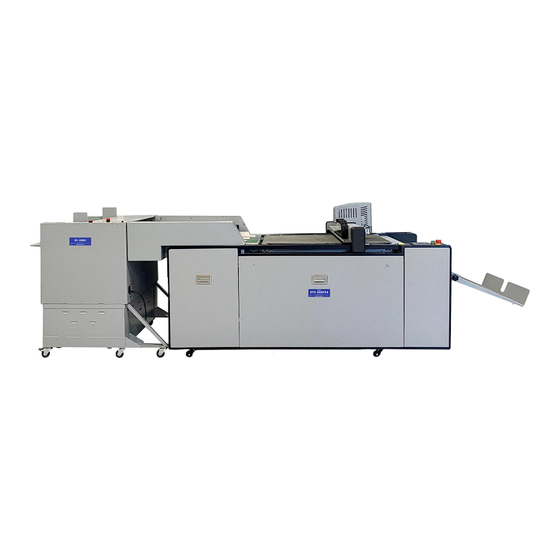
Part II DPC-600PKG Digital Die Cutter 1. Introduction 1.1 What is the DPC-600PKG Does. DocuCutter DPC-600PKG is design for cutting and creasing to the digital printed material, such as labels, cardstock, synthetic (may varies) and corrugated board for die cutting especially for packaging, Box-on-Demand. -
Page 22: Name Plate
1.3 Name Plate 1.4 USAGE PRECAUTIONS 1.4.1 Before Operation a. Understand emergency stop button and main power location. b. Tools and sundries should not be put on the machine. c. No obstacles should surround or be placed on top of the machine. 1.4.2 During Operation a. -
Page 23: Specification
2. Specification L31.5” x W23.6” Max Sheet Size w/o CCD L31.5” x W23.6” Max sheet size with CCD L17” × W11” (Long edge feed) Min Sheet Size Min Sheet Width 12” Maximum Paper Weight 400gsm or 3.6mm Thickness from feeder, > 3.6mm manual feed Minimum Paper Weight 200gsm 15-45 secs per 12x18”... - Page 24 3. Accessories Name Photo Remarks Check PCB-831-PCIE PCIe Server Adaptor For CCD 00C-831-0001 Cable, Ethernet, 01.53.0066 00W-831-0001 Wire, Grounding 00P-831-0001 Power Cord Key-831-0001 Key, Electric Cabinet Kit-831-0002 Kit, Screw Kit-831-0003 Kit, Tool 00T-832-0000 Hand Tool, Clip the blade 03.06.0161 while installation it onto tool holder 00T-831-J206 Tool Holder, J206,...
- Page 25 00T-832-J385 Tool, Press Cut, 03.06.0178 00T-832-J603 Tool, V-Cut, 03.06.0179 00K-832-603A Knife, V-Cut, 2 pieces as a set 01.49.0230 00K-832-603B Knife, V-Cut, 2 pieces as a set 01.49.0231 0CM-832-0250 Creasing Module, with 2.5mm Creasing Wheel 0CM-832-J380 Creasing Module, Install on the J380 machine CWR-831-J380...
-
Page 26: Product Overview
4. Product Overview Feeder Cutting Head Feed Side Guide Control Panel Feed Conveyor Stacker Cutting Conveyor 5. Unload and Unpack 5.1 Unload Requirement a. Crane loading greater 2,200 lbs (1000kg) b. Forklift loading greater 2,200lbs (1000kg) c. Car or tractor loading dimension match with the wooden crate. 5.2 Unpack Requirement Use 13/14mm Open-end Wrench, Box Wrench, and Power Box Wrench, Ladder, Scissors..etc. -
Page 27: Installation Requirement
. Installation Requirement 6.1 Cautions for Installation a. The machine should have good level and ventilation. b. Machine should not be allocated in damp or wet place. c. Machine should not be exposed in combustible or wet corrosive gases. d. Install the feed support chassis. e. -
Page 28: Optimum Environment
Avoiding accident the machine must be grounded according to electrical rule NO.3 c. Do not connect ground with the other machine which has leakage circuit breaker. 6.4 Power Requirement DPC-600PKG Cutter: 220V±10%, 60HZ, 15A 6.5 Clearance Requirements a. The machine should have at least 30”... - Page 29 7. Installation of Catcher Step Step 2 - 28 -...
- Page 30 Screw 1 use for fix catch tray position so that collect tray cannot fold down. Screw 2 use for making these two trays connect. Step 3 IInstallation of Ejection Roller Assembly - 29 -...
- Page 31 8. Installation of Tools 8.1 Installation of Oscillating Tool The oscillating too mainly used for foam board/pad, grey board, cardboard, KT board, PVC board, corrugate board, and other thicker/harder materials. Step 1 Loosen these two set screws with Allen key allows to press the cover down. Step 2 Make the blade direction face to the set screw.
- Page 32 8.2 Press cut tool Installation Guide Step 1 : Prepare the knife and the tools ①: 2 mm Allen key ②: Knife J383, J384 and 385 ③: Press cut tool: JWT-096-00-00 - 31 -...
- Page 33 Step 2: Use hand to pull the tool cap to remove the cap from the tool body ①: Tool body ②: Tool cap - 32 -...
- Page 34 Step 3: Use 2mm Allen key to lose the 2-knife lock screws ①: Knife lock screw ②: 2mm Allen key Step 4Insert the knife into the tool body, the knife edge should face the right side. The knife model and the knife lock screws should face the front.
- Page 35 - 34 -...
- Page 36 Step 5 Push the knife to the bottom, use Allen key to lock the 2 knife lock screws to lock the knife to the tool body Step 6Put back the tool cap and match the pin on the tool cap to the slot on the tool body and push the cap to fit into the tool body Step 7Rotate the knife adjust the ring to adjust the...
- Page 37 Step 10 Open the head cover, Insert the tool to the machine head oscillating tool holder, matching the notch on the tool with the notch on the tool holder ①: Notch on the tool ②: Notch on the tool holder - 36 -...
- Page 38 Step 11 Press down the lock button on the tool holder to release the tool holder. ①: Lock button slide down the tool to the bottom and release the lock button to lock the tool in the holder - 37 -...
- Page 39 8.3 Installation of Full Cut Tool Step 1 : Prepare the knife and the tools ①: 2 mm Allen key ②: Knife J383, J384, J385 ③: Full cut tool: - 38 -...
- Page 40 Step 2: Use the Allen key lose the tool lock screw on the tool and disassemble the tool ①: Tool body ②: Spring ③: Tool cap - 39 -...
- Page 41 Step 3: Insert the knife into the tool body and match the knife edge to the lock notch in the tool body to be in the same direction ①: Knife edge ②: Lock notch Step 4 Put the spring into the tool body ①: Spring ②: Tool body - 40 -...
- Page 42 Step 5: Put the tool cap onto the tool and match the tool lock screw with the lock notch to be in the same position ①: Tool lock screw ②: Lock notch Tight the tool lock screw to lock the tool cap to the lock notch The tool tail end can Use 2mm Allen key to adjust the knife sharp point to come out the tool cap , Base on material thickness that you can control the blade sharp...
- Page 43 Step 7 Prepare the tools ①: 1.5 mm Allen key ②: Full cutting tool Step 8: Insert the tool into the full cutting tool holder in the machine head, match the holder lock screw with the tool lock notch to be in the same position ①: Holder lock screw ②: Tool lock notch Step 9...
- Page 44 Drag down the tool several times to test if the Step 10 - 43 -...
- Page 45 8.4 Installation of Kiss Cut Tool Step 1: Prepare the knife and the tools ①: 2 mm Allen key ②: Knife J301 ③: Kiss cut tool: JWT-066-00-00 - 44 -...
- Page 46 Step 2: Loose the tool lock screw with the Allen key to remove the tool cap from the tool body ①: Tool cap ②: Spring ③: Tool body Step 3: Insert the knife to the tool body until the knife notch matches with the tool body top ①: Knife notch ②: Tool body - 45 -...
- Page 47 Step 4 Put the spring onto the knife body ①: Spring ②: Knife body Step 5 Put on the tool cap and tight it to the tool body. Step 6 Use the Allen key to tight the screw to lock the tool cap to the tool body - 46 -...
- Page 48 Step 7 Hold the tool tail and rotate the tool cap to adjust the Knife point expose distance from the tool cap ①: Tool cap ②: Tool tail Step 8 Press down the tool on the surface of the sticker material with a certain force. Then drag it along the flat step in the tool tail direction.
- Page 49 Step 10: Press the reset button to reset the machine Step 11 Prepare the tools. ①: Kiss cut tool with knife installed ②: 1.5mm Allen key - 48 -...
- Page 50 Step 12 Insert the kiss cut tool to the machine head tool holder,the flat step in the tool tail should facing the front direction ①: Flat step in the tool tail Step 13 Push the tool up and lock the lock screw with 1.5mm Allen key on the tool holder Step 14 Drag down the tool several times to test if it is locked tightly or not - 49 -...
- Page 51 9. Tools Installation Video Download https://www.duplousa.com/support/ 10. Cutting File Format 10.1 Common format The default file format for the machine is HPGL, the other adaptable file formats are HPG. PLT. DXF.PDF and EPS 10.2 Special format Machine can also import files exported the XML format file from the RIP software such as Onyx/Caldera PhotoPrint / PrintFactory.
- Page 52 2: Import the graphics in the art board, set different color to the related vector lines. Step Step 3: File menu --> export -- > export - 51 -...
- Page 53 4: Select the save type as DXF format and enter the file name Step Step 5: DXF the unit in the export menu should be millimeter for the file, then select OK - 52 -...
- Page 54 12. How to Export of Camera Locating Files There are two main register marks supported by our locator function: black circle ( ) and black cross ) respectively. The register marks size can be from 3 mm to 20 mm and the recommended register marks are 6 mm circles and 10 mm circles.
- Page 55 13. How to Export PLT Files in CorelDRAW 1: create a new art board, set width (X ) and height (Y ) according to machine size. Step Width (W): Machine X Direction Dimension Height (H): Machine Y Direction Dimension Unit: Recommended mm (mm) - 54 -...
- Page 56 2: Import the graphics in the art board, set different color to the related vector lines. Step 3: File menu --> export --> Export to the DXF Format Step 2) Export to the PLT Format - 55 -...
- Page 57 Width (W): machine X direction dimensions - 56 -...
- Page 58 Height (H): Machine Y Direction Dimensions Unit: mm plotter origin: lower left (machine origin) Pen: SP property (current device support SP1 to SP8) Color:CorelDRAW software contour color Pencil Color: The corresponding contour color can be adjusted after selecting the pen number Curve resolution (R): the unit is set to "mm ", the smaller the curve resolution value, the more arc points.
- Page 59 14. How to Generate and Export the Camera Locating Files The registration marks position for the CorelDraw is as same as the illustrator, and only the contour lines are retained. 15. DPC Connects Installation and Operation Download Link https://www.duplousa.com/support/ - 58 -...
-
Page 60: Computer Setup
16. Data Transfer Settings 16.1 Computer Setup While Computer started and ready, find the "network" icon on the desktop, right-click the network icon and Select Properties, Enter into the network and share center window, click "change adapter settings". After Click “Change Adapter Settings” to enter the local connection Window, Right - click on the Relevant local connection, Click "properties ", Double click \Protocol version 4 to enter IP settings, Select “use following IP Address”, then you can define the ip what you need. - Page 61 16.2 Connection DPC-600 and Computer, and the Software IP Setup Power on the cutting machine, after the machine reset finish, click the "Setup" button, enter the "Advanced " page, enter the" extended Settings "page. You will see machine IP address option, Set the IP to 192.168.0.250, click return after setting, IP address will be saved automatically (Note: make sure the computer and machine are in the same network segment, otherwise the machine cannot be connected).
- Page 62 For example: Set camera IP address as 1.2.3.5, Camera local connection Ip need set to same segment, such as 1.2.3.*(cannot same with camera software setup). Computer IP address setting method as below: Right click on the camera PCI Card local connection and click Properties,select internet protocol version 4(TCP/IPv4) and double click it.Select the “Use the following IP address”and set IP address:1.2.3.4,Subnet mask as 255.0.0.0,default gateway as 0.0.0.0) then click OK to save the setting.
- Page 63 The machine IP address, the net router (if use) and computer address must be set to the same network segment, otherwise they may not be connected. - 62 -...
-
Page 64: Operation Procedure
17. Operation Procedure 17.1 Function Key Function Function Suction Turn on/off the suction Manually Reset Reset to Home (X0, Y0) Enter Repeat the previous file Test Common Tool Testing Common Tool Set Up Tool Set Up Tool Depth Set Up Tool Depth Set Up - 63 -... - Page 65 17.2 Tool Selection and Set-Up “press to start” Click Click - 64 -...
- Page 66 Press “TOOL TO SELECT” There are SP1~SP8 for select the tool Name. You can name the Number for different tools as your needs. For Example: SP1: knife SP2: Wheel 17.3 Tool Depth Set-Up Press a. You can find Knife/Oscillating tool/wheel/K3 tools name with up/down button. b.
- Page 67 e. While you do test if the tool cannot cut the material thru, you can modify the depth value directly. *Please note that value cannot be over 0.5mm. For example, the depth value is 5. You can modify it less than f.
- Page 68 17.4 Tool Compensation Settings If the knife, creasing wheel, or oscillating knife is not parallel to the X direction. please can enter into the Tool Calibrate page and adjust the blade angle . You can find below page thru Click “Compensation” option which in the ADVANCE page. When creasing Arc/curve with creasing wheel that file diameter should bigger than 6mm.
- Page 69 17.5 Start After power on the cutter, the touch screen will take around 10s to initializing and show above page. Then Click the center of screen and the cutter head will move to home position. - 68 -...
- Page 70 17.6 Test Menu Items Functions Knife action Control the Tangential tool up/down. Oscillating tool action Control the Oscillating tool up/down. Wheel action Control the wheel tool up/down. Test speed Moving the speed when you press the direction key Test Temporary original position setting. Please refer to the red cursor to move the machine head to any position of the cutting Temp origin area, then click Button down and the cutter will start from the...
- Page 71 Menu Items Functions SP1-SP8 To set the tools name K3 Speed K3 tool cutting speed Cut Speed Tangential tool cutting speed Moving Speed Machine moving speed after tools lifting up. Cut Down Speed The tools move down speed Tool selection Speed &...
- Page 72 17.7 Tool Parameter Set Up: Menu Items Functions Current Tools Set SP1-SP8 number to the related tools Tool Depth Set the depth value of the tool Click to test the knife tool depth, the knife tool will drop down Knife Action as much as per the tool depth value Click to test the oscillating tool depth, the oscillating tool will Oscillating Tool Action...
-
Page 73: Calibration Option
17.8 Offset Items Functions Change this when the actual output size in the X direction is more or less than designed. Calibration Ratio Parameters. One unit is 0.01 time. The positive value is enlarged, the negative value is reduced Tool K3 Offset X direction cutter K3 coincidence error correction X Offset X-cursor Offset... - Page 74 If you do not need it and you can turn off by PG Enter option. This information is a cutter self-check item, while screen shows it, you need to check servo drivers whether display alarm code. After this prompt, please contact the Duplo dealer directly. - 73 -...
-
Page 75: Maintenance
19. Maintenance The DPC-600 is a precision electromechanical product, the whole machine includes two parts: circuit board and precision machinery, so it must be carefully maintained to prevent all kinds of faults. For prolong the service life of the equipment. Please strictly follow the instructions below for maintenance. Maintenance Cycle Item A day... - Page 76 Part III Stacker ST-200i (Option) 1. Introduction The ST-200i is an automatic stacker provides smooth and neat stacking. 2. Specification Specifications SF-300i Suction Feeder Max. Paper Width 23” Max. Paper Length 29.5” Min. Paper Width 12” Max. Thickness 0.14” (3.6mm) Paper Weight 200gsm Min Paper Size...
- Page 77 4. Accessories List Power Cord Back Stop 00P-000-3007 USA ST-200i Product Manual Interface Cable-8pin Product Manual 150cm (Download from Website) Extension Plate - 76 -...
- Page 78 5. Control Panel and Function Key Function Keys Function Change system to On(Ready) or Off (Not Ready)for inline, Off mode can do jogger plate position adjustment Clear paper path and as composition key Under “OFF” Mode, Enable Intake Conveyor Turning Tray down to unload the media Test clapper position Reset Counter...
- Page 79 Confirm the setting Reset error message on the display, - 78 -...
-
Page 80: Load The Paper
6. Operation Procedure 6.1 Load the Paper 6.1.1 Press , the feed tray will be lowering down to home position 6.1.2 After the paper is loaded, press to bring the stacker up to ready position 6.2 Adjust the Jogger Clapping Plate Home Position 6.2.1 Loosen the clapper locking thumb knob and put aside the clapper to the side. -
Page 81: Reset Counter
7. Reset Counter 7.1 Press to change to “OFF” mode. 7.2 Press and tip on 8. Error Code Error Sensor Symptom and Possible Cause Action Code E001 Jogger sensor error Call for service 1 Correct skew, readjust side guide E002 Paper jam at S2 2 Check media not flat or curled 3 Sensor #2 dirty...
Need help?
Do you have a question about the DPC-600PKG and is the answer not in the manual?
Questions and answers