Table of Contents
Advertisement
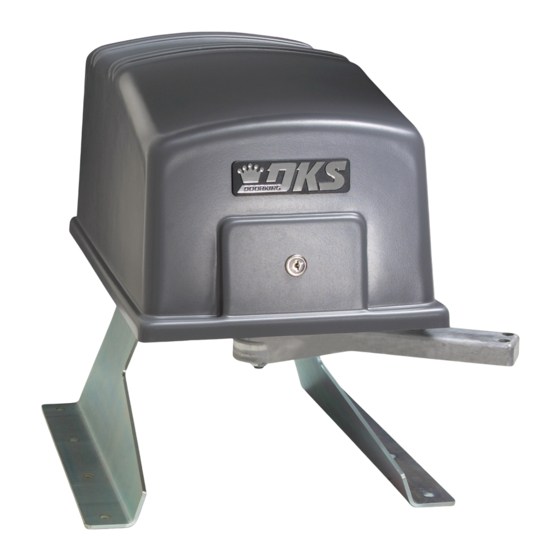
Installation/Owner's Manual
Use this manual for circuit board 4502-010 Revision K or higher.
For operators manufactured January 2016 and later.
P o
s t M
o u
n t
d M
P a
Date Installed:
Installer/Company Name:
Phone Number:
Leave Manual with Owner
UL 325 Compliant
n t
o u
Copyright 2016 DoorKing, Inc. All rights reserved.
Series 6050 and 6100
Series 6050 and 6100
Vehicular Swing Gate Operator
EXTERNAL ENTRAPMENT PROTECTION MUST be
installed or the gate operator WILL NOT function.
Circuit Board
Serial Number
and Revision Letter:
Copyright 2009 DoorKing, Inc. All rights reserved.
6050-065-C-2-16
Advertisement
Table of Contents
Troubleshooting

Subscribe to Our Youtube Channel
Related Manuals for DoorKing 6050-080


Summary of Contents for DoorKing 6050-080
- Page 1 WILL NOT function. s t M Date Installed: Installer/Company Name: Circuit Board Serial Number Phone Number: and Revision Letter: Leave Manual with Owner Copyright 2016 DoorKing, Inc. All rights reserved. UL 325 Compliant Copyright 2009 DoorKing, Inc. All rights reserved.
- Page 2 Auto-close timer is ON. Adjustable from 1-23 seconds to close gate. Not Used Leave in the OFF position. 3-Button OFF when using a 3-button station (DoorKing 3-button control stations only). Single Button ON when using a single button control, terminals 13 &14 become a STOP input. Dual Operators Switch must be OFF when bi-parting (dual) gates are used.
- Page 3 ON, an input to terminal #15 (e.g.: photo beam gets obstructed) has NO effect on the gate operator (Set for Shadow input). OPEN - DoorKing 3-Button station ONLY CLOSE - DoorKing 3-Button station ONLY Operation of the circuit board dry relay contact is dependent on setting of SW 1, switches 1 and 2.
- Page 4 2.25” DoorKing, Inc. reserves the right to make changes in the products described in this manual without notice and without obligation of DoorKing, Inc. to notify any persons of any such revisions or changes. Additionally, DoorKing, Inc. makes no representations or warranties with respect to this manual. This manual is copyrighted, all rights reserved.
-
Page 5: Table Of Contents
TABLE OF CONTENTS QUICK GUIDE - DIP-SWITCHES and MAIN TERMINAL Quick Guide-1 & 2 Previous Page SPECIFICATIONS ASTM F2200 Standard for Gate Construction Important Safety Instructions Instructions regarding intended installation: Important Notices UL 325 Entrapment Protection Glossary Swing Gate Requirements Swing Gate Protection SECTION 1 - INSTALLATION Operator Position... -
Page 6: Astm F2200 Standard For Gate Construction
ASTM F2200 Standard for Gate Construction Vehicular gates should be constructed and installed in accordance with ASTM F2200; Standard Specification for Automated Vehicular Gate Construction. For a copy of this standard, contact ASTM directly at 610-832-9585; service@astm.org; or www.astm.org. Important Safety Instructions WARNING - To reduce the risk of injury or death: 1. -
Page 7: Important Notices
• For gate operators utilizing contact sensors: 1. One or more contact sensors shall be located where the risk of entrapment or obstruction exist, such as at the leading edge, trailing edge, and post mounted both inside and outside of a vehicular horizontal slide gate. 2. -
Page 8: Ul 325 Entrapment Protection
UL 325 Entrapment Protection UL 325 Classifications Authoriz ed Personn el ONLY Class I - Residential Class III - Industrial/Limited Access Vehicular Gate Operator Vehicular Gate Operator A vehicular gate operator (or system) intended for use in garages A vehicular gate operator (or system) intended for use in an or parking areas associated with a residence of one-to four single industrial location or building such as a factory or loading dock families. -
Page 9: Glossary
Glossary GATE - A moving barrier such as a swinging, sliding, raising, lowering, or the like, barrier, that is a stand-alone passage barrier or is that portion of a wall or fence system that controls entrance and/or egress by persons or vehicles and completes the perimeter of a defined area. -
Page 10: Swing Gate Requirements
Swing Gate Requirements The operator is intended for installation only on gates used for vehicles. Pedestrians must be supplied with a separate access opening. The pedestrian access opening shall be designed to promote pedestrian usage. Locate the gate such that persons will not come in contact with the vehicular gate during the entire path of travel of the vehicular gate. -
Page 11: Swing Gate Protection
Swing Gate Protection Standard Non-contact Sensor Minimizes the potential of the gate closing on vehicular or other traffic Reverse Loop that loops cannot sense. Minimizes the potential of the gate closing when a vehicle is present. Warning Signs Number and placement of loops is Permanently mounted dependent on the application. -
Page 12: Section 1 - Installation
SECTION 1 - INSTALLATION Prior to beginning the installation of the swing gate operator, we suggest that you become familiar with the instructions, illustrations, and wiring guide-lines in this manual. This will help insure that your installation is performed in an efficient and professional manner compliant with UL 325 safety and ASTM F2200 construction standards. -
Page 13: Post Mount Or Pad Mount Base Assembly
1.2 Post Mount or Pad Mount Base Assembly (2) 1” bolts through the main gear bracket mounting holes. (2) 1 1/2” bolts through the main gear bracket mounting holes. Post Support Base Screw the posts to the support plate and mount into concrete BEFORE attaching the operator. -
Page 14: Underground Conduit Requirements
Use only sweeps for conduit bends. Do not use 90° elbows as this will make wire pulls very difficult Elbow and can cause damage to wire insulation. DoorKing recommends using 3/4-inch conduit. • Installation of External Entrapment Protection Devices is REQUIRED (photo sensor and/or reversing edge). -
Page 15: Post Mount
Note: 2” thick 1.5 Post Mount gate Illustrated. Mount the post base into the concrete 90° before installing the operator. Open Gate The post mount installation will allow the operator to be mounted low enough Concrete 6” 12” to attach the gate bracket to the lower Position gate rail if desired. -
Page 16: Manually Adjust The Open And Closed Gate Positions
The operator is now ready for AC power. 1.8 Installation of Warning Signs This DoorKing Swing Gate Operator is shipped with two warning signs. The purpose of the warning sign is to alert uninformed persons, and to remind persons familiar with the gate system, that a possible hazard exists so that appropriate action can be taken to avoid the hazard or to reduce exposure to the hazard. -
Page 17: Entrapment Protection Installation Required
1.9 Entrapment Protection Installation REQUIRED A monitored photo sensor (Type B1) or monitored reversing edge (Type B2, see next page) MUST be installed or operator WILL NOT function. A standard photo sensor can also be used as safety protection for the closing cycle of the gate, see below, but a monitored photo sensor or monitored reversing edge MUST also be installed. - Page 18 1.9 Continued A monitored reversing edge (Type B2) should be installed as entrapment protection for the closing cycle of the gate. Edge Transmitter OPTIONAL wireless transmitter can be used. Monitored Reversing Edge Typical Monitored Reversing Edge mounted on end of gate. Close-Direction Monitored Reversing Edge Mointored Sensor Note: Potential...
-
Page 19: Gates Opening Wider Than
1.10 Gates Opening Wider Than 90° The installation of an operator opening gates wider that 90° is the same for 1.3 through 1.8 except the operator and concrete pad will be in a different position. Individual requirements can be calculated following this 105° demonstrated sample. Gate Bracket Arm Assembly... -
Page 20: Section 2 - Ac Power To Operator(S)
SECTION 2 - AC POWER TO OPERATOR(S) Before attempting to connect any wiring to the operator, be sure that the circuit breaker in the electrical panel is in the OFF position. Permanent wiring must be installed to the operator as required by local electrical codes. It is recommended that a licensed electrical contractor perform this work. -
Page 21: Bi-Parting Gates Wiring - Dual Gate Operators
2.3 Bi-Parting Gates Wiring - Dual Gate Operators Connect the Primary/Secondary operators together with DoorKing’s interconnection cable as shown (Different lengths sold separately P/N 2600-75x). High voltage power and low voltage communications are supplied to the secondary operator by DoorKing’s UL approved cable Blue that is run in a single conduit. -
Page 22: Section 3 - Adjustments
Board Ground loop is activated. Tracker LEDs will flash as operator Secondary data is sent to the Operator Motor access controller Terminal (DoorKing models See page 17. 1833, 1835, 1837 Loop or 1838 only). EXIT LOOP Key Switch 9410 Single... -
Page 23: Dip-Switch Sw 1 & Sw2 Settings
Auto-close timer is ON. Adjustable from 1-23 seconds to close gate. Not Used Leave in the OFF position. 3-Button OFF when using a 3-button station (DoorKing 3-button control stations only). Single Button ON when using a single button control, terminals 13 &14 become a STOP input. Dual Operators Switch must be OFF when bi-parting (dual) gates are used. -
Page 24: Dip-Switch Descriptions
Switch 5 is NOT used. Leave in the OFF position. Switch 6 Sets up the circuit board for single button (ON setting) OR a DoorKing 3-button control station only (OFF setting). When this switch is ON, terminals 13 and 14 can be used as a Normally Open STOP input for single button control. When this switch is OFF, terminals 13 and 14 can be used with a DoorKing 3-Button control station ONLY for Open, Close and Stop input. -
Page 25: Automatic Open / Close Limit Adjustment
3.4 Automatic Open / Close Limit Adjustment The 6050/6100’s open/close limits DO NOT have to be physically adjusted. The gate open and close positions are determined by the physical stop “Flange” on the elbow assembly (See below). The arms MUST already be in the correct closed configuration (See Section 1.7 on page 11). -
Page 26: Clutch Adjustment
3.5 Clutch Adjustment This vehicular gate operator is equipped with an inherent adjustable clutch “Type C” that can be used as an entrapment protec- tion device. If the clutch is intended to be used as such, it must be adjusted to NOT open or close the gate with a sustained force greater than 40 lbs at the leading edge of the gate, except for the first 10 degrees of arc travel after any initiation of movement. -
Page 27: Section 4 - Wiring
ON, an input to terminal #15 (e.g.: photo beam gets obstructed) has NO effect on the gate operator (Set for Shadow input). OPEN - DoorKing 3-Button station ONLY CLOSE - DoorKing 3-Button station ONLY Operation of the circuit board dry relay contact is dependent on setting of SW 1, switches 1 and 2. -
Page 28: Control Wiring
EMS) may be placed at any location in the line-of-sight of the gate. 3-Wire Radio Receiver Limited to 250 ma. #11 - Access Control Devices 3-Button Station DoorKing ONLY Red Open Green Close White Com Telephone Entry Standard Reverse Photo Sensor ONLY... -
Page 29: Auxiliary Terminal Wiring
4.3 Auxiliary Terminal Wiring DoorKing Access Control System (Model 1833, 1835, 1837 or 1838) tracker system can be connected. This system can keep track of gate operator cycle count, shorted inputs, loop detector problems, any forced entry attempts, if the... -
Page 30: Loop Detector Wiring
DoorKing recommends that a DoorKing offers a free “Loop and licensed installer perform this work. -
Page 31: Section 5 - Operating Instructions
SECTION 5 - OPERATING INSTRUCTIONS IMPORTANT SAFETY INSTRUCTIONS WARNING - To reduce the risk of injury or death: 1. READ AND FOLLOW ALL INSTRUCTIONS. 2. Never let children operate or play with gate controls. Keep the remote control away from children. 3. -
Page 32: Shutdown Conditions
5.2 Shutdown Conditions Under various entrapment conditions the operator will assume either a soft or hard (alarm) shutdown. To determine what type of reset action is required, you will need to understand how the different entrapment conditions affect the gate operator. -
Page 33: Manual Gate Operation
Inspect the gate and gate hardware. Note: DoorKing operators have a built-in alarm reset push button mounted on the operator above the power ON-OFF toggle switch. Activating this button will return the gate operator to normal operation, but will not activate the gate operator. - Page 34 If the Gate Tracker reporting is in use, a forced entry attempt transaction will be sent to the DoorKing access control system at this time. Manual Release In addition to FAIL-SAFE manual operation, this operator also employs a locked release pin to place the gate in manual operation when AC power is removed.
-
Page 35: Section 6 - Maintenance And Troubleshooting
✓ Inspect for wear. Grease if necessary. Use only EP Molybdenum Gear ✓ Disulfide (Moly D) grease (DoorKing P/N 2600-770) Main shaft zert fitting. Grease ✓ Check that the gate reverses on contact with an object in both Inherent Reverse System the opening and closing cycles. -
Page 36: Troubleshooting
5. If a three-button control station (open-close-stop) is connected to this gate operator, check for proper wiring. Only a DoorKing three button control station (P/N 1200-006) can be used with this gate operator. Others will cause a malfunction. 6. Check the high voltage supply. A voltage drop on the supply line (usually caused by using too small supply voltage wires) will cause the operator to malfunction. - Page 37 Symptom Possible Solution(s) • Check that the clutch is adjusted properly and is not slipping. Gate opens a short • Disconnect the gate from the gate operator and check that the gate swings freely without any binding. distance, then stops •...
-
Page 38: Accessory Items
6.3 Accessory Items UL 325 Monitored Entrapment Protection Devices available for the model 6050 and 6100 swing gate operators. Type B2 Contact Sensors (Photo Cell) Miller Edge Sensing Edges - all models with a T2 (resistive) termination. Miller Edge Monitored Gate Link Model MGL-K20 Type B1 Non-contact Sensors (Reversing Edge) Miller Edge Reflective-Guard Model RG Miller Edge Prime-Guard Model PG... -
Page 39: Model 6050/6100'S Wiring Diagrams
Model 6050 / 6100 6050 1/2 HP - 4.3 amp 6050 30uf Capacitor 6100 1/2 HP - 5.4 amp 6100 50uf Capacitor Magnetic Blue Limit Sensor Blue White Ground Ground Board Ground Blue EXIT LOOP Yellow Brown 4502-010 KEY SWITCH DATA POWER SAFETY... - Page 40 Model 6050 / 6100 Secondary Operator Magnetic Limit Sensor 6050 1/2 HP - 4.3 amp 6100 1/2 HP - 5.4 amp 8. Gray Orange Orange 7. Orange Brown Brown 6. Brown Yellow Yellow 5. Yellow 4. Purple White White 3. White Blue Blue 2.
- Page 41 6050-065-C-2-16...
-
Page 42: 6050-065
Use this manual for circuit board 4502-010 Revision K or higher. 6050-065-C-2-16 For operators manufactured July 2011and later. www.doorking.com DoorKing, Inc. 120 S. Glasgow Avenue Inglewood, California 90301 U.S.A. Phone: 310-645-0023 Fax: 310-641-1586 Copyright 2009 DoorKing, Inc. All rights reserved.
Need help?
Do you have a question about the 6050-080 and is the answer not in the manual?
Questions and answers