Table of Contents
Advertisement
Quick Links
Installation/Owner's Manual
Use this manual for circuit board 4502-010 Revision AA or higher.
Entrapment Protection must be provided for the gate system where the risk of entrapment or obstruction exists.
The operator will not run without one or more monitored type B1 or B2 entrapment protection devices.
P o
s t M
o u
W A
P a
R N
IN
G
M OV
SE
IN
RI
OU
G
GA
Ope
S IN
TE
and
rate
JU
CA
free
gat
e onl
RY
N
CA
Do
of
peo
y wh
OR
US
or
not
allo
ple
en
DE
E
ope
rate
chi
w
and
obs
gat
e are
AT
H
Do
not
gat
e.
ldre
truc
a is
h wh
pat
sta
n to
pla
tion
s.
in
sig
ile
nd
in
y in
ht
Rea
d ow
gat
gat
e is
e pat
gat
e are
CO
NF
ner
mo
vin
h or
a
AN
SI/
OR
MS
's
ma
g.
wal
k thro
UL
-32
TO
nua
l and
ugh
CA
N/C
CE
RT
5
saf
SA
IFI
ED
ety
ins
VE
HI
C2
2.2
TO
truc
tion
CU
NO
s.
CL
AS
LA
R
. 247
533
82
S
GA
TE
MO
OP
DE
L
ER
SE
HP
AT
OR
RIA
L
VO
LTS
AM
PS
MA
X GA
PH
TE
AS
E
Do
LO
AD
60
orK
ing
Hz
, Inc
.,
Ing
lew
ood
, CA
THIS PRODUCT IS TO BE INSTALLED AND SERVICED BY A TRAINED GATE SYSTEMS TECHNICIAN ONLY.
Visit www.dkslocator.com to find a professional installing and servicing dealer in your area.
Date Installed:
Installer/Company Name:
Phone Number:
Leave Manual with Owner
Conforms To UL STD 325
Certified To CSA STD C22.2 # 247
n t
n t
o u
d M
Copyright 2018 DoorKing, Inc. All rights reserved.
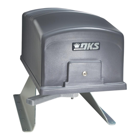
Vehicular Swing Gate Operator
Circuit Board
Serial Number
and Revision Letter:
Copyright 2009 DoorKing, Inc. All rights reserved.
Series 6300
Series 6300
6300-065-R-5-18
Convenience Open Optional
Advertisement
Table of Contents
Troubleshooting

Related Manuals for DoorKing 6300 Series


Summary of Contents for DoorKing 6300 Series
- Page 1 Installer/Company Name: Circuit Board Serial Number Phone Number: and Revision Letter: Leave Manual with Owner Copyright 2018 DoorKing, Inc. All rights reserved. Conforms To UL STD 325 Certified To CSA STD C22.2 # 247 Copyright 2009 DoorKing, Inc. All rights reserved.
- Page 2 Swing Operator Normal Setting. Switch must be ON for swing gate operator. 3-Button OFF when using a 3-button station (DoorKing 3-button control stations only). Single Button ON when using a single button control, terminals 13 &14 become a STOP input.
- Page 3 ON, an input to terminal #15 has NO effect on the gate operator (Set for Full Open/Open Loop Shadow input). OPEN - DoorKing 3-Button station ONLY CLOSE - DoorKing 3-Button station ONLY SW 4 Operation of the circuit board dry relay contact is dependent on setting of SW 4, switches 1 and 2.
-
Page 4: Specifications
10” DoorKing, Inc. reserves the right to make changes in the products described in this manual without notice and without obligation of DoorKing, Inc. to notify any persons of any such revisions or changes. Additionally, DoorKing, Inc. makes no representations or warranties with respect to this manual. This manual is copyrighted, all rights reserved. -
Page 5: Table Of Contents
TABLE OF CONTENTS QUICK GUIDE - DIP-SWITCHES and MAIN TERMINAL Quick Guide-1 & 2 Previous Page SPECIFICATIONS Swing Gate Requirements Swing Gate Protection ASTM F2200 Standard for Gate Construction Important Safety Instructions Instructions regarding intended installation: Important Notices UL 325 Entrapment Protection Glossary SECTION 1 - INSTALLATION Operator Position... -
Page 6: Swing Gate Requirements
Swing Gate Requirements The operator is intended for installation only on gates used for vehicles. Pedestrians must be supplied with a separate access opening. The pedestrian access opening shall be designed to promote pedestrian usage. Locate the gate such that persons will not come in contact with the vehicular gate during the entire path of travel of the vehicular gate. -
Page 7: Swing Gate Protection
Swing Gate Protection Non-contact Sensor Minimizes the potential of the gate closing on vehicular or other traffic that loops cannot sense. Monitored device helps protect against entrapment when needed. Reverse Loop Minimizes the potential of the gate Warning Signs closing when a vehicle is present. Permanently mounted and Number and placement of loops is Moving Gate Can Cause... -
Page 8: Astm F2200 Standard For Gate Construction
ASTM F2200 Standard for Gate Construction Vehicular gates should be constructed and installed in accordance with ASTM F2200; Standard Specification for Automated Vehicular Gate Construction. For a copy of this standard, contact ASTM directly at 610-832-9585; service@astm.org; or www.astm.org. Important Safety Instructions WARNING - To reduce the risk of injury or death: 1. -
Page 9: Important Notices
Important Notices Vehicular gate operator products provide convenience and security. However, gate operators must use high levels of force to move gates and most people underestimate the power of these systems and do not realize the potential hazards associated with an incorrectly designed or installed system. These hazards may include: •... -
Page 10: Ul 325 Entrapment Protection
UL 325 Entrapment Protection UL 325 Classifications Authoriz ed Personn el ONLY Class I - Residential Class III - Industrial/Limited Access Vehicular Gate Operator Vehicular Gate Operator A vehicular gate operator (or system) intended for use in garages A vehicular gate operator (or system) intended for use in an or parking areas associated with a residence of one-to four single industrial location or building such as a factory or loading dock families. -
Page 11: Glossary
Glossary GATE - A moving barrier such as a swinging, sliding, raising, lowering, or the like, barrier, that is a stand-alone passage barrier or is that portion of a wall or fence system that controls entrance and/or egress by persons or vehicles and completes the perimeter of a defined area. -
Page 12: Section 1 - Installation
SECTION 1 - INSTALLATION Prior to beginning the installation of the swing gate operator, we suggest that you become familiar with the instructions, illustrations, and wiring guide-lines in this manual. This will help insure that your installation is performed in an efficient and professional manner compliant with UL 325 safety and ASTM F2200 construction standards. -
Page 13: Post Mount Or Pad Mount Base Assembly
1.2 Post Mount or Pad Mount Base Assembly 1 1/2” bolts through the main gear bracket mounting holes. Hardware for Post Mount: Post Support Base (6) 1 1/2 inch bolts. For support plate. Screw the posts to the support (4) Non-slip nuts. For existing plate and mount into concrete threaded studs on bottom of 6300. -
Page 14: Underground Conduit Requirements
Use only sweeps for conduit bends. Do not use 90° elbows as this will make wire pulls very difficult Elbow and can cause damage to wire insulation. DoorKing recommends using 3/4-inch conduit. • Installation of External Entrapment Protection Devices is REQUIRED (photo sensor and/or reversing edge). -
Page 15: Post Mount
1.5 Post Mount Note: 2” thick Important Note: These post mount measurements will gate Illustrated. ONLY work when the operator is positioned using the “1.1 Operator Position” measurements on page 8. Mount the post base into the concrete 90° before installing the operator. Open Gate The post mount installation will allow Concrete... -
Page 16: Manually Adjust The Open And Closed Gate Positions
The operator is now ready for AC power. 1.8 Installation of Warning Signs This DoorKing Swing Gate Operator is shipped with two warning signs. The purpose of the warning sign is to alert uninformed persons, and to remind persons familiar with the gate system, that a possible hazard exists so that appropriate action can be taken to avoid the hazard or to reduce exposure to the hazard. -
Page 17: Entrapment Protection Installation Required
1.9 Entrapment Protection Installation REQUIRED External Entrapment Protection Devices: In addition to the inherent reversing sensor system, this operator has a UL 325 terminal for the connection of photo sensors-Type B1 and/or reversing edges-Type B2 entrapment protection required by UL 325 standards. Entrapment Protection must be provided for the gate system where the risk of entrapment or obstruction exists. - Page 18 1.9 Continued A monitored reversing edge (Type B2) or a monitored photo sensor (Type B1, see previous page) MUST be installed or operator WILL NOT function. Edge Transmitter OPTIONAL wireless transmitter can be used. Monitored Reversing Edge Typical Monitored Reversing Edge mounted on end of gate. Reversing Edge Mointored Sensor Note: Potential...
-
Page 19: Gates Opening Wider Than
1.10 Gates Opening Wider Than 90° The installation of an operator opening gates wider that 90° is the same for sections 1.3 through 1.9 except the operator and concrete pad will be in a different position. Individual requirements can be calculated following this 105° opening sample. Arm Assembly Connecting arm’s pivot point measurement 62.25”... -
Page 20: Overlapping Bi-Parting Gate Operator Positions
1.11 Overlapping Bi-Parting Gate Operator Positions When installing overlapping gates (using a maglock to secure gates in the center or architectural overlapping design etc.), certain considerations must be taken into account or gates will NOT operate correctly. The SECONDARY operator OPENS 1-2 secs BEFORE the primary operator (SW3, switch 6 - ON) to allow the secondary operator’s gate to stay clear of the gate overlap. -
Page 21: Section 2 - Ac Power To Operator(S)
SECTION 2 - AC POWER TO OPERATOR(S) Before attempting to connect any wiring to the operator, be sure that the circuit breaker in the electrical panel is in the OFF position. Permanent wiring must be installed to the operator as required by local electrical codes. It is recommended that a licensed electrical contractor perform this work. -
Page 22: Bi-Parting Gates Wiring - Dual Gate Operators
Connect the Primary/Secondary operators together with DoorKing’s interconnection cable as shown (Different lengths sold separately P/N 2600-75x). High voltage power and low voltage communications are supplied to the secondary operator by DoorKing’s UL approved cable that is run in a single conduit. Two conduits (High voltage and low voltage) will need to be provided to the secondary operator when NOT using DoorKing’s UL listed, wet environment interconnec-... -
Page 23: Section 3 - Adjustments
Board Ground loop is activated. Tracker LEDs will flash as operator Secondary data is sent to the Operator Motor access controller Terminal (DoorKing models See page 18. 1833, 1835, 1837 Loop or 1838 only). EXIT LOOP Key Switch 9410 Single... -
Page 24: Dip-Switch Sw 3 & Sw 4 Settings
Swing Operator Normal Setting. Switch must be ON for swing gate operator. 3-Button OFF when using a 3-button station (DoorKing 3-button control stations only). Single Button ON when using a single button control, terminals 13 &14 become a STOP input. -
Page 25: Dip-Switch Definitions
Switch 6 Sets up the circuit board for single button (ON setting) OR a DoorKing 3-button control station only (OFF setting). When this switch is ON, terminals 13 and 14 can be used as a Normally Open STOP input for single button control. When this switch is OFF, terminals 13 and 14 can be used with a DoorKing 3-Button control station ONLY for Open, Close and Stop input. -
Page 26: Automatic Open / Close Limit Adjustment
3.4 Automatic Open / Close Limit Adjustment The 6300’s open/close limits DO NOT have to be physically adjusted. The gate open and close positions are determined by the physical stop “Flange” on the elbow assembly (See below). The arms MUST already be in the correct closed configuration (See Section 1.7 on page 12). -
Page 27: Clutch Adjustment
3.5 Clutch Adjustment This vehicular gate operator is equipped with an inherent adjustable clutch. The clutch MUST slip upon sensing an obstruction during the open or close cycle which will cause the gate to reverse direction. For this system to function correctly, the gate must be properly installed and work freely in both directions. A good set of roller bearing hinges is essential for proper swing gate operation. -
Page 28: Section 4 - Wiring
ON, an input to terminal #15 has NO Full Open/Open Loop effect on the gate operator (Set for Shadow input). OPEN - DoorKing 3-Button station ONLY CLOSE - DoorKing 3-Button station ONLY SW 4 Operation of the circuit board dry relay contact is dependent on setting of SW 4, switches 1 and 2. -
Page 29: Control Wiring
Exceeding 250 mA of power from this terminal may cause the circuit board transformer to overheat, causing intermittent problems. Key Switch 3-Button Control Station 24 VAC Red Open Green Close DoorKing ONLY P/N 1200-006 Stand-Alone White Com Keypad Access Device Open... -
Page 30: Auxiliary Terminal Wiring
4.3 Auxiliary Terminal Wiring DoorKing Access Control System (Model 1833, 1835, 1837 or 1838) tracker system can be connected. This system can keep track of gate operator cycle count, shorted inputs, loop detector problems, any forced entry attempts, if the... -
Page 31: Loop Detector Wiring
• Loop layout shown is for a typical swing gate when it is in the gate’s path. DoorKing recommends that a application with two-way traffic, or one-way exit licensed installer perform this work. -
Page 32: Section 5 - Operating Instructions
SECTION 5 - OPERATING INSTRUCTIONS IMPORTANT SAFETY INSTRUCTIONS WARNING - To reduce the risk of injury or death: 1. READ AND FOLLOW ALL INSTRUCTIONS. 2. Never let children operate or play with gate controls. Keep the remote control away from children. 3. -
Page 33: Shutdown Conditions
5.2 Shutdown Conditions Under various entrapment conditions the operator will assume either a soft or hard (alarm) shutdown. To determine what type of reset action is required, you will need to understand how the different entrapment conditions affect the gate operator. -
Page 34: Manual Gate Operation
Note: DoorKing operators have a built-in alarm reset push button mounted on the operator above the power ON-OFF toggle switch. Activating this button will return the gate operator to normal operation, but will not activate the gate operator. - Page 35 If the Gate Tracker reporting is in use, a forced entry attempt transaction will be sent to the DoorKing access control system at this time. Manual Release In addition to FAIL-SAFE manual operation, this operator also employs a locked release pin to place the gate in manual operation when primary (AC) power is removed.
-
Page 36: Section 6 - Optional Convenience Open
100% power backup and continuous operation when primary (AC) power has failed, a power inverter / backup system, such as DoorKing’s Model 1000 can be installed (Sold separately). Be sure your installation is in compliance with local codes. •... -
Page 37: Section 7 - Maintenance And Troubleshooting
Inspect for damage. Check gate hinges for wear and grease if necessary. ✓ Inspect for wear. Grease if necessary. Use only EP Molybdenum Gear ✓ Disulfide (Moly D) grease (DoorKing P/N 2600-770) Main shaft zert fitting. Grease ✓ Check that the gate reverses on contact with an object in both the opening and closing cycles. -
Page 38: Troubleshooting
If the gate operator starts, this indicates that a problem exist with the keying device and is not with the gate operator. 5. If a three-button control station (open-close-stop) is connected to this gate operator, check for proper wiring. Only a DoorKing three button control station (P/N 1200-006) can be used with this gate operator. Others will cause a malfunc- tion. - Page 39 Symptom Possible Solution(s) Operator will not run, entrapment protection • The entrapment protection device has a fault or the wiring to it is shorted. input(s) LED is ON. Operator will not run, entrapment protection • The entrapment protection device is not connected or the wiring to it is open. input(s) LED is Blinking.
-
Page 40: Accessory Items
7.3 Accessory Items UL 325 Monitored Entrapment Protection Devices available for the model 6300 swing gate operator. Type B2 Contact Sensors (Reversing Edge) Miller Edge Sensing Edges - all models with a T2 (resistive) termination. Miller Edge Monitored Gate Link Model MGL-K20 Miller Edge wireless monitored transmitter/receiver kit model RB-G-K10 ASO GMBH Sentir GF Series sensing edges Type B1 Non-contact Sensors (Photo Cell) -
Page 41: Model 6300'S Wiring Diagrams
Model 6300 1/2 HP 115 VAC 1/2 HP 50uf Capacitor Magnetic Blue Limit Sensor Blue White Ground Ground SECONDARY OPERATOR MOTOR Blue EXIT LOOP Yellow Brown 4502-010 KEY SWITCH DATA POWER SW 4 SAFETY SW 3 LOOP Orange White White Yellow White Black... - Page 42 Model 6300 1/2 HP 115 VAC / Convenience Open (2380) 1/2 HP Batteries 50uf Capacitor Magnetic Blue Limit Sensor Blue White Ground Ground SECONDARY White OPERATOR MOTOR Blue Blue Purple Black/White White Red/White Green EXIT LOOP Yellow Brown 4502-010 KEY SWITCH DATA 2380-010 POWER...
- Page 43 Model 6300 1 HP 115 VAC 1 HP Magnetic Limit Sensor Blue White Ground Ground SECONDARY OPERATOR MOTOR Blue EXIT LOOP Yellow Brown 4502-010 KEY SWITCH DATA POWER SW 4 SAFETY SW 3 LOOP Orange White White Yellow White Black Convenience Outlets Chassis Ground...
- Page 44 Model 6300 1 HP 115 VAC / Convenience Open (2380) 1 HP Batteries Magnetic Limit Sensor Blue White Ground Ground SECONDARY White OPERATOR MOTOR Blue Blue Purple Black/White White Red/White Green EXIT LOOP Yellow Brown 4502-010 KEY SWITCH DATA 2380-010 POWER SW 4 See page 32 for 2380 convenience...
- Page 45 Model 6300 1/2 HP Secondary Operator See page 18 for Primary/Secondary Magnetic operators interconnection information. Limit Sensor 8. Gray 1/2 HP Orange 7. Orange Brown 6. Brown Yellow 5. Yellow 4. Purple White White 3. White Blue Blue 2. Blue Ground 1.
- Page 46 Model 6300 1 HP Secondary Operator See page 18 for Primary/Secondary Magnetic operators interconnection information. Limit Sensor 8. Gray Orange 7. Orange 1 HP Brown 6. Brown Yellow 5. Yellow 4. Purple White White 3. White Blue Blue 2. Blue 1.
-
Page 47: Section 8 - Owner Of The Gate Operator
SECTION 8 - OWNER OF THE GATE OPERATOR 8.1 Alarm Sounding and Gate WILL NOT Operate A KEY has been supplied that will Note: The owner of the gate operator is responsible for unlock the power switch cover on the KEY availability. this gate operator. -
Page 48: Manual Gate Operation
Note: If the Gate Tamper Protect is in use, a forced entry attempt transaction will be sent to the DoorKing access control system at this time. Manual Release In addition to FAIL-SAFE manual operation, this operator also employs a locked release pin to place the gate in manual operation when (AC) power is removed. -
Page 49: Gate Operators Monthly Checkup
If you feel uncomfortable performing any of these inspections or testing, a qualified service technician will perform the visual inspections and testing for you. You can find a trained service technician at DoorKing’s “Dealer Locator” at www.doorking.com Visual Inspection Visually inspect the rollers, fasteners, brackets and other gate hardware for proper alignment, proper tightness, and signs of damage, breakage, looseness, rust or wear. - Page 50 This page intentionally left blank. 6300-065-R-5-18...
- Page 52 THIS PRODUCT IS TO BE INSTALLED AND SERVICED BY A TRAINED GATE SYSTEMS TECHNICIAN ONLY. Visit www.dkslocator.com to find a professional installing and servicing dealer in your area. www.doorking.com DoorKing, Inc. 120 S. Glasgow Avenue Inglewood, California 90301 U.S.A. Phone: 310-645-0023 Fax: 310-641-1586 Copyright 2009 DoorKing, Inc. All rights reserved.
Need help?
Do you have a question about the 6300 Series and is the answer not in the manual?
Questions and answers