Table of Contents
Advertisement
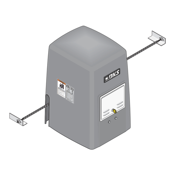
Installation/Owner's Manual
Use this manual for circuit board 4405-010 Revision D or higher.
Date Installed:
Installer/Company Name:
Phone Number:
Leave Manual with Owner
UL 325 Compliant
Circuit Board
Serial Number
and Revision Letter:
Copyright 2011 DoorKing, Inc. All rights reserved.
Series 9000
Series 9000
Series 9000
Vehicular Slide Gate Operator
Copyright 2009 DoorKing, Inc. All rights reserved.
9000-065-J-9-11
TM
Advertisement
Table of Contents
Troubleshooting

Related Manuals for DoorKing 9000-080


Summary of Contents for DoorKing 9000-080
- Page 1 Use this manual for circuit board 4405-010 Revision D or higher. 9000-065-J-9-11 Date Installed: Installer/Company Name: Circuit Board Serial Number Phone Number: and Revision Letter: Leave Manual with Owner Copyright 2011 DoorKing, Inc. All rights reserved. UL 325 Compliant Copyright 2009 DoorKing, Inc. All rights reserved.
-
Page 3: Specifications
Concrete Pad DoorKing, Inc. reserves the right to make changes in the products described in this manual without notice and without obligation of DoorKing, Inc. to notify any persons of any such revisions or changes. Additionally, DoorKing, Inc. makes no representations or warranties with respect to this manual. This manual is copyrighted, all rights reserved. No portion of this manual may be copied, reproduced, translated, or reduced to any electronic medium without prior written consent from DoorKing, Inc. -
Page 4: Table Of Contents
1.6 Positioning Operator and Chain 1.7 Attaching Operator and Chain 1.8 Endless Idler Assembly On Select Installations 1.9 DoorKing’s Chain Tray Kit 1.10 Installation of Warning Signs SECTION 2 - AC POWER TO OPERATOR(S) 2.1 AC Power Wire Runs and Terminal Connection 2.2 Bi-Parting Gates Wiring - Dual Gate Operators... - Page 5 TABLE OF CONTENTS SECTION 3 - ADJUSTMENTS 3.1 4405 Circuit Board Descriptions and Adjustments 3.2 DIP-Switch Settings for 4405 Circuit Board 22-23 3.3 Limit Switches 3.4 Inherent Reverse Sensor Adjustment 3.5 Secondary Current Sensor Adjustment (Dual Gates) SECTION 4 - ENTRAPMENT AND SAFETY PROTECTION 4.1 UL 325 Terminal Wiring 4.2 Secondary Entrapment Protection Device Locations 28-29...
-
Page 6: Astm 2200 Standard For Gate Construction
ASTM F2200 Standard for Gate Construction Vehicular gates should be constructed and installed in accordance with ASTM F2200; Standard Specification for Automated Vehicular Gate Construction. For a copy of this standard, contact ASTM directly at 610-832-9585; service@astm.org; or www.astm.org. Important Safety Instructions WARNING - To reduce the risk of injury or death: 1. -
Page 7: Important Notices
• For gate operators utilizing contact sensors: 1. One or more contact sensors shall be located where the risk of entrapment or obstruction exist, such as at the leading edge, trailing edge, and post mounted both inside and outside of a vehicular horizontal slide gate. 2. -
Page 8: Ul325 Entrapment Protection
UL 325 Entrapment Protection Class I Class II A vehicular gate operator (or system) intended for use in a A vehicular gate operator (or system) intended for use in a home of one-to four single family dwelling, or a garage or commercial location or building such as a multi-family parking area associated therewith. -
Page 9: Glossary
Glossary GATE - A moving barrier such as a swinging, sliding, raising, lowering, or the like, barrier, that is a stand-alone passage barrier or is that portion of a wall or fence system that controls entrance and/or egress by persons or vehicles and completes the perimeter of a defined area. -
Page 10: Slide Gate Requirements
Slide Gate Requirements The operator is intended for installation only on gates used for vehicles. Pedestrians must be supplied with a separate access opening. The pedestrian access opening shall be designed to promote pedestrian usage. Locate the gate such that persons will not come in contact with the vehicular gate during the entire path of travel of the vehicular gate. -
Page 11: Slide Gate Protection
Slide Gate Protection Entrapment protection devices are required to reduce the risk of injury. Install sensors where the risk of entrapment or obstruction exists while gate is moving. Individual requirements will vary. Contact Sensor (Reversing Edges) Warning Signs Installed on the fence to help minimize the potential of Permanently mounted entrapment between the gate and fence. -
Page 12: Section 1 - Installation
1.1 Hardware for the Gate Good hardware is essential for proper operation of a sliding gate. DoorKing has a full line of gate hardware products that will ensure safe, reliable and long lasting gate operation. The gate must be properly installed and roll smoothly in both directions. -
Page 13: Gate Types
1.3 Typical Gate Types The Model 9000 operator is designed to be installed on any of these gate types. See the next 3 pages for specific operator mounting positions. • Steel or Aluminum. • 1,500 lb max. weight per gate (1 HP motor). •... -
Page 14: Operator Mounting Positions
1.4 Operator Mounting Positions The Model 9000 operator is designed to be installed in the front, rear and center mounting positions shown on this page and the next 2 pages. V-wheel V-rail ornamental gates are shown as examples but other gate types on the previous page can use the same mounting setups. - Page 15 Rear Position with Concrete Pad Idler Wheels and Chain Setup Hides the chain from outside the property looking in. • Set one chain Idler wheel at the top and one in the center position. A filler post or barrier may need to be installed between Top View the gate and wall area (See page 8 for more information).
- Page 16 Center Position with Post Mount Kit Hides the chain from outside the property looking in. Allows the use of DoorKing’s chain tray kit to attach to gate. This is useful with long gates. It supports the chain’s weight and helps prevent chain “stretching”.
-
Page 17: Concrete Pad Setup Or Optional Post Mount Kit
(Work Area) Top View Side View Optional Post Mount Kit Base Plate DoorKing offers a post mount kit specifically for the Model 9000 (P/N 9000-015). The kit Wall includes a base plate, 2 posts and hardware to Operator attach the operator to the base plate. This kit 4”... -
Page 18: Positioning Operator And Chain
Attaching Operator t i o to Gate. Weld completely to Concrete Pad around bracket. Chain nut DoorKing recommends a Chain and chain bolt should not minimum of four (4) 3/8” x 2” protrude past gate frame. sleeve anchors (not supplied). -
Page 19: Endless Idler Assembly ( On Select Installations )
On Select Installations DoorKing offers an endless idler assembly with a protective cover designed for the Model 9000 installations (P/N 2600-818). Make sure the endless idler assembly is securely fastened to the wall or post (Depending on which type of installation will be used). -
Page 20: Doorking's Chain Tray Kit
1.9 DoorKing’s Chain Tray Kit A chain tray is recommended for gates longer than 20 ft. to support the weight of the chain. DoorKing offers a chain tray kit in 10 ft. sections to fit any length gate. (DoorKing P/N 2601-270 10 Ft. section) -
Page 21: Section 2 - Ac Power To Operator(S)
SECTION 2 - AC POWER TO OPERATOR(S) Before attempting to connect any wiring to the operator, be sure that the circuit breaker in the electrical panel is in the OFF position. Permanent wiring must be installed to the operator as required by local electrical codes. It is recommended that a licensed electrical contractor perform this work. -
Page 22: Bi-Parting Gates Wiring - Dual Gate Operators
Connect the Primary/Secondary operators together with DoorKing’s interconnection cable (P/N 2600-75x) as shown. High voltage power and low voltage communications are supplied to the secondary operator by DoorKing’s UL approved cable that is run in a single conduit. Two conduits (High voltage and low voltage) will need to be provided to the secondary operator when NOT using DoorKing’s UL listed, wet environment interconnection cable. -
Page 23: Section 3 - Adjustments
SECTION 3 - ADJUSTMENTS The switch settings and adjustments in this chapter should be made after your installation and wiring to the operator(s) is complete. Whenever any of the programming DIP-switches on the circuit board are changed, power must be shut-off, and then turned back on for the new setting to take effect. -
Page 24: Dip-Switch Settings For 4405 Circuit Board
3.2 DIP-Switch Settings for 4405 Circuit Board The two DIP-switches located on the circuit board are used to program the operator to operate in various modes and to turn on or off various operating features. Whenever a switch setting is changed, power to the operator must be turned OFF and then turned back on for the new setting to take affect. - Page 25 3.2 Continued Switch Definitions SW 1 (Top 8 Switches) Typical Settings Must OPEN the primary operator’s gate upon initial AC power up and open command. If the first open command Switch 1 begins to close the gate, turn AC power off and reverse this switch. Must OPEN the secondary operator’s gate upon initial AC power up and open command.
-
Page 26: Limit Switches
3.3 Limit Switches Full Open and Close Limits MUST be Set The operator normally stops a cycling gate using the open and close limits. If the limits have not been set, the gate could continue beyond its full open and close positions, damaging the gate and operator. -
Page 27: Inherent Reverse Sensor Adjustment
3.4 Inherent Reverse Sensors Adjustment This vehicular gate operator is equipped with an inherent adjustable reversing sensor (Type A) used as the primary entrapment protection system according to UL 325 standards. The gate will reverse direction after “physically” encountering an obstruction in either the opening or closing gate cycle. -
Page 28: Secondary Current Sensor Adjustment (Dual Gates)
3.5 Secondary Current Sensor Adjustment (Dual Gates ONLY) The PRIMARY gate operator’s “secondary reversing sensor” uses a secondary current sensing device (Located only in the primary operator) to detect any obstructions “physically” encountered in the SECONDARY gate path when using dual gates. The secondary current sensor uses a sensing coil with a given number of turns through it to monitor the current flow into the secondary operator. -
Page 29: Section 4 - Entrapment And Safety Protection
SECTION 4 - ENTRAPMENT AND SAFETY PROTECTION Secondary Entrapment Protection Devices: In addition to the inherent reversing sensor system, the Model 9000 has a 6-pin UL 325 terminal for the connection of photo sensors-Type B1 and reversing edges-Type B2 secondary entrapment protection devices required by UL 325 standards. Entrapment protection devices must be installed to reduce the risk of injury. -
Page 30: Secondary Entrapment Protection Device Locations
4.2 Secondary Entrapment Protection Device Locations Typical UL Photo Sensor mounting height If the distance between the gate and distance away from gate. and wall is greater than 2 1/4”. Filler Post or Barrier Non-Secure Side Secure Side Outside Property Inside Property 5”... - Page 31 Wireless Reverse Edge Sample Setup - Single Receiver Edge Normally Open 9 V battery operated transmitter mounted on gate. Transmitter Filler Post Note: Install reversing edges on all Normally Open the gate support posts or filler post in this area (e.g.
-
Page 32: Loop Detectors
A loop detection system will sense a vehicle like a metal detector and send a signal to the gate operator preventing the gate from automatically opening or closing on a vehicle when it is in the gate’s path. DoorKing recommends that a licensed installer perform this work. -
Page 33: Section 5 - Main Terminal Wiring
Entrapment Alarm 1 amp maximum SW 1 at 24-volts DC. Alarm Reset Secondary Current Sensor DoorKing’s Remote alarm reset station can be connected. See Motor next page for wiring. It MUST be mounted in the Motor line-of-sight of the gate operator. -
Page 34: Control Wiring
For more 20-Pin Main detailed information refer to the Tracker Installation and Wiring Manual, DoorKing P/N 2351-010. Terminal... -
Page 35: Section 6 - Operating Instructions
SECTION 6 - OPERATING INSTRUCTIONS IMPORTANT SAFETY INSTRUCTIONS WARNING - To reduce the risk of injury or death: 1. READ AND FOLLOW ALL INSTRUCTIONS. 2. Never let children operate or play with gate controls. Keep the remote control away from children. 3. -
Page 36: Shutdown Conditions
Activation of a close command will run the gate to the closed position. Note: DoorKing operators have a built-in alarm reset push button mounted on the operator (See previous page for reset button location). -
Page 37: Manual Gate Operation
6.3 Manual Gate Operation Caution: Never attempt to manually operate any gate until you have verified that power to the operator has been shut-off. Pull Manual Release Handle Pull straight OUT as far as possible and then UP. Release Handle With handle in UP position, slide back down to lock it in manual release position. -
Page 38: Section 7 - Maintenance And Troubleshooting
SECTION 7 - MAINTENANCE AND TROUBLESHOOTING Inspection and service of this gate operator by a qualified technician should be performed anytime a malfunction is observed or suspected. High cycle usage may require more frequent service checks. 7.1 Maintenance When servicing the gate operator, always check any secondary (external) reversing devices (loops, photocells, etc.) for proper operation. If external reversing devices cannot be made operable, do not place this operator in service until the malfunction can be identified and corrected. -
Page 39: Troubleshooting
For more information on trouble shooting loops and loop detectors, refer to your loop detector instruction sheet and to the DoorKing Loop and Loop Detector Information Manual. 4. Check to be sure that there are no shorted or open control wires from the keying devices to the gate operator. If a keying device fails to open the gate, momentarily jumper across terminals 1 and 2 (or 1 and 5) on the gate operator circuit board. - Page 40 Symptom Possible Solution(s) Secondary operator • Check that SW-1, switch 6 is ON. motor will not run. • Press secondary operator motor reset button firmly. • Remove circuit board. Momentarily jumper terminal 19 to the primary/secondary interconnection cable terminal 1, then to terminal 2 with a 14 AWG insulated jumper wire. CAUTION –...
-
Page 41: Accessory Items
7.4 Accessory Items The following accessory items are available for the model 9000 slide gate operator. Contact Sensors - For use as a secondary entrapment protection device. Miller Edge, Inc., MGO20, MGR20, MGS20 Photo Cell - Non-contact (photocell) sensors for use as a secondary entrapment protection device. MMTC, Inc. -
Page 42: Model 9000 115 Vac Wiring Diagram
Model 9000 1/2 HP or 1 HP 115 VAC Single Phase Remote Radio Secondary Interface Receiver Terminal Limit Switch Partial Limit Switch Terminal Open White Sensor Gray Gray Brown Yellow Orange Orange Chassis Ground White Orange Yellow Brown Blue Gray Orange White Brown... - Page 43 9000-065-J-9-11...
-
Page 44: 9000-065
Series 9000 Installation/Owner’s Manual Vehicular Slide Gate Operator Use this manual for circuit board 4405-010 Revision D or higher. 9000-065-J-9-11 www.doorking.com DoorKing, Inc. 120 Glasgow Avenue Inglewood, California 90301 U.S.A. Phone: 310-645-0023 Fax: 310-641-1586 Copyright 2009 DoorKing, Inc. All rights reserved.
Need help?
Do you have a question about the 9000-080 and is the answer not in the manual?
Questions and answers