Table of Contents
Advertisement
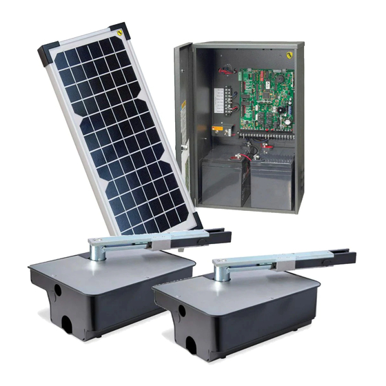
Wiring / Owner's
Manual
Use this manual for circuit board 4302-010 Revision N or higher.
EXTERNAL ENTRAPMENT PROTECTION
MUST be installed or the gate operator
WILL NOT function.
6 4
0 0
Date Installed:
Installer/Company Name:
Phone Number:
Leave Manual with Owner
UL 325 Compliant
Solar Control Box for
Solar Control Box for
Solar Control Box for
6002, 6003, 6004 and 6400 gate operators
2 4
2 4
V o
V o
1 0
1 0
l t
l t
W
W
a t
a t
S o
S o
t
t
l a
l a
P a
P a
r
r
n e
n e
l
l
6 0
0 3
Copyright 2016 DoorKing, Inc. All rights reserved.
2 4
2 4
V o
V o
2 0
2 0
l t
l t
W
W
S o
S o
a t
a t
t
t
l a
l a
P a
P a
r
r
n e
n e
l
l
6 0
0 2
D
O
O
R
K
I
N
G
Circuit Board
Serial Number
and Revision Letter:
Copyright 2009 DoorKing, Inc. All rights reserved.
4302-067-N-1-16
S o
l a
C o
r
n t
r o
B o
l
x
6 0
0 4
Advertisement
Table of Contents
Troubleshooting

Related Manuals for DoorKing 6002


Summary of Contents for DoorKing 6002
- Page 1 Solar Control Box for Solar Control Box for Solar Control Box for Manual 6002, 6003, 6004 and 6400 gate operators Use this manual for circuit board 4302-010 Revision N or higher. 4302-067-N-1-16 EXTERNAL ENTRAPMENT PROTECTION MUST be installed or the gate operator WILL NOT function.
-
Page 3: Specifications
. 9 8 DoorKing, Inc. reserves the right to make changes in the products described in this manual without notice and without obligation of DoorKing, Inc. to notify any persons of any such revisions or changes. Additionally, DoorKing, Inc. makes no representations or warranties with respect to this manual. This manual is copyrighted, all rights reserved. -
Page 4: Table Of Contents
3.1 3402 Circuit Board Description and Adjustments 3.2 DIP-Switches 19-20 3.3 Limit Sensors Adjustment - Select your specific operator 21-23 6002 Limit Sensors ONLY 6003 Limit Sensors ONLY 6004 Limit Switches ONLY 6400 Limit Sensors ONLY 3.4 Inherent Reverse Sensor Adjustment 3.5 Shutdown Conditions... -
Page 5: Astm F2200 Standard For Gate Construction
ASTM F2200 Standard for Gate Construction Vehicular gates should be constructed and installed in accordance with ASTM F2200; Standard Specification for Automated Vehicular Gate Construction. For a copy of this standard, contact ASTM directly at 610-832-9585; service@astm.org; or www.astm.org. Important Safety Instructions WARNING - To reduce the risk of injury or death: 1. -
Page 6: Important Notices
• For gate operators utilizing contact sensors: 1. One or more contact sensors shall be located where the risk of entrapment or obstruction exist, such as at the leading edge, trailing edge, and post mounted both inside and outside of a vehicular horizontal slide gate. 2. -
Page 7: Ul 325 Entrapment Protection
UL 325 Entrapment Protection UL 325 Classifications Authoriz ed Personn el ONLY Class I - Residential Class III - Industrial/Limited Access Vehicular Gate Operator Vehicular Gate Operator A vehicular gate operator (or system) intended for use in garages A vehicular gate operator (or system) intended for use in an or parking areas associated with a residence of one-to four single industrial location or building such as a factory or loading dock families. -
Page 8: Glossary
Glossary GATE - A moving barrier such as a swinging, sliding, raising, lowering, or the like, barrier, that is a stand-alone passage barrier or is that portion of a wall or fence system that controls entrance and/or egress by persons or vehicles and completes the perimeter of a defined area. -
Page 9: Swing Gate Requirements
Swing Gate Requirements The operator is intended for installation only on gates used for vehicles. Pedestrians must be supplied with a separate access opening. The pedestrian access opening shall be designed to promote pedestrian usage. Locate the gate such that persons will not come in contact with the vehicular gate during the entire path of travel of the vehicular gate. -
Page 10: Swing Gate Protection
Swing Gate Protection Standard Non-contact Sensor Minimizes the potential of the gate closing on vehicular or other traffic Reverse Loop that loops cannot sense. Minimizes the potential of the gate closing when a vehicle is present. Warning Signs Number and placement of loops is Permanently mounted dependent on the application. -
Page 11: Section 1 - Solar Panel Installation Considerations
SECTION 1 - SOLAR PANEL INSTALLATION CONSIDERATIONS 1.1 Concerns BEFORE Installation Correct positioning of the solar panel will determine the efficiency of the system. In general, the panel should be facing TRUE SOUTH at a specific TILT ANGLE towards the sun using the information provided on the next page to achieve the highest efficiency. -
Page 12: Solar Panel Positioning
1.2 Solar Panel Positioning These charts should be used only for estimates. Solar systems can vary from this information. These maps do not take into account small climate changes and may not be 100% accurate for all locations. Solar Panel MUST Point “TRUE SOUTH” It is important for proper system operation that the solar panel is oriented to TRUE SOUTH. -
Page 13: Section 2 - Wiring
SECTION 2 - WIRING Since building codes vary from city to city, we highly recommend that you check with your local building department prior to installing any permanent wiring to be sure that all wiring to the solar control box complies with local code requirements. 2.1 Control Box Wiring Overview “Optional”... -
Page 14: Wiring Operators To 4302 Circuit Board
2.2 Wiring Operators to 4302 Circuit Board Primary or Secondary Operator Cable Terminal Operator Terminal Note: The 8-pin Brown Wire terminals can be unplugged from circuit board for easy wire connections. Blue Wire Orange Wire Red Wire Yellow Wire Green Wire Beam Edge Green/Yellow Wire... -
Page 15: Entrapment Protection Wiring
ON for each Opening Gate device wired to terminal. Potential Entrapment Area: Note: DoorKing offers an Expansion Board (sold If the OPENING gate could cause an entrapment, separately) that will allow connection for additional devices when using dual gate operators. -
Page 16: Full Open Terminal Wiring
Power will continue at the Full Open Terminal at all times. This allows an access Antenna control device - transmitter, key switch, exit DoorKing Key Switch mounted outside loop or safety opening device to be activated at... -
Page 17: Loop Detector Wiring
A loop detection system will sense a vehicle like a metal detector and send a signal to the gate operator preventing the gate from automatically opening or closing on a vehicle when it is in the gate’s path. DoorKing recom- mends that a licensed installer perform this work. -
Page 18: Battery Wiring
Battery Replacement Note: DoorKing HIGHLY e r ! Battery Wiring Notes: recommends replacing the batteries every two years Use ONLY 12 Volt batteries. because of normal battery deterioration. -
Page 19: Solar Panel Wiring
2.7 Solar Panel Wiring How the system’s 24 volt power is managed: When the system is NOT in use (idle time), the power management relay will shut down power to the circuit board. Power will continue at the Full Open - Power Terminal, keeping the overall power drain of the system to a minimum during idle time. -
Page 20: Section 3 - Adjustments
SECTION 3 - ADJUSTMENTS The switch settings and adjustments in this section should be made after your installation and wiring to the operator(s) is complete. Whenever any programming or switch setting on the control board are changed, press the reset button for new settings to take effect. -
Page 21: Dip-Switches
Same opening directions as illustrated above for the primary operator type. Opening Direction of • Switch 2 will be the SAME setting as switch 1 for the 6002 or 6003 ONLY. SECONDARY • Switch 2 will be the OPPOSITE setting as switch 1 for the 6004 and 6400 ONLY. -
Page 22: Dip-Switches
3.2 DIP-Switches Continued SW 1 (Top 8 Switches) continued Switch Function Setting Description OFF (normal) Terminal #8 is a standard Reverse input. Reverse On setting is NOT used. Not Used Both operators start at the same time. Overlapping Gates Secondary operator opens 1-2 seconds before primary operator. Vice-versa when closing. Single Switch must be OFF for single operator. -
Page 23: Limit Sensors Adjustment - Select Your Specific Operator
The limit sensors on the operator MUST be adjusted to control the travel of the gate and to precisely set the full open and full closed position of the gate. Use ONLY the limit sensor instructions for your specific operator type (6002, 6003, 6004 or 6400). -
Page 24: 6004 Limit Switches Only
3.3 Limit Sensors Adjustment Continued 6004 Limit Switches ONLY Power to the circuit board must be ON when adjusting the limit sensors. v e r With operator cover removed, un-lock operator with Limit Switch Adjustment Note: release tool to release arm. Two thru-bolts 13 mm can be loosened to allow the electronic pallet to be moved around a little. -
Page 25: 6400 Limit Sensors Only
3.3 Limit Sensors Adjustment Continued 6400 Limit Sensors ONLY Power to the circuit board must be ON when adjusting the limit sensors. With operator cover plate removed, un-lock release handle and pull handle to release gate. Embedded magnet on underside activates limit sensors when it passes over them. -
Page 26: Inherent Reverse Sensor Adjustment
3.4 Inherent Reverse Sensor Adjustment This vehicular gate operator is equipped with an inherent (Built-In) adjustable reversing sensor (Type A) that is used as the primary entrapment sensing system according to the UL 325 standards. The gate will reverse direction upon encountering an obstruction in either the opening or closing gate cycle. For the reverse system to function correctly, the gate must be properly installed and work freely in both directions. -
Page 27: Shutdown Conditions
3.5 Shutdown Conditions Under various entrapment conditions the operator will assume either a SOFT or HARD (alarm) shutdown. To determine what type of reset action is required, you will need to understand how the different entrapment conditions affect the gate operator. Soft Shutdown This occurs in various situations where the inherent or external entrapment protection devices have been activated. -
Page 28: Hard Shutdown (Alarm Activated)
“chirp every 5 sec.” and the hard shutdown condition will remain in affect until the reset button is pushed OR power is shut-off to operator. Reset Button Shutting OFF Alarm DoorKing operators have a built-in alarm Beam Edge Beam reset push button on the circuit board. -
Page 29: Section 4 - Maintenance And Troubleshooting
Pull the loop detector circuit boards from the loop ports on the operator circuit board. If the malfunction persists, the problem is not with the loop system. For more information refer to the loop detector instruction sheet and the DoorKing Loop and Loop Detector Information Manual. -
Page 30: Troubleshooting
4.2 Diagnostics Check Continued 4. Check that there are no shorted or open control wires from the keying devices to the gate operator. If a keying device fails to open the gate, momentarily jumper across terminals 1 and 2 on the control board. If the gate operator starts, this indicates that a problem exist with the keying device and not with the gate operator. -
Page 31: Accessory Items
4.3 Troubleshooting Continued Symptom Possible Solution Gate starts to close, • Disconnect the gate from the operator and check that the gate operates freely without any binding. then reverses to • Check the loop detector LED’s and input LED’s. Any that flash ON will cause the gate to reverse. open. -
Page 32: Solar Control Box Schematics
Solar Control Box Power Beam Management Edge Relay Beam Edge 1476-010 Black Battery Plug Full Open Terminal Not Used Not Used Blue Relay N.O. Black Relay COM Black 24 V NEG 24 V POS FULL Solar POS OPEN Solar NEG Power Terminal 2 3 4 5 6 7 8... -
Page 33: Important Information For Owner
IMPORTANT INFORMATION FOR OWNER Shut-Off Power to Operator OR Shut-Off Alarm Push reset button to SHUT-OFF alarm. ALWAYS inspect the gate, gate hardware and any obstructions along the gate’s path that could have activated the alarm BEFORE pressing the reset button and putting the gate back into service. -
Page 34: Manually Operating The Gate - No Power
IMPORTANT INFORMATION FOR OWNER Manually Operating the Gate - NO Power 6002 Manual Release ONLY Power to the operator must be OFF BEFORE manually operating gate (See previous page). 0 ° v e r Insert allen wrench Use key to unlock and remove the cover. Remove allen wrench from inside of cover. - Page 35 4302-067-N-1-16...
-
Page 36: 4302-067
Wiring / Owner’s Solar Control Box for Solar Control Box for Solar Control Box for Manual 6002, 6003, 6004 and 6400 gate operators Use this manual for circuit board 4302-010 Revision N or higher. 4302-067-N-1-16 www.doorking.com DoorKing, Inc. 120 S. Glasgow Avenue Inglewood, California 90301 U.S.A.
Need help?
Do you have a question about the 6002 and is the answer not in the manual?
Questions and answers