Table of Contents
Advertisement
Quick Links
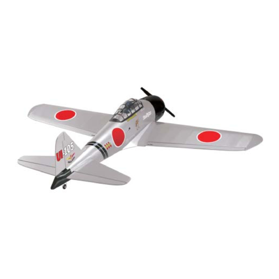
Hand-made Almost Ready to Fly R/C Model Aircraft
Specifications
Wingspan ----------------------- .148 cm--------------- 58.3 in.
Wing area ----------------------- 3474sq. cm ---- 538.4sq in.
Approximate flying weight ----- 2.8 - 3.0kg ----6.2 - 6.6 lb.
Recommended engine size ---------- 0.40 - .48 2 stroke.
Recommended R/C ------------- 4 channel with 5 servos.
Flying skill level ------------------- Advanced / Intermediate.
Kit features
•
Ready-made—minimal assembly & finishing required
•
Ready-covered covering
•
Factory-installed pushrods
•
Factory-installed engine mount
•
Factory-pinned & glued control surface hinges for ultimate safety
•
Comprehensive hardware pack including wheels, tank, spats,undercarriage& spinner
•
Photo-illustrated step-by-step Assembly Manual
Made in Vietnam
ASSEMBLY MANUAL
0.50 - .72 4 stroke.
Additional items required
Engine
4 Channel or greater Radio Control system
Glues
Tools
Starting Equipment
Advertisement
Table of Contents

Related Manuals for Seagull Models ZERO FIGHTER


Summary of Contents for Seagull Models ZERO FIGHTER
- Page 1 Hand-made Almost Ready to Fly R/C Model Aircraft ASSEMBLY MANUAL Specifications Additional items required Wingspan ----------------------- .148 cm--------------- 58.3 in. Engine Wing area ----------------------- 3474sq. cm ---- 538.4sq in. 4 Channel or greater Radio Control system Approximate flying weight ----- 2.8 - 3.0kg ----6.2 - 6.6 lb. Glues Recommended engine size ---------- 0.40 - .48 2 stroke.
-
Page 2: Instruction Manual
Flying the Zero fighter is simply a joy. This instruction manual is designed to help you build a great flying aeroplane. Please read this manual thoroughly before starting assembly of your Zero fighter . Use the parts listing below to identify all parts. - Page 3 This will ensure proper assembly as the Zero fighter is made from natu- ral materials and minor adjustments may have to be made. The paint and plastic parts used in this kit are fuel proof.
-
Page 4: Landing Gear Installation
ZERO FIGHTER. Instruction Manual ! 5) Remove the two straps and the gear LANDING GEAR INSTALLATION wire. Drill four 1.5mm pilot holes into the wing PARTS REQUIRED for the wood screws. Be careful not to drill through the top of the wing! -
Page 5: Installing The Aileron Servos
ZERO FIGHTER. INSTRUCTION MANUAL INSTALLING THE AILERON SERVOS. 2) Attach the string to one end of servo lead and carefully thread it though the wing. Once you have thread the lead throught the wing, remove the string so it can use for the ! 1) Use a small weight(Weighted fuel pick- other servo lead. -
Page 6: Installing The Aileron Linkage
ZERO FIGHTER. Instruction Manual INSTALLING THE AILERON LINKAGE PARTS REQUIRED ! {2} 2mm x 180mm Threaded Wires ! {2} Nylon Adjustable Control Horns ! {2} Nylon Clevises ! {4} Machine screws 2MM x 20MM ! {2} Set control horns. ! 1) Using a ruler & pen to draw a straight line as below picture. - Page 7 ZERO FIGHTER. INSTRUCTION MANUAL ! ! ! ! ! 4) Using a 1mm drill bit and the control horns Cut the wire 1/2” past the mark and as a guide, drill the mounting holes through make an “ L ” bend .
-
Page 8: Wing Assembly
ZERO FIGHTER. Instruction Manual WING ASSEMBLY Epoxy NOTE: We highly recommend using 30 minute epoxy as it is stronger and provides more working time, allowing the builder to properly align the parts. Using fast cure epoxy when joining the wing halves could result in the... -
Page 9: Installing The Canopy
ZERO FIGHTER. INSTRUCTION MANUAL INSTALLING THE PILOT. ! 1.If you plan on using a pilot in your Zero fighter .46, now is the time to mount it to the cockpit floor area of the hatch. ! 2. After cutting out the canopy, trial fit it to fuselage. -
Page 10: Adding Decals
ZERO FIGHTER. Instruction Manual ADDING DECALS. ! 1.Locate the decal sheet include in the kit. Use the box art photos and some pictures below as an approximate position reference for the application of the inclued decals. FUEL TANK PARTS REQUIRED... -
Page 11: Installing The Fuel Tank
ZERO FIGHTER. INSTRUCTION MANUAL ! 4) Test fit the stopper assembly into the tank. It may be necessary to remove some of the flashing around the tank opening using a modeling knife. If flashing is present, make sure none falls into the tank. -
Page 12: Mounting The Engine
ZERO FIGHTER. Instruction Manual Pushrod Wire Wood block 4pcs ! 2) Feed both lines through the fuel tank compartment and through the predrilled hole in the firewall. Pull the lines out from behind the engine, while guiding the fuel tank into place. -
Page 13: Propeller & Spinner
ZERO FIGHTER. INSTRUCTION MANUAL ! ! ! ! ! 3) Attach the Z-Bend in the pushrod wire Muffler exhaust to the throttle arm on the carburetor. You will need to remove the throttle arm from the car- buretor to be able to attach the Z-bend. When complete, reattach the throttle arm to the car- buretor. -
Page 14: Installing The Fuselage Servos
ZERO FIGHTER. Instruction Manual INSTALLING THE SERVOS ! 1. Install the rubber grommets and brass collets onto the elevator, rudder and throttle servos. Test fit the servos into the preinstalled servo tray.Because the size of servos differ, you may need to adjust the size of the precut openings in the tray. - Page 15 ZERO FIGHTER. INSTRUCTION MANUAL Make mark and cut 3 slots for pushrod exit follow picture below. Ruller paper A4 size Draw 2columns with 2mm width Elevator pushrod slot exit 5.5 cm 5 cm...
-
Page 16: Tail Wheel Installation
ZERO FIGHTER. Instruction Manual TAIL WHEEL INSTALLATION. Connector (3 pcs) Connector (3 pcs) Connector (3 pcs) Stearing arm Elevator pushrod slot exit Fuselage Connector Connector Tail wheel pushrod exit slot Draw a straight line - continue with rudder slot INSTALLATION THE HORIZONTAL STABILIZER... -
Page 17: Vertical Stabilizer Installation
ZERO FIGHTER. INSTRUCTION MANUAL The top of the stabilizer does not have the hinge pins exposed. Remove covering ! 2) Using a modeling knife, carefully re- move the covering from over the vertical sta- bilizer mounting slot in the top of the fuselage. -
Page 18: Aligning The Vertical Stabilizer
ZERO FIGHTER. Instruction Manual Remove covering ALIGNING THE VERTICAL STABILIZER When cutting through the covering to remove it, cut with only enough pres- sure to only cut through the covering it- self. Cutting into the balsa structure may ! 1) Using a modeling knife, remove the weaken it. - Page 19 ZERO FIGHTER. INSTRUCTION MANUAL ! ! ! ! ! 5) Rudder pushrod installation as same as picture below Pushrod wire Control Horn TAIL WHEEL PUSHROD INSTALLATION Mounting Screws Mounting Plate Stearing arm ! ! ! ! ! 3) Using a 1mm drill bit and the control horn as a guide, drill the mounting holes through the rudder .
- Page 20 ZERO FIGHTER. Instruction Manual WING ATTACHMENT TO FUSELAGE Control Horn Mounting Screws Mounting Plate ! ! ! ! ! 3) Using a 1mm drill bit and the control horn as a guide, drill the mounting holes through the elevator .
-
Page 21: Flight Preparation
ZERO FIGHTER. INSTRUCTION MANUAL ! E)From behind the airplane, look at the BALANCING aileron on the right wing half. Move the aileron ! 1) It is critical that your airplane be bal- stick to the right. The right aileron should move anced correctly. -
Page 22: Preflight Check
Rate (initial test flying/sport flying) and High Rate (aerobatic flying). ! 2) Check every bolt and every glue joint in the ZERO FIGHTER to ensure that every- ! 2) Turn on the radio system, and with the thing is tight and well bonded.
Need help?
Do you have a question about the ZERO FIGHTER and is the answer not in the manual?
Questions and answers