Table of Contents
Advertisement
Quick Links
Code : SEA 334
ASSEMBLY MANUAL
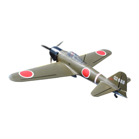
Speciications:
Wingspan--------------- 86.0 in (218.4 cm).
Wing area--------------- 1168.7sq.ins (75.4 sq.dm).
Weight------------------- 21.6 lbs (9.8 kg).
Length------------------- 65.0 in (165.0 cm).
Engine/Motor size----- 50-60cc gasoline.
Radio--------------------- 7 channels with 8 servos.
SEA 334 : Without electric retracts landing gear.
SEA334gear: including Electric retracts landing gear.
1
Advertisement
Table of Contents

Related Manuals for Seagull Models SEA 334


Summary of Contents for Seagull Models SEA 334
- Page 1 Wingspan--------------- 86.0 in (218.4 cm). Wing area--------------- 1168.7sq.ins (75.4 sq.dm). Weight------------------- 21.6 lbs (9.8 kg). Length------------------- 65.0 in (165.0 cm). Engine/Motor size----- 50-60cc gasoline. Radio--------------------- 7 channels with 8 servos. SEA 334 : Without electric retracts landing gear. SEA334gear: including Electric retracts landing gear.
-
Page 2: Kit Contents
Instruction Manual. Giant Zero A6M Gas ARF 50-60cc, 86” INTRODUCTION hank you for choosing the Giant Zero A6M Gas ARF 50-60cc, 86” ARTF by SG MOD- ELS . he Giant Zero A6M Gas ARF 50-60cc, 86” was designed with the intermediate/ advanced sport lyer in mind. -
Page 3: Additional Items Required
KIT CONTENTS HINGING THE FLAP SEA334 Giant Zero A6M Gas ARF 50-60cc, 86” 1. Fuselage 2. Wing set (2) 3. Tail set (2) 4. Canopy 5. Cowling 6. Wing tube 7. Pilot 8. landing gear 9. Fuel tank 10. Tail wheel 2x10mm ADDITIONAL ITEMS REQUIRED �... -
Page 4: Hinging The Aileron
Instruction Manual. Giant Zero A6M Gas ARF 50-60cc, 86” Remove each hinge from the wing panel and aileron and place a T-pin in the center of each hinge. Slide each hinge into the wing panel until the T-pin is snug against the wing panel. - Page 5 Hinge Note : Work the aileron up and down sev- eral times to “work in” the hinges Epoxy and check for proper movement. WING TIP BULBS Please see below pictures. Turn the wing panel over and delect the aileron in the opposite direction from the opposite side.
- Page 6 Instruction Manual. Giant Zero A6M Gas ARF 50-60cc, 86” INSTALL THE AILERONS CONTROL HORN Fiberglass control horn CA glue Epoxy Ailerons control horn CA glue...
-
Page 7: Installing The Aileron Servos
INSTALL FLAP CONTROL HORN INSTALLING THE AILERON SERVOS Install the lap control horn using the same method as same as the aileron con- trol horns. Fiberglass control horn Minimum servo spec. Torque : 194 oz-in (14 kg-cm) @ 6.0V; 236 oz-in ( 17kg-cm) @ 7.4V Because the size of servos difer, you Epoxy may need to adjust the size of the precut... - Page 8 Instruction Manual. Giant Zero A6M Gas ARF 50-60cc, 86” Use dental loss or heatshrink tube to secure the connection so they cannot be- come unplugged. Secure the servo to the aileron hatch using Phillips screwdriver and the screws Use drill bit in a pin vise to drill the provided with the servo.
- Page 9 Set the aileron hatch in place and use a Phillips screw driver to install it with four wood screws. 3x10mm INSTALLING THE FLAP SERVO Repeat the procedure for the lap servo.
-
Page 10: Aileron Pushrod Installation
Instruction Manual. Giant Zero A6M Gas ARF 50-60cc, 86” AILERON PUSHROD INSTALLATION INSTALLING THE FLAP PUSHROD Please see below pictures. 75mm 75mm INSTALLING LANDING GEAR Locate items necessary to install Sprin Landing Gear. - Page 11 Epoxy...
- Page 12 Instruction Manual. Giant Zero A6M Gas ARF 50-60cc, 86” Mark 3x15mm...
- Page 13 Collar M3x4mm Collar M3x4mm Secure the landing gear doors to the landing gear struts. 3x10mm head locker glue...
- Page 14 Instruction Manual. Giant Zero A6M Gas ARF 50-60cc, 86” 3x10mm...
-
Page 15: Wing Assembly
ASEMBLE BOMB INTO THE WING WING ASSEMBLY 3x15mm... -
Page 16: Installing The Fuselage Servos
Instruction Manual. Giant Zero A6M Gas ARF 50-60cc, 86” INSTALLING THE FUSELAGE SERVOS Rudder servo arm Elevator servo arm Because the size of servos difer, you may need to adjust the size of the precut opening in the mount. he notch in the sides of the mount allow the servo lead to pass through. -
Page 17: Installing The Stopper Assembly
INSTALLING THE ENGINE SWITCH Trim and cut Carefully bend the second nylon tube up at a 45º angle. his tube is the vent tube. Test it the stopper assembly into the tank. It may be necessary to remove some of the lashing around the tank opening using a modeling knife. -
Page 18: Mounting The Engine
Instruction Manual. Giant Zero A6M Gas ARF 50-60cc, 86” Connect the lines from the tank to the You should mark which tube is the vent engine and muler. he vent line will and which is the fuel pickup when you attach fuel tubing to the tubes in the stopper. - Page 19 Locate the engine mounting in position on the irewall. Use a 2.5mm drill bit to drill the holes necessary to mount your particular motor choice. 2.5mm Mark Mark Mark...
- Page 20 Instruction Manual. Giant Zero A6M Gas ARF 50-60cc, 86” 170mm Pushrod wire...
- Page 21 Ignition Modude...
- Page 22 Instruction Manual. Giant Zero A6M Gas ARF 50-60cc, 86” Reinstall the servo horn by sliding the connector over the pushrod wire. Center the throttle stick and trim and install the servo horn perpendicular to the servo center line.
- Page 23 COWLING Please see below pictures. Epoxy...
- Page 24 Instruction Manual. Giant Zero A6M Gas ARF 50-60cc, 86” Tape the cowl to the fuselage using low- tack tape. Mark Use a drill and drill bit to drill the holes for the cowl mounting screws. Make sure the cowl position is correct before drill- ing each hole.
- Page 25 Install the muler and muler exten- sion onto the engine and make the cutout in the cowl for muler clearance. Connect the fuel and pressure lines to the carbu- retor, muler and fuel iler valve. Secure the cowl to fuselage using the M3x10mm socket head screws.Putting a small length of silicon fuel tube under the head of the screw helps with vibration.
- Page 26 Instruction Manual. Giant Zero A6M Gas ARF 50-60cc, 86” ELECTRIC POWER CONVERSION Mark Locate the items neccessary to install the electric power conversion included with your model. Recommend the items necessary to in- stall the electric power conversion parts included with your model. - Motor: 360 - 6000 Watts - Propeller: 24x10 ~ 25x12 - ESC: 160A - 200A...
- Page 27 M5x30mm and washers. 5mm. hen, use 7mm drill bit to enlarge the Attach the motor mount to the front of the holes on the electric motor box. electric motor box using four 5mm blind nut, four M5x30mm hex head bolts to se- cure the motor.
- Page 28 Instruction Manual. Giant Zero A6M Gas ARF 50-60cc, 86” Blind nut M5x20mm 170mm...
-
Page 29: Installing The Spinner
INSTALLING THE SPINNER Install the spinner backplate, propeller and spinner cone. Attach the speed control to the side of the motor box using two-sided tape and tie wraps. Connect the appropriate leads from the speed control to the motor. Make sure the leads will not interfere with the he propeller should not touch any operation of the motor. - Page 30 Instruction Manual. Giant Zero A6M Gas ARF 50-60cc, 86” Epoxy...
- Page 31 Epoxy Epoxy INSTALL RUDDER CONTROL HORN Epoxy...
-
Page 32: Installing The Horizontal Stabilizer
Instruction Manual. Giant Zero A6M Gas ARF 50-60cc, 86” INSTALLING THE HORIZONTAL STABILIZER Please see below pictures. Epoxy... - Page 33 INSTALL ELEVATOR CONTROL HORN Epoxy Epoxy...
-
Page 34: Rudder Pushrod Installation
Instruction Manual. Giant Zero A6M Gas ARF 50-60cc, 86” RUDDER PUSHROD INSTALLATION Repeat steps as same as steps done for elevator. Epoxy M2 clevis M2 lock nut... -
Page 35: Installation
ELEVATOR PUSHROD HORN INSTALL ELEVATOR CONTROL HORN INSTALLATION... -
Page 36: Mounting The Tail Wheel
Instruction Manual. Giant Zero A6M Gas ARF 50-60cc, 86” MOUNTING THE TAIL WHEEL Locate items necessary to install tail wheel. - Page 37 Epoxy INSTALLATION COCKPIT, PILOT AND CANOPY Locate items necessary to install.
- Page 38 Instruction Manual. Giant Zero A6M Gas ARF 50-60cc, 86” A scale pilot is included with this ARF. he Pilot included itting well to the Epoxy cockpit. (or you can order others scale pilot igures made by SG Models. hey are available at SG Models distributors.) If you are going to install a pilot igure, please use a sanding bar to sand the base of the igure so that it is lat.
- Page 39 Epoxy INSTALLING NEEDED ANTEN Parts requirement.See pictures below. Epoxy Epoxy canopy onto the fuselage. Trace around the canopy and onto the fuselage using a epoxy.
- Page 40 Instruction Manual. Giant Zero A6M Gas ARF 50-60cc, 86” Route the antenna in the antenna tube inside the fuselage and secure it to the bottom of fuselage using a plastic tape. Battery Receiver ATTACKMENT WING-FUSELAGE INSTALLING THE BATTERY-RECEVER Plug the servos leads and the switch lead into the receiver.
- Page 41 hen, install wing guns on the wings. Wing bolt...
-
Page 42: Apply The Decals
Instruction Manual. Giant Zero A6M Gas ARF 50-60cc, 86” *If possible, irst attempt to balance the APPLY THE DECALS model by changing the position of the re- ceiver battery and receiver. If you are un- 1) If all the decals are precut and ready to able to obtain good balance by doing so, stick. -
Page 43: Control Throws
150mm CONTROL THROWS Ailerons: Rudder: High Rate : High Rate : Up : 25 mm Right : 30 mm Down : 25 mm Let : 30 mm Low Rate : Low Rate : Up : 20 mm Right : 20 mm Down : 20 mm Let : 20 mm Elevator:... - Page 44 Instruction Manual. Giant Zero A6M Gas ARF 50-60cc, 86” 15-20mm 15-20mm 20-30mm Fuselage 20-30mm 20-25mm Wing 20-25mm 30mm 70mm...
-
Page 45: Flight Preparation
FLIGHT PREPARATION. PREFLIGHT CHECK. Check the operation and direction of the 1) Completely charge your transmit- elevator, rudder, ailerons and throttle. ter and receiver batteries before your irst day of lying. A) Plug in your radio system per the 2) Check every bolt and every glue manufacturer’s instructions and turn eve- joint in the Giant Zero A6M Gas ARF rything on. - Page 46 Instruction Manual. Giant Zero A6M Gas ARF 50-60cc, 86” If you have any queries, or are interested in our products, please feel free to contact us Factory : 12/101A - Hamlet 4 - Le Van Khuong Street - Dong hanh Ward - Hoc Mon District - Ho Chi Minh City - Viet Nam.
Need help?
Do you have a question about the SEA 334 and is the answer not in the manual?
Questions and answers