Table of Contents
Advertisement
Quick Links
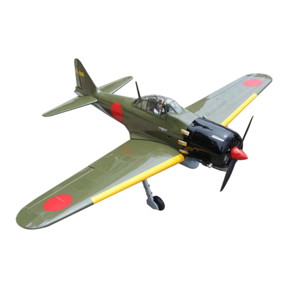
Upgraded A6M Zero
Fighter 67", 15-20cc
Code : SEA 123N
ASSEMBLY MANUAL
Speciications:
Wing span ---------------------- 67.0 in (170 cm).
Wing area ---------------------- 761.1 sq.in (49.1sq dm).
Weight -------------------------- 10.8 lbs (4.9 kg).
Length -------------------------- 51.1 in (129.8 cm).
Engine -------------------------- 15-20cc
Radio --------------------------- 5 channels with 7 servos.
Retracts landing gear (included).
Electric conversion: optional
1
Advertisement
Table of Contents

Subscribe to Our Youtube Channel
Related Manuals for Seagull Models A6M Zero Fighter 67


Summary of Contents for Seagull Models A6M Zero Fighter 67
- Page 1 Upgraded A6M Zero Fighter 67”, 15-20cc Code : SEA 123N ASSEMBLY MANUAL Speciications: Wing span ---------------------- 67.0 in (170 cm). Wing area ---------------------- 761.1 sq.in (49.1sq dm). Weight -------------------------- 10.8 lbs (4.9 kg). Length -------------------------- 51.1 in (129.8 cm). Engine -------------------------- 15-20cc Radio --------------------------- 5 channels with 7 servos.
-
Page 2: Kit Contents
Zero Fighter 67”, 15-20cc his instruction manual is designed to help you build a great lying aeroplane. Please read this manual throughly before starting assembly of your Up- graded A6M Zero Fighter 67”, 15-20cc Use the parts listing below to indentify all parts. WARNING Please be aware that this aeroplane is not a toy and if assembled or used incorrectly it is ca- pable of causing injury to people or property. -
Page 3: Additional Items Required
KIT CONTENTS HINGING THE FLAP SEA123N Upgraded A6M Zero Note : he control surfaces, including the ailer- Fighter 67”, 15-20cc ons, elevators, and rudder, are prehinged with 1. Fuselage hinges installed, but the hinges are not glued in 2. Wing set (2) place. -
Page 4: Hinging The Aileron
Instruction Manual. Upgraded A6M Zero Fighter 67”, 15-20cc Repeat this process with the other wing Delect the and completely satu- panel, securely hinging the aileron in rate each hinge with thin C/A glue. he place ailerons front surface should lightly con- tact the wing during this procedure. - Page 5 Remove each hinge from the wing panel NOTE : he hinge is constructed of a spe- and aileron and place a T-pin in the center cial material that allows the C/A to wick of each hinge. Slide each hinge into the wing or penetrate and distribute throughout panel until the T-pin is snug against the wing the hinge, securely bonding it to the wood...
- Page 6 Instruction Manual. Upgraded A6M Zero Fighter 67”, 15-20cc Repeat this process with the other wing panel, securely hinging the aileron in place Ater both ailerons are securely hinged, irmly grasp the wing panel and aileron to make sure the hinges are securely glued and cannot be pulled out.
- Page 7 Remove the control horns from the control surfaces. Apply epoxy to the slot in the aileron and lap. Make sure the epoxy gets into the slot for a good bond between the surfaces and control horn. Epoxy INSTALL FLAP CONTROL HORN Install the lap control horn using the same method as same as the aileron con- trol horns.
-
Page 8: Installing The Aileron Servos
Instruction Manual. Upgraded A6M Zero Fighter 67”, 15-20cc Minimum servo spec. Torque : 80 oz-in (5.8 kg-cm) @ 4.8V; 100 oz-in (7.2 kg-cm) @ 6.0V Epoxy Because the size of servos difer, you may need to adjust the size of the precut Flap control horn opening in the mount. - Page 9 Remove the string from the wing at the servo location and use the tape to attach it to the servo extension lead. Pull the lead through the wing and remove the string. C/A glue Use dental loss or heatshrunk tube to secure the connection so they cannot be- come unplugged.
-
Page 10: Aileron Pushrod Installation
Instruction Manual. Upgraded A6M Zero Fighter 67”, 15-20cc AILERON PUSHROD INSTALLATION Set the aileron hatch in place and use a Phillips screw driver to install it with four Mark the control wire where it crosses wood screws. the servo arm hole. - Page 11 Wing M2 lock nut Connect the linkage as shown and secure the control wire with a snap keeper. Flap INSTALLING RETRACTABLE LANDING GEAR Locate items necessary to install Sprin Landing Gear. You use this fork set JP ER-120-84degree. INSTALLING THE FLAP PUSHROD Repeat the procedure for the aileron pushrod.
- Page 12 Instruction Manual. Upgraded A6M Zero Fighter 67”, 15-20cc 3x20mm 3x10mm...
- Page 13 3x4mm 3x4mm 4x5mm...
-
Page 14: Installing The Fuselage Servos
Instruction Manual. Upgraded A6M Zero Fighter 67”, 15-20cc Collar 3x4mm INSTALLING THE FUSELAGE SERVOS Because the size of servos difer, you may need to adjust the size of the precut opening in the mount. he notch in the sides of the mount allow the servo lead to pass through. -
Page 15: Installation
Rudder servo arm hrottle servo arm Rudder servo Tail wheel Elevator servo arm hrottle servo Elevator servo INSTALLING THE RECEIVER SWITCH Secure the servos with the screws pro- vided with your radio system. Install the switch into the precut hole in the side, in the fuselage. - Page 16 Instruction Manual. Upgraded A6M Zero Fighter 67”, 15-20cc INSTALLING THE ENGINE SWITCH Trim and cut Switch Vent tube Fuel pick up tube INSTALLING THE STOPPER ASSEMBLY Fuel ill tube Using a modeling knife, carefully cut of the rear portion of one of the 3 nylon tubes leaving 1/2”...
-
Page 17: Fuel Tank Installation
When satisied with the alignment of the stopper assembly tighten the 3 x 20mm ma- chine screw until the rubber stopper expands and seals the tank opening. Do not over- tighten the assembly as this could cause the tank to split. FUEL TANK INSTALLATION You should mark which tube is the vent and which is the fuel pickup when you attach... -
Page 18: Mounting The Engine
Instruction Manual. Upgraded A6M Zero Fighter 67”, 15-20cc Connect the lines from the tank to the engine and muler. he vent line will connect to the muler and the line from the clunk tothe carburetor. Blow through one of the lines to ensure the fuel lines have not become kinked inside the fuel tank compartment. - Page 19 Pushrod wire 4x25mm On the ie wall has the location for the throttle pusshrod tube (pre-drill). Slide the pushrod tube in the iewall and guide it through the fuel tank mount. Use medium C/A to glue the tube to the ie- wall and the fuel tank mount.
- Page 20 Instruction Manual. Upgraded A6M Zero Fighter 67”, 15-20cc Ignition Modude...
- Page 21 COWLING Please see below pictures. Reinstall the servo horn by sliding the connector over the pushrod wire. Center the throttle stick and trim and install the servo horn perpendicular to the servo center line. Move the throttle stick to the closed po- sition and move the carburetor to closed.
- Page 22 Instruction Manual. Upgraded A6M Zero Fighter 67”, 15-20cc Use a drill and drill bit to drill the holes for the cowl mounting screws. Make sure the cowl position is correct before drill- ing each hole. Install the muler and muler exten- sion onto the engine and make the cutout in the cowl for muler clearance.
- Page 23 ELECTRIC POWER CONVERSION Locate the items neccessary to install the electric power conversion included with your model. Recommend the items necessary to in- stall the electric power conversion parts included with your model. - Motor: 110 - 2000 Watts - Propeller: 17x8 ~ 19x10 - ESC: 85A - 6S- 8S Lipo Attach the electric motor box to the ire-...
- Page 24 Instruction Manual. Upgraded A6M Zero Fighter 67”, 15-20cc hen, use 4mm drill bit to enlarge the holes on the electric motor box. M4x25mm and washers Attach the motor mount to the front of the electric motor box using four 4mm blind nut, four M4x25mm hex head bolts to se- cure the motor.
- Page 25 Attach the speed control to the side of the motor box using two-sided tape and tie wraps. Connect the appropriate leads from the speed control to the motor. Make sure the leads will not interfere with the operation of the motor. Speed control M4x20mm 150mm...
-
Page 26: Mounting The Tail Wheel
Instruction Manual. Upgraded A6M Zero Fighter 67”, 15-20cc MOUNTING THE TAIL WHEEL INSTALLING THE SPINNER Install the spinner backplate, propeller and spinner cone. he propeller should not touch any part of the spinner cone. If it does, use a sharp modeling knife and carefully trim away the spinner cone where the propel- ler comes in contact with it. -
Page 27: Installing The Horizontal Stabilizer
3x15mm Epoxy Epoxy INSTALLING THE HORIZONTAL INSTALL ELEVATOR CONTROL HORN STABILIZER Using a ruler and a pen, locate the cen- terline of the horizontal stabilizer, at the trailing edge, and place a mark. Use a tri- angle and extend this mark, from back to front, across the top of the stabilizer. - Page 28 Instruction Manual. Upgraded A6M Zero Fighter 67”, 15-20cc Using a modeling knife, carefully remove Remove the stabilizer. Using the lines you just drew as a guide, carefully remove the the covering at mounting slot of horizon- covering from between them using a mod- tal stabilizer ( both side of fuselage).
-
Page 29: Installing The Vertical Stabilizer
While holding the vertical stabilizer irmly Fill Epoxy in place, use a pen and draw a line on each side of the vertical stabilizer where it meets the top of the fuselage. Fill Epoxy INSTALLING THE VERTICAL Slide the vertical stabilizer back in place. STABILIZER Using a triangle, check to ensure that the ver- tical stabilizer is aligned 90º... -
Page 30: Hinging The Rudder
Instruction Manual. Upgraded A6M Zero Fighter 67”, 15-20cc HINGING THE RUDDER Glue the rudder hinges in place using the same techniques used to hinge the ailerons. -
Page 31: Elevator Pushrod Installation
- Install the elevator control horn using the same method as with the aileron con- trol horns. - Position the elevator control horn on the both side of elevator. Elevator control horn head one clevis and M2 lock nut on to each elevator control rod. -
Page 32: Rudder Pushrod Installation
Instruction Manual. Upgraded A6M Zero Fighter 67”, 15-20cc Screw RUDDER PUSHROD INSTALLATION Locate items necessaryto install rudder Screw pushrod. - Page 33 INSTALLATION COCKPIT, PILOT AND CANOPY Locate items necessary to install.
- Page 34 Instruction Manual. Upgraded A6M Zero Fighter 67”, 15-20cc Position the pilot igure on the canopy loor as show. Locate the oval shaped on the canopy loor and remove the cover- ing. Use epoxy to glue this into the base of the pilot igure and glue the cockpit panel in place with C/A glue, please see pictures as shown.
- Page 35 Epoxy canopy onto the fuselage. Trace around the canopy and onto the fuselage using a epoxy. Epoxy INSTALLING NEEDED ANTEN Parts requirement.See pictures below. Epoxy...
-
Page 36: Install The Plastic Parts
Instruction Manual. Upgraded A6M Zero Fighter 67”, 15-20cc Epoxy INSTALL THE PLASTIC PARTS Please see below pictures. - Page 37 Epoxy...
- Page 38 Instruction Manual. Upgraded A6M Zero Fighter 67”, 15-20cc ATTACKMENT WING-FUSELAGE Attach the aluminium tube into fuselage. Wing tube INSTALLING THE BATTERY-RECEVER Plug the servos leads and the switch lead into the receiver. Plug the battery pack lead into the switch also.
-
Page 39: Apply The Decals
APPLY THE DECALS 1) If all the decals are precut and ready to stick. Please be certain the model is clean and free from oily ingerprints and dust. Position decal on the model where de- sired, using the photos on the box and aid in their location. -
Page 40: Control Throws
Instruction Manual. Upgraded A6M Zero Fighter 67”, 15-20cc 3) With the model inverted, place your CONTROL THROWS ingers on the masking tape and carefully lit the plane. his is the point at which your model should balance for your irst... - Page 41 12-15mm 12-15mm 20-30mm Fuselage 20-30mm 12-15mm Wing 12-15mm 30mm...
-
Page 42: Flight Preparation
Instruction Manual. Upgraded A6M Zero Fighter 67”, 15-20cc FLIGHT PREPARATION. PREFLIGHT CHECK. Check the operation and direction of the 1) Completely charge your transmit- elevator, rudder, ailerons and throttle. ter and receiver batteries before your irst day of lying. A) Plug in your radio system per the 2) Check every bolt and every glue manufacturer’s instructions and turn eve-... - Page 43 If you have any queries, or are interested in our products, please feel free to contact us Factory : 12/101A - Hamlet 4 - Le Van Khuong Street - Dong hanh Ward - Hoc Mon District - Ho Chi Minh City - Viet Nam. Oice : 62/8 Ngo Tat To Street - Ward 19 - Binh hanh District - Ho Chi Minh City - Viet Nam Phone : 848 - 86622289 or 848- 36018777...
Need help?
Do you have a question about the A6M Zero Fighter 67 and is the answer not in the manual?
Questions and answers