Table of Contents
Advertisement
MS:148
ASSEMBLY MANUAL
"Graphics and specifications may change without notice".
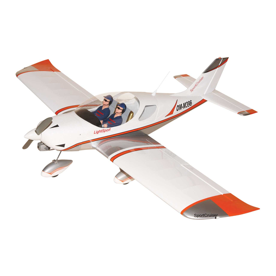
Specifications:
Wing span ------------------------------70.9in (180cm).
Wing area -----------------844.8sq.in (54.5sq dm).
Weight ------------------------9.7-10.6lbs (4.4-4.8kg).
Length ------------------------------49.7in (126.2cm).
Engine ------------------ 0.75-0.95cu.in -----2-stroke.
0.91-1.25cu.in -----4-stroke.
Radio ------------------- 6 channels with 7 servos.
Electric conversion: optional
Advertisement
Table of Contents

Related Manuals for Seagull Models SPORT CRUISER


Summary of Contents for Seagull Models SPORT CRUISER
- Page 1 MS:148 ASSEMBLY MANUAL “Graphics and specifications may change without notice”. Specifications: Wing span ------------------------------70.9in (180cm). Wing area -----------------844.8sq.in (54.5sq dm). Weight ------------------------9.7-10.6lbs (4.4-4.8kg). Length ------------------------------49.7in (126.2cm). Engine ------------------ 0.75-0.95cu.in -----2-stroke. 0.91-1.25cu.in -----4-stroke. Radio ------------------- 6 channels with 7 servos. Electric conversion: optional...
-
Page 2: Kit Contents
You will find that most of the work has been done for you already.The motor mount has been fitted and the hinges are pre-installed . Flying the SPORT CRUISER is simply a joy. This instruction manual is designed to help you build a great flying aeroplane. Please read this manual thoroughly before starting assembly of your SPORT CRUISER . - Page 3 www.seagullmodels.com HINGING THE FLAP . CONTENTS.S SEA14801 Fuselage Note: The control surfaces, including the SEA14802 Wing Set ailerons, elevators, and rudder, are SEA14803 Tail Set prehinged with hinges installed, but SEA14804 Cowling the hinges are not glued in place. It SEA14805 Wheel Pants is imperative that you properly...
-
Page 4: Hinging The Aileron
Instruction Manual. SPORT CRUISER 8) After both flap are securely hinged, firmly grasp the wing panel and flap to make sure the hinges are securely glued and cannot be pulled out. Do this by carefully applying medium pressure, trying to separate the flap from the wing panel. - Page 5 www.seagullmodels.com T-pin. Hinge. 3) Slide the aileron on the wing panel until there is only a slight gap. The hinge is now centered on the wing panel and aileron. Remove the T-pins and snug the aileron against the wing panel. A gap of 1/64” or less should be maintained between the wing panel and aileron.
-
Page 6: Hinging The Elevator
Instruction Manual. SPORT CRUISER HINGING THE ELEVATOR. Glue the rudder hinges in place using the same techniques used to hinge the ailerons. Aileron control horn. Epoxy HINGING THE RUDDER. Glue the rudder hinges in place using the same techniques used to hinge the ailerons. -
Page 7: Engine Mount Installation
www.seagullmodels.com INSTALL ELEVATOR CONTROL HORN. Rudder control horn. ENGINE MOUNT INSTALLATION. Fiberglass control horn. 1) Locate the items necessary to install the engine mount included with your model. . Epoxy 4x30mm. 2) Use four 4x30mm head bolts and four 4mm washers to attach the engine mount rails to the firewall. -
Page 8: Installing The Stopper Assembly
Instruction Manual. SPORT CRUISER INSTALLING THE STOPPER ASSEMBLY. 3) Carefully bend the second nylon tube up at a 45º angle. This tube is the vent tube. 1) Using a modeling knife, carefully cut 4) Test fit the stopper assembly into the off the rear portion of one of the 3 nylon tubes tank. -
Page 9: Installing The Fuselage Servos
www.seagullmodels.com 8) Use plywood template to hold in place INSTALLING THE FUSELAGE SERVOS. the fuel tank with C/A glue to secure the fuel tank inside the fuselage. Because the size of servos differ, you may need to adjust the size of the precut open- ing in the mount. -
Page 10: Installing The Switch
Instruction Manual. SPORT CRUISER 2) Follow diagram below for wheel pant INSTALLING THE SWITCH. installation: Install the switch into the precut hole in the Lite -Plywood side, in the fuselage. block. Wheel Collar. 3/ 32” Hole. Landing Gear. Axle. Nut. -
Page 11: Installing The Main Landing Gear
www.seagullmodels.com INSTALLING THE MAIN LANDING GEAR. Landing Gear. wheel Pant. 1) The blind nuts for securing the landing gear are already mounted inside the fuselage. C/A glue. 2) Using the hardware provided, mount the main landing gear to the fuselage. 4x20 mm. -
Page 12: Landing Gear Installation
Instruction Manual. SPORT CRUISER 3) Use a drill to drill the four holes in the engine mount rails. 4.5mm. 9) Move the throttle stick to the closed position and move the carburetor to closed. Use a 2.5mm 4) On the fire wall has the location for the hex wrench to tighten the screw that secures throttle pusshrod tube (pre-drill). - Page 13 www.seagullmodels.com 4mm. 2mm. M3x6mm.
- Page 14 Instruction Manual. SPORT CRUISER COWLING. 1)Slide the fiberglass cowl over the engine and line up the back edge of the cowl with the marks you made on the fuselage then trim and cut as shown. 2)Install landing gear at the top Fuselage.
- Page 15 www.seagullmodels.com 2) Attach the electric motor box to the firewall 2) While keeping the back edge of the suitable with the cross lines drawn on the electric cowl flush with the marks, align the front of motor box and firewall. Using epoxy and balsa the cowl with the crankshaft of the engine.
- Page 16 Instruction Manual. SPORT CRUISER Balsa stick. Electric motor. 5.2mm. Epoxy. 4) Locate the plywood battery tray to the fuselage. Tighten the screws using machine screws M3x15mm to secure the tray in position. Battery. Battery. M3 x 15mm. M4x15mm. 5) Attach the speed control to the side of the motor box using two-sided tape and tie wraps.
-
Page 17: Installing The Spinner
www.seagullmodels.com INSTALLING THE SPINNER. Install the spinner backplate, propeller and Small weight. String. spinner cone. 2) Place the servo between the mounting blocks and space it from the hatch. Use a pencil to mark the mounting hole locations on the blocks. - Page 18 Instruction Manual. SPORT CRUISER 6) Secure the servo to the aileron hatch using Phillips screwdriver and the screws provided with the servo. 7) Apply 1-2 drops of thin C/A to each of the mounting tabs. Allow the C/A to cure without using accelerator.
- Page 19 www.seagullmodels.com AILERON PUSHROD HORN INSTALLATION 80mm. M3 clevis. M3 lock nut. 100mm. Wing. M2 lock nut. Aileron. 9) Set the aileron hatch in place and use a Phillips screw driver to install it with four wood screws. INSTALLING THE FLAP SERVO Repeat the procedure for the aileron servo.
-
Page 20: Installing The Horizontal Stabilizer
Instruction Manual. SPORT CRUISER INSTALLING THE HORIZONTAL STABILIZER. 1) Using a ruler and a pen, locate the centerline of the horizontal stabilizer, at the trail- ing edge, and place a mark. Use a triangle and extend this mark, from back to front, across the top of the stabilizer. - Page 21 www.seagullmodels.com 3) Slide the vertical stabilizer back in place. Using a triangle, check to ensure that the vertical stabilizer is aligned 90º to the hori- zontal stabilizer. Vertical Stabilizer. Horizontal 90º Stabilizer. INSTALLING VERITICAL FIN. Epoxy. 1) Using a modeling knife, remove the covering from over the precut hinge slot cut into the lower rear portion of the fuselage.
-
Page 22: Installation
Instruction Manual. SPORT CRUISER RUDDER PUSHROD HORN ELEVATOR PUSHROD HORN INSTALLATION. INSTALLATION. 1) Install the elevator control horn using the same method as with the aileron control horns. 2) Position the elevator control horn on the both side of elevator. - Page 23 www.seagullmodels.com INSTALLATION PILOT AND CANOPY. M2x6mm. 1) Locate items necessary to install pilot, and canopy. C/A glue. INSTALL THE PLASTIC PARTS. 1) Locate the items neccessary to install the plastic parts included with your models: 2) A scale pilot is included with this ARF. The Seagull Pilot included fitting well to the cockpit.
-
Page 24: Apply The Decals
Instruction Manual. SPORT CRUISER APPLY THE DECALS. 1) If all the decals are precut and ready to Wing tube. stick. Please be certain the model is clean and free from oily fingerprints and dust. Position decal on the model where desired, using the photos on the box and aid in their location. -
Page 25: Control Throws
www.seagullmodels.com Lift the model. If the tail drops when you lift, BALANCING. the model is “tail heavy” and you must add 1) It is critical that your airplane be weight* to the nose. If the nose drops, it is balanced correctly. Improper balance will “nose heavy”... -
Page 26: Flight Preparation
8) Properly balance the propeller. An out versing switch on your transmitter to change of balance propeller will cause excessive vi- the direction. bration which could lead to engine and/or air- frame failure. We wish you many safe and enjoyable flights with your SPORT CRUISER.
Need help?
Do you have a question about the SPORT CRUISER and is the answer not in the manual?
Questions and answers