Table of Contents
Advertisement
Quick Links
www.seagullmodels.com
MS: SEA 118
ASSEMBLY MANUAL
"Graphics and specifications may change without notice".
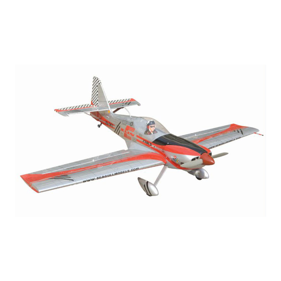
Specifications:
Wing span ----------------------------- 67.7in (172cm).
Wing area ------------------ 779.7sq.in (50.3sq dm).
Weight ------------------------- 8.6-9.7lbs (3.9-4.4kg).
Length -------------------------------- 49.1in (124.6cm).
Engine ----------------.75 - .91cu.in ---------2-stroke.
.91 - 1.00cu.in ------4-stroke.
Radio -------------- 6 channels with 5 digital servos.
Advertisement
Table of Contents

Related Manuals for Seagull Models ZLIN 50


Summary of Contents for Seagull Models ZLIN 50
- Page 1 www.seagullmodels.com MS: SEA 118 ASSEMBLY MANUAL “Graphics and specifications may change without notice”. Specifications: Wing span ----------------------------- 67.7in (172cm). Wing area ------------------ 779.7sq.in (50.3sq dm). Weight ------------------------- 8.6-9.7lbs (3.9-4.4kg). Length -------------------------------- 49.1in (124.6cm). Engine ----------------.75 - .91cu.in ---------2-stroke. .91 - 1.00cu.in ------4-stroke. Radio -------------- 6 channels with 5 digital servos.
-
Page 2: Kit Contents
ZLIN 50. INTRODUCTION. Thank you for choosing the ZLIN 50 ARTF by SEAGULL MODELS. The ZLIN 50 was designed with the intermediate/advanced sport scale in mind. It is a semi scale airplane which is easy to fly and quick to assemble. The airframe is conventionally built using balsa, plywood to make it stronger than the average ARTF , yet the design allows the aeroplane to be kept light. -
Page 3: Hinging The Ailerons
www.seagullmodels.com HINGING THE AILERONS. CONTEN.TS Note: The control surfaces, including the Fuselage ailerons, elevators, and rudder, are Canopy Left wing panel prehinged with hinges installed, but the Right wing panel hinges are not glued in place. It is Tail set imperative that you properly adhere the Aluminum wing tube hinges in place per the steps that follow... -
Page 4: Hinging The Elevator
Instruction Manual ZLIN 50. T- pin. Hinge. 5) Turn the wing panel over and deflect the aileron in the opposite direction from the 4)Deflect the aileron and completely opposite side. Apply thin C/A glue to each saturate each hinge with thin C/A glue. The... -
Page 5: Hinging The Rudder
www.seagullmodels.com Thread a control horn end with aluminum HINGING THE RUDDER. washer, lock nut until the top edge of the end is 18mm from the vase of the horn as shown. Glue the rudder hinges in place using the same techniques used to hinge the ailerons. CONTROL HORN M3 SCREW Epoxy. - Page 6 Instruction Manual ZLIN 50. INSTALL RUDDER CONTROL HORN. Repeat steps to install the rudder control horn as same as steps done for ailerons. 2 sets. 3x50mm. CONTROL HORN M3 Aluminum Washer Epoxy Horizontal Elevator. Stabilizer. Aluminum Washer M3 LOCK NUT Epoxy.
-
Page 7: Engine Mount Installation
www.seagullmodels.com Rudder control horn. INSTALLING THE BATTERY. ENGINE MOUNT INSTALLATION. 1) Locate the items necessary to install the engine mount included with your model. . Battery. Tie Wrap. M4 x 30mm. 2) Use four 4x30mm head bolts and four 4mm INSTALLING THE STOPPER ASSEMBLY. -
Page 8: Fuel Tank Installation
Instruction Manual ZLIN 50. FUEL TANK INSTALLATION. You should mark which tube is the vent and which is the fuel pickup when you attach fuel tubing to the tubes in the stopper. Once the tank is installed inside the fuselage, it may be difficult to determine which is which. - Page 9 www.seagullmodels.com 2) Follow diagram below for wheel pant installation: Vent tube. Use a drill and 4.2mm drill bit to drill a hole in the wheel pants. Drill a hole. 4.2mm. Fuel fill tube. 10mm. Fuel pick-up tube. 9) Connect the lines from the tank to the engine and muffler.
- Page 10 Instruction Manual ZLIN 50. 4) Slide the collar to the axle and setscrew Landing Gear. the collars to secure the collar to the axle and wheel Pant. then slider the wheel on the axle with a drop of oil on the axle so the wheel will spin freely when C/A glue.
-
Page 11: Installing The Switch
www.seagullmodels.com Repeat steps as above to attach remain- THROTTLE SERVO ARM INSTALLATION. ing wheel pants to the landing gear. Install adjustable servo connector in the servo INSTALLING THE MAIN LANDING GEAR arm as same as picture below: TO FUSELAGE. Loctite secure. 8) The blind nuts for securing the landing Adjustable Servo gear are already mounted inside the fuselage. -
Page 12: Mounting The Engine
Instruction Manual ZLIN 50. 4) On the fire wall has the location for the throttle pusshrod tube (pre-drill). Switch. MOUNTING THE ENGINE. 1) Position the engine with the drive washer (140mm) forward of the firewall as shown. 5) Slide the pushrod tube in the firewall and guide it through the fuel tank mount. -
Page 13: Cowling Installation
www.seagullmodels.com 8) Reinstall the servo horn by sliding the connector over the pushrod wire. Center the throttle stick and trim and install the servo horn Trim and cut. perpendicular to the servo center line. Because of the size of the cowl, it may be nec- essary to use a needle valve extension for the high speed needle valve. - Page 14 Instruction Manual ZLIN 50. 2) Attach the electric motor box to the firewall Needle valve. suitable with the cross lines drawn on the electric motor box and firewall. Using epoxy and balsa stick to secure the motor box to the firewall.
- Page 15 www.seagullmodels.com 3) Attach the motor to the front of the electric Blind nut. motor box using four 4mm blind nut, four M4x15mm hex head bolts to secure the motor. Please see picture shown. Balsa block. M4x15mm. 5.2mm. 4) Locate the plywood battery tray to the Epoxy.
-
Page 16: Spinner Installation
Instruction Manual ZLIN 50. 5) Attach the speed control to the side of the INSTALLING THE AILERON. motor box using two-sided tape and tie wraps. Connect the appropriate leads from the speed Servos. control to the motor. Make sure the leads will Small weight. - Page 17 www.seagullmodels.com 4) Apply 2-3 drops of thin C/A to each of the mounting holes. Allow the C/A to cure without using accelerator. 5) Use dental floss to secure the connection so they cannot become unplugged. 6) Secure the servo to the aileron hatch using Phillips screwdriver and the screws provided with the servo.
- Page 18 Instruction Manual ZLIN 50. 1) Mark the control wire where it crosses the servo arm hole. Bend at the mark. 2) Make a 90-degree bend at the mark and cut off the excess wire leaving 8mm past the bend. 9) Set the aileron hatch in place and use a Metal clevis.
-
Page 19: Wing Assembly
www.seagullmodels.com Repeat the procedure for the other aileron servo. WING ASSEMBLY. 1) Locate the items necessary to attach the wing. 2) Slide the aluminum wing tube into one of the wing panels. Only slide the tube in as far as it will easily slide. Forcing the tube could possibly damage the wing. -
Page 20: Installing The Horizontal Stabilizer
Instruction Manual ZLIN 50. Screw. M3x2.5mm. C/A glue. M3x2.5mm. INSTALLING THE HORIZONTAL STABILIZER. 1) Using a ruler and a pen, locate the centerline of the horizontal stabilizer, at the trail- ing edge, and place a mark. Use a triangle and extend this mark, from back to front, across the top of the stabilizer. - Page 21 www.seagullmodels.com 3) Put the stabilizer into place in the po- sition of the fuselage. 4) Install the stabilizer onto the fuselage. Align the centerline drawn on the top and the rear of the stabilizer with the centre of the fu- Remove covering.
-
Page 22: Installing The Vertical Stabilizer
Instruction Manual ZLIN 50. Fill epoxy. 10) After the epoxy has fully cured, re- move the masking tape or T-pins used to hold the stabilizer in place. Carefully inspect the glue joints. Use more epoxy to fill in any gaps... - Page 23 www.seagullmodels.com ELEVATOR - RUDDER PUSHROD HORN INSTALLATION. 1) Install tail struts included with your ARF. Cut small slot from the two indentations on the bottom of the horizontal tail. Epoxy. 4) When you are sure that everything is aligned correctly, mix up a generous amount of Flash 30 Minute Epoxy.
- Page 24 Instruction Manual ZLIN 50. 3) Attach the tail struts to the both 4) Install the elevator control horn using horizontal tail and fuselage with C/A glue. the same method as with the aileron control horns. Please see below pictures for easy installation the tail struts.
- Page 25 www.seagullmodels.com Control horn. Elevator pushrod. Rudder control horn. M2 lock nut. Metal clevis. Elevator control horn. Control horn. Rudder pushrod. 8) With both the rudder servo and rudder centered, mark the rudder pushrod at the hole it crosses in the rudder servo arm using a felt- tipped pen.
-
Page 26: Mounting The Tail Wheel
Instruction Manual ZLIN 50. M2 lock nut . M2 clevis. 8mm. 10) Elevator and rudder pushrods assembly follow pictures below. MOUNTING THE TAIL WHEEL. 11) Install servos arm to servos. Notice the position of the servo arms on the servos. - Page 27 www.seagullmodels.com Rudder pushrod. Cut. Elevator pushrod. INSTALLTION PILOT AND CANOPY. 1) Set the tail wheel assembly in place on the plywood plate. The pivot point of the tail 1) Locate items necessary to install pilot, wheel wire should be even with the rudder cockpit panel, and canopy.
-
Page 28: Apply The Decals
Instruction Manual ZLIN 50. 4) Position the canopy onto the fuselage. Trace INSTALLING THE BATTERY-RECEIVER. around the canopy and onto the fuselage using a felt-tipped pen. 1) Plug the five servo leads and the switch lead into the receiver. Plug the battery pack - Apply a bead of canopy glue around the inside edge of the canopy. - Page 29 www.seagullmodels.com BALANCING. 1) It is critical that your airplane be Tighten the antenna. balanced correctly. Improper balance will cause your plane to lose control and crash. THE CENTER OF GRAVITY IS LOCATED 95 MM BACK FROM THE LEADING EDGE OF THE WING AT THE WING ROOT. 2) Mount the wing to the fuselage.
-
Page 30: Control Throws
Instruction Manual ZLIN 50. CONTROL THROWS. Ailerons: 12mm - 15mm up. 95 mm. 12mm - 15mm down. Elevator: 10mm - 12mm up. 10mm - 12mm down. Rudder: 20mm - 30mm left. 20mm - 30mm right. FLIGHT PREPARATION. E) Check the throttle. Moving the throttle... -
Page 31: Preflight Check
6) Check to ensure the control surfaces 2) Check every bolt and every glue joint are moving the proper amount for both low in the ZLIN 50 to ensure that everything is and high rate settings. tight and well bonded.
Need help?
Do you have a question about the ZLIN 50 and is the answer not in the manual?
Questions and answers