Extreme Networks ExtremeWireless AP3935i Installation Manual
Hide thumbs
Also See for ExtremeWireless AP3935i:
- Installation manual (44 pages) ,
- Installation manual (46 pages)
Table of Contents
Advertisement
Advertisement
Table of Contents

Subscribe to Our Youtube Channel
Related Manuals for Extreme Networks ExtremeWireless AP3935i


Summary of Contents for Extreme Networks ExtremeWireless AP3935i
- Page 1 ExtremeWireless™ AP3935i & AP3935e Installation Guide P/N 9034915-01 January 2016...
-
Page 2: Legal Notices
Copyright © 2015 Extreme Networks, Inc. All Rights Reserved. Legal Notices Extreme Networks, Inc. reserves the right to make changes in specifications and other information contained in this document and its website without prior notice. The reader should in all cases consult representatives of Extreme Networks to determine whether any such changes have been made. -
Page 3: Table Of Contents
Vertical Radiation Pattern 5 GHz (XY Plane) .................... 23 Vertical Radiation Pattern 5 GHz (YZ Plane) .................... 23 External Antennas ............................24 Appendix B: Regulatory Information ExtremeWireless AP3935i and AP3935e ......................25 United States ............................. 25 FCC Declaration of Conformity Statement ..................25 USA Conformance Standards ......................26 FCC RF Radiation Exposure Statement.................... - Page 4 AP3935i Internal Antennas........................20 Certified External Antennas for AP3935e .................... 24 European Spectrum Usage Rules ....................... 32 Figures ExtremeWireless AP3935i top view....................... 2 ExtremeWireless AP3935e top view ..................... 3 AP3935 bottom view..........................3 AP3935 LEDs ............................4 Kensington Lock slot ..........................6 Attaching Mount Bracket to the Access Point..................
-
Page 5: About This Guide
About This Guide The guide describes how to mount and connect cables to the ExtremeWireless AP3935 access point. In addition, this guide provides information on the product certifications and national approvals for the AP3935 access point. NOTE This guide does not provide information on configuration of the access points. For information on how to configure the access points, see the ExtremeWireless User Guide. Who Should Use This Guide WARNING Electrical Hazard: Only qualified personnel should install or service this unit. Riesgo Electrico: Nada mas personal capacitado debe de instalar o darle servicio a esta unida. -
Page 6: Related Documents
Related Documents The following document can be obtained from the World Wide Web in Adobe Acrobat Portable Document Format (PDF) at the following location: https://extranet.extremenetworks.com/downloads/ • ExtremeWireless User Guide Typographical Conventions The following typographical conventions and icons are used in this document. Table 3-1 Typographical Conventions blue type Indicates a hypertext link. When reading this document online, click the text in blue to go to the referenced figure, table, or section. Lowercase x Indicates the general use of an alphanumeric character (for example, AP39xx, the x’s indicate a combination of numbers or letters). -
Page 7: Getting Help
Getting Help For additional support related to the AP3935 or this document, contact Extreme Networks using one of the following methods: www.Extreme Networks.com/support/ Phone 1-800-872-8440 (toll-free in U.S. and Canada) or 1-603-952-5000 For the Extreme Networks Support toll-free number in your country: www.Extreme Networks.com/support/ Before contacting Extreme Networks for technical support, have the following data ready: • Your Extreme Networks service contract number • A description of the failure • A description of any action(s) already taken to resolve the problem (for example, changing mode switches or rebooting the unit) • The serial and revision numbers of all involved Extreme Networks products in the network • A description of your network environment (such as layout, cable type, other relevant environmental information) •... - Page 8 viii...
-
Page 9: Chapter 1: Introduction
Introduction This installation guide provides an overview and installation instructions for the ExtremeWireless Access Points AP3935i and AP3935e. For information about... Refer to page... About the AP3935i and AP3935e AP3935 Overview Architectural Features About the AP3935i and AP3935e The AP3935 is designed to extend your Wireless LAN around indoor locations. The AP3935 supports the 802.11ac and 802.11n wireless standards, with full backward compatibility with legacy 802.11a, and 802.11b/g devices. The AP3935 interoperates fully with Wireless LANs, including support for VoWLAN, branch office mode, guest services, RTLS, availability, and mobility features. The operating Temperature: 0 ‐ 50C. The AP3935i and AP3935e have the following features in common: • Both support two MIMO 4x4 (up to four 802.11ac spatial streams). • They provide two single band radios for dual‐band, concurrent operation, optimized for indoor antenna coverage: – 5 GHz (Radio 1) in any of the following modes: IEEE802.11ac, a/b/g and/or n – 2.4 GHz (Radio 2) in any of the following modes: IEEE802.11ac, a/b/g and/or n • They are enclosed in a rectangular, compact case. -
Page 10: Ap3935 Overview
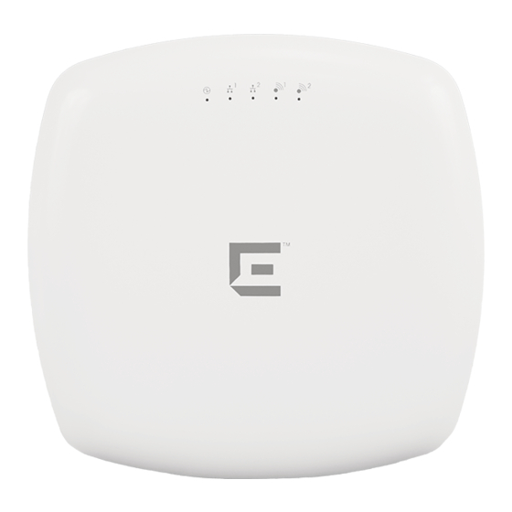
Within this document, any reference to AP3935 applies to both models. AP3935 Overview The AP3935 access point is available in two models: • AP3935i contains eight internal single‐band antennas • AP3935e contains eight external RSMA connectors for optional external antennas, for greater range and coverage versatility Figure 1‐1 on page 2 shows the top view of the AP3935i and Figure 1‐2 on page 3 shows the top view of the AP3935e. Figure 1‐3 on page 3 shows the bottom view of the AP3935e. The bottom view shows the location of the LAN ports, console port, external power supply connector, and reset switch.The bottom panel is the same for both models, but there are no external antenna RSMA connectors on the AP3935i. Figure 1‐4 on page 4 illustrates the AP3935 LEDs. Figure 1-1 ExtremeWireless AP3935i top view 2 AP3935 Overview... -
Page 11: Extremewireless Ap3935E Top View
Figure 1-2 ExtremeWireless AP3935e top view Figure 1-3 AP3935 bottom view 1 Reset Button 3 LAN Ethernet Ports 1 and 2 2 Console Port 4 External Power DC 12V ExtremeWireless™ AP3935 Installation Guide 3... -
Page 12: Ap3935 Led Indicators
AP3935 LED Indicators Both models of the AP3935 have the LED indicators, shown in Figure 1‐4 below. The LEDs provide status information, described in Table 1‐1, on the current state of the AP3935. For more information, see the ExtremeWireless User Guide. Figure 1-4 AP3935 LEDs 1 Status 4 Radio 1 (5 GHz) 2 LAN 1 (Ethernet 1) 5 Radio 2 (2.4 GHz) 3 LAN 2 (Ethernet 2) Table 1-1 AP3935 LED Indications Status Description 1 (AP status) On Green... -
Page 13: Architectural Features
Table 1-1 AP3935 LED Indications Status Description 2 (Ethernet link state) LAN 1 On Green Indicates a valid 10Mbps or 100Mbps Ethernet link. On Amber Indicates a valid 1Gbps Ethernet link. Indicates the link is down. 3 (Ethernet link state) LAN 2 On Green Indicates a valid 10Mbps or 100Mbps Ethernet link. -
Page 14: Kensington Lock Slot
Kensington Lock Slot There is a slot for a Kensington lock on the side of the AP (Figure 1‐5). See the Kensington lock documentation for instructions on use of the lock. Figure 1-5 Kensington Lock slot 6 Architectural Features... -
Page 15: Chapter 2: Installation
Installation This chapter provides installation instructions for the ExtremeWireless AP3935 access points and an optional AP power supply. For information about... Refer to page... Unpacking the AP3935 Accessories Access Point Installation Procedures Configuring AP3935e Channel Settings Unpacking the AP3935 To unpack the access point: Open the box and remove the packing material protecting the AP. Verify that the carton contains the items listed in Table 2‐1. Table 2-1 AP3935 Package Contents Quantity Item AP3935 Ceiling Mounting bracket Wall mounting screws and plastic anchors AP3935 Quick Reference Guide Hardware bag Perform a visual inspection of the AP for any signs of physical damage. Contact Extreme ... -
Page 16: Access Point Installation Procedures
Access Point Installation Procedures WARNING Electrical Hazard: Only qualified personnel should install or service this unit. Riesgo Electrico: Nada mas personal capacitado debe de instalar o darle servicio a esta unida. Elektrischer Gefahrenhinweis: Installationen oder Servicearbeiten sollten nur durch ausgebildetes und qualifiziertes Personal vorgenommen werden These procedures describe how to attach the AP3935 to a drop ceiling (flat or protruded), and how ... -
Page 17: Mounting The Ap3935 To A Wall
Remove the ceiling panels around the drop ceiling T‐bar rail and verify that the Ethernet cable can reach the AP at the mounting point. Slightly lift the movable T‐bar locking tab to increase the space between the stationary and the movable T‐bar sides of the bracket. Then hook the stationary end of the T‐bar bracket onto the T‐bar, as shown in Figure 2‐2. While holding the AP with one hand, reach the other hand over the T‐bar and grasp both the stationary and movable sides of the bracket. Push the bracket parts together so they both grasp the T‐bar and the locking tab clicks into place. While still holding the AP, rock it back and forth to ensure that it is securely mounted. Figure 2-2 Attaching the AP3935i on a drop ceiling T-bar rail Make a hole through the ceiling panel closest to the power slot on the AP. Run the Ethernet cable through the hole and into an RJ45 LAN port in the recessed connector bay. If necessary, cut the tiles for the cables, attach the cables to the AP, and replace the tiles. Replace the displaced ceiling panels. Mounting the AP3935 to a Wall Screws for attaching the AP to a wall are supplied with the product. Use the following procedure to mount the AP3935 to a flat wall: Determine the spot on the wall to mount the AP. Pick a spot near the ceiling, but in reach of the Ethernet cable and if you are using external power, near a wall power outlet. To mount the AP directly on the wall with two screws, use the provided template and mark the two drill holes on the wall. In drywall, the drill holes should be 6MM to 0.250ʺ in diameter. Drill two holes in the wall to match the center of the two keyhole slots in the back of the AP bracket. Screw the anchors into the holes until they are flush with the wall. Screw the provided mounting screws into the anchors with the head protruding about 5/32” ... -
Page 18: Mounting The Ap Using The Optional Mounting Bracket
Figure 2-3 Mounting the AP3935 to a Flat Wall. Place the back of the AP against the wall with the protruding mounting screw heads fitting through the keyhole slots on the back of the AP. Slide the AP down until the AP rests on the mounting screw heads. When mounting the AP on a wall or flat ceiling, a Kensington lock provides extra stability. NOTE The mounting bracket (30513, WS-MBI-WALL03) is optional when mounting the AP on a wall. If mounting the AP on a flat ceiling, we recommend using the mounting bracket (30513, WS-MBI-WALL03) for added security. -
Page 19: Lan/Console Connections
Use a magnetic screw driver to attach the small screw. Do NOT exceed 12 in‐lbs of torque. Use a Kensington lock for added security (see Figure 1‐5 on page 6). LAN/Console Connections NOTE LAN/Console connectors with shrouds will not fit into the ports. An optional jumper cable may be used or the shroud removed. The AP3935 has 2 LAN ports and a Console port. Power is provided through two Ethernet ports (LAN ports). This is the preferred method of powering the AP on ceiling and wall installations. The AP can be powered in one of the following ways: • Power over Ethernet (PoE) Power is provided through the RJ45 Ethernet port (LAN port) on the top of the AP. This is the preferred method of powering the AP on ceiling and high wall installations. • Power by external power supply Where a PoE‐capable Ethernet connection is unavailable or impractical, an external 12V DC power supply may be ordered separately to power the AP from a standard AC wall outlet. Figure 2-5 3935e Access Point bottom view 1 Reset Button 3 LAN Ethernet Ports 1 and 2... -
Page 20: Configuring Ap3935E Channel Settings
Configuring AP3935e Channel Settings The AP3935e must be installed by a professional installer. Before starting the installation, the installer needs to determine and configure the following: • Determine the Antenna Model • Configure Radio RF Port • Configure Radio Channel • Configure Radio Transmit (Tx) Power Determine the Antenna Model The professional installer needs to determine antenna models and the number of antenna ports for that model. The number of ports can be determined from visual inspection of the antenna or from the antenna model. For information about antenna models, see Certified External Antennas for AP3935e, Table A‐4 on page 24. Configure Radio RF Port The professional installer configures Radio RF ports where antenna ports will be connected. To Configure Radio RF Ports through the ExtremeWireless Assistant Log into the Wireless Assistant. From the top menu, click AP. The Wireless AP screen is displayed. Select APs in the left pane, then in the Wireless AP list, click the Wireless AP whose properties you want to modify. The AP Properties tab displays Wireless AP information. 12 Configuring AP3935e Channel Settings... -
Page 21: Ap Properties For The Ap3935E
Figure 2-6 AP Properties for the AP3935e ExtremeWireless™ AP3935 Installation Guide 13... -
Page 22: Configure Radio Channel
When configuring the AP3935e, click Professional Install. The Professional Install dialog displays to configure the external antennas. Modify the Radio Antenna Type as follows: – If attaching quad port antennas, configure all four RF ports with the same antenna type. – If attaching triple port antennas, configure ports 1, 2, and 3 with the same antenna type and configure port 4 (non‐active port) to No Antenna. – If attaching dual port antennas, configure ports 1 and 2 with the same antenna type and configure ports 3 and 4 (non‐active ports) to No Antenna. – If attaching single port antennas, configure port 1to the selected antenna type and configure ports 2‐4 (non‐active ports) to No Antenna. Modify Radio Attenuation as follows: – Add any attenuation (dBm non‐negative) due to cable loss or attenuator added to the line between AP port and the antenna. – Same attenuator loss is assumed and is required for all 4 ports of the radio except when one or more ports is not connected to the antenna and is properly terminated as describe in next step. – The professional installer is responsible for accurately configuring port Attenuation. Never configure port attenuation higher than the actual attenuation between the AP port and the antenna. Install a terminator (rf 50 Ohm) on all ports where an antenna is not connected. Configure Radio Channel Click APs in the left pane, then in the Wireless AP list, click the Wireless AP whose properties you want to modify. The AP Properties tab displays Wireless AP information. 14 Configuring AP3935e Channel Settings... -
Page 23: Ap3935E Radio 1 Properties: Base Settings
Click the Radio 1 tab. Configure the desired Radio Mode, and Channel Width. Figure 2-7 AP3935e Radio 1 Properties: Base Settings From the Request a New Channel drop‐down menu, select a channel according to the site channel plan, or request the AP to auto select the channel from the channel list set in the Channel Plan setting. ExtremeWireless™ AP3935 Installation Guide 15... -
Page 24: Configure Radio Transmit (Tx) Power
Figure 2-8 AP3935e Radio 1 Properties: Channel Plan setting Repeat the process for Radio 2. Configure Radio Transmit (Tx) Power Based on the configured mode, channel, channel plan, and channel width for the specific antenna, the professional installer must enter the corresponding Transmit Power (Tx Power) for the desired Radio using the Extreme Networks Wireless Assistant. Log into the Wireless Assistant. From the top menu, click AP. The Wireless AP screen is displayed. Click the AP button in the left pane, then in the Wireless AP list, click the Wireless AP whose properties you want to modify. The AP Properties tab displays Wireless AP information. Click the Radio 1 tab. Max Tx Power is automatically determined based on regulatory domain/country, antenna selected, line attenuation configured, channel and certification testing. 16 Configuring AP3935e Channel Settings... -
Page 25: Ap3935E Radio 1 Properties: Max Tx Power Setting
Figure 2-9 AP3935e Radio 1 Properties: Max TX Power setting The professional installer is responsible for accurately configuring port Attenuation. Port attenuation should never be configured higher than the actual attenuation between the AP port and the antenna. Repeat the process for Radio 2. ExtremeWireless™ AP3935 Installation Guide 17... - Page 26 18 Configuring AP3935e Channel Settings...
-
Page 27: Appendix A: Specifications
Specifications This appendix lists the specifications for the AP3935i and AP3935e access points and an external 12V DC power supply. Table A-1 Specifications for the AP3935i and AP3935e Item Specification Enclosure material Metal base, plastic cap Power source PoE 802.3at for full performance; (802.3af for low performance mode) DC power supply. Power consumption 20W (Max.) 17.0W (Average) Outside dimensions (max) Length: 215 mm (8.46”) Width: 215 mm (8.46”) -
Page 28: Internal Antenna Aps
Table A-2 Universal Specifications for an External Power Supply Item Specification Enclosure material Plastic housing AC Input 100-240V DC output Output current (max) Output power (max) Power supply 30512 (part number WS‐PSI12V‐MR2), which includes six regional adapters, is recommended for use with all AP3935 APs. Internal Antenna APs Internal Antenna Access Points The AP3935i is an indoor access with eight integrated internal antennas. The following specifications are for the internal antennas: Table A-3 AP3935i Internal Antennas Gain Model Type Application... -
Page 29: Horizontal Radiation Pattern 2.4 Ghz (Xz Plane)
Horizontal Radiation Pattern 2.4 GHz (XZ Plane) Vertical Radiation Pattern 2.4 GHz (XY Plane) ExtremeWireless™ AP3935 Installation Guide 21... -
Page 30: Vertical Radiation Pattern 2.4 Ghz (Yz Plane)
Vertical Radiation Pattern 2.4 GHz (YZ Plane) Horizontal Radiation Pattern 5 GHz (XZ Plane) 22 Internal Antenna APs... -
Page 31: Vertical Radiation Pattern 5 Ghz (Xy Plane)
Vertical Radiation Pattern 5 GHz (XY Plane) Vertical Radiation Pattern 5 GHz (YZ Plane) ExtremeWireless™ AP3935 Installation Guide 23... -
Page 32: External Antennas
External Antennas Table A‐4 lists the certified external antennas for AP3935e. For more detailed specifications and radiation pattern diagrams, see the ExtremeWireless External Antenna Site Preparation and Installation Guide. NOTE Only certified antennas must be used with the AP3935e Access Point. Table A-4 Certified External Antennas for AP3935e Part No. 2.4G (Short Description) Frequency Band Antenna Type Gain Gain 30702 (WS-AI-DQ05120) 2.4G/5G Sector 30703 (WS-AI-5Q04060) Sector 30704 (WS-AI-2Q05060) -
Page 33: Appendix B: Regulatory Information
Warning Changes or modifications made to the ExtremeWireless AP3935 that are not expressly approved by Extreme Networks could void the user's authority to operate the equipment. Only authorized Extreme Networks service personnel are permitted to service the system. -
Page 34: Usa Conformance Standards
Extreme Networks-certified antennas. Any changes or modifications to the product not expressly approved by Extreme Networks could void the user's authority to operate this device. For the product available in the USA market, only channels 1 to 11 can be operated. -
Page 35: Fcc Rf Radiation Exposure Statement
FCC RF Radiation Exposure Statement The ExtremeWireless AP3935 complies with FCC RF radiated exposure limits set forth for an uncontrolled environment. End users must follow the specific operating instructions for satisfying RF exposure compliance. This device has been tested and has demonstrated compliance when simultaneously operated in the 2.4 GHz and 5 GHz frequency ranges. This device must not be co‐ located or operated in conjunction with any other antenna or transmitter. The radiated output power of the ExtremeWireless AP3935 is below the FCC radio frequency exposure limits as specified in “Guidelines for Human Exposure to Radio Frequency Electromagnetic Fields” (OET Bulletin 65, Supplement C). This equipment should be installed and operated with a minimum distance of 25 cm between the radiator and your body or other co‐ located operating antennas. Canada Industry Canada Compliance Statement This digital apparatus does not exceed the Class B limits for radio noise emissions from digital apparatus as set out in the interference‐causing equipment standard entitled “Digital Apparatus,” ICES‐003 of Industry Canada. Cet appareil numerique respecte les limites de bruits radioelectriques applicables aux appareils numeriques de Classe B prescrites dans la norme sur le materiel brouilleur: “Appareils Numeriques,” NMB‐003 edictee par le Industrie Canada. This device complies with RSS‐247 of the Industry Canada Rules. Operation is subject to the following conditions: • This device may not cause harmful interference. • This device must accept any interference received, including interference that may cause undesired operation. • This Class B digital apparatus complies with Canadian ICES‐003. • Operation in the 5150‐5250 MHz band is only for indoor usage to reduce potential for harmful interference to co‐channel mobile satellite systems. • Users are advised that high power radars are allocated as primary users (meaning they have priority) and can cause interference in the 5250‐5350 MHz and 5470‐5850 MHz bands of LE‐... -
Page 36: Canada Conformance Standards
This equipment meets the following conformance standards: Safety • C22.2 No.60950‐1‐03 • ICES‐003, Class B Radio transceiver • RSS‐247 (2.4 GHz and 5 GHz) Other • IEEE 802.11ac (5 GHz) • IEEE 802.11b/g (2.4 GHz) • IEEE 802.11n • IEEE 802.3at (PoE) • IEEE 802.3af (PoE) RF Safety Distance The antennas used for this transmitter must be installed to provide a separation distance of at least 34 cm from all persons and must not be co‐located or operating in conjunction with another antenna or transmitter. Les antennes de ce transmetteur doivent être installées à une distance d’au moins 34 cm de toute personne et ne doivent pas être en placées à proximité immédiate ou utilisées conjointement avec une autre antenne ou un autre transmetteur European Community The ExtremeWireless AP3935 is designed for use in the European Union and other countries with similar regulatory restrictions where the end user or installer is allowed to configure the ExtremeWireless AP3935 for operation by entry of a country code relative to a specific country. 28 ExtremeWireless AP3935i and AP3935e... -
Page 37: Declaration Of Conformity In Languages Of The European Community
1999/5/CE. Spanish Por medio de la presente Extreme Networks declara que el Radio LAN device cumple con los requisitos esenciales y cualesquiera otras disposiciones aplicables o exigibles de la Directiva 1999/5/CE. -
Page 38: European Conformance Standards
Extreme Networks týmto vyhlasuje, že Radio LAN device spĺňa základné požiadavky a všetky príslušné ustanovenia Smernice 1999/5/ES. Czech Extreme Networks tímto prohlašuje, že tento Radio LAN device je ve shodě se základními požadavky a dalšími příslušnými ustanoveními směrnice 1999/5/ES." Slovenian Šiuo Extreme Networks deklaruoja, kad šis Radio LAN device atitinka esminius... -
Page 39: Conditions Of Use In The European Community
Other • IEEE 802.11ac (5 GHz) • IEEE 802.11b/g (2.4 GHz) • IEEE 802.11n • IEEE 802.3at (PoE) • IEEE 802.3af (PoE) RoHS • European Directive 2002/95/EC Conditions of use in the European Community Some EU countries allow outdoor operation with limitations and restrictions, which are described in this section. It is the responsibility of the end user to ensure operation in accordance with these rules, frequencies, and transmitter power output. The ExtremeWireless AP3935 must not be operated until configured for the customer’s geographic location. CAUTION The user or installer is responsible to ensure that the ExtremeWireless AP3935 is operated according to channel limitations, indoor / outdoor restrictions, license requirements, and within power level limits for the current country of operation. -
Page 40: European Spectrum Usage Rules
Indoor or outdoor Estonia Indoor only Indoor only Indoor or outdoor Indoor or outdoor Finland Indoor only Indoor only Indoor or outdoor Indoor or outdoor France Indoor only Indoor only Indoor or outdoor Indoor or outdoor 32 ExtremeWireless AP3935i and AP3935e... -
Page 41: Certifications Of Other Countries
Table B-1 European Spectrum Usage Rules (continued) 5.47-5.725 (GHz) 5.15-5.25 (GHz) 5.25-5.35 (GHz) Channels: 2.4-2.4835 (GHz) Channels: Channels: 100,104,108,112,116, Channels: 1 to 13 Country 36,40,44,48 52,56,60,64 132,136,140 (Except Where Noted) Germany Indoor only Indoor only Indoor or outdoor Indoor or outdoor Greece Indoor only Indoor only... -
Page 42: Rf Safety Distance
• AS/NZS 4288 (Radio via EU standards) • EN 300 328 (2.4 GHz) • EN 301 893 (5 GHz) • EN 301 489‐1 & ‐17 (RLAN) • IEEE 802.11ac (5 GHz) • IEEE 802.11b/g (2.4 GHz) • IEEE 802.11n • IEEE 802.3at (PoE) • IEEE 802.3af (PoE) RF Safety Distance The antennas used for this transmitter must be installed to provide a separation distance of at least 34 cm from all persons and must not be co‐located or operating in conjunction with another antenna or transmitter. 34 ExtremeWireless AP3935i and AP3935e... -
Page 43: Figures
Figures ExtremeWireless AP3935i top view....................... 2 ExtremeWireless AP3935e top view ..................... 3 AP3935 bottom view..........................3 AP3935 LEDs ............................4 Kensington Lock slot ..........................6 Attaching Mount Bracket to the Access Point..................8 Attaching the AP3935i on a drop ceiling T-bar rail ................9 Mounting the AP3935 to a Flat Wall. - Page 45 Tables Typographical Conventions ........................vi AP3935 LED Indications........................4 AP3935 Package Contents ........................7 Specifications for the AP3935i and AP3935e ..................19 Universal Specifications for an External Power Supply ............... 20 AP3935i Internal Antennas........................20 Certified External Antennas for AP3935e .................... 24 European Spectrum Usage Rules .......................
Need help?
Do you have a question about the ExtremeWireless AP3935i and is the answer not in the manual?
Questions and answers