
Related Manuals for Extreme Networks ExtremeWireless AP302W


Summary of Contents for Extreme Networks ExtremeWireless AP302W
- Page 1 ExtremeWireless™ Access Point AP302W Installation Guide 9036815-00 Rev AA February 2021...
- Page 2 Copyright © 2021 Extreme Networks, Inc. All rights reserved. Legal Notice Extreme Networks, Inc. reserves the right to make changes in specifications and other information contained in this document and its website without prior notice. The reader should in all cases consult representatives of Extreme Networks to determine whether any such changes have been made.
-
Page 3: Table Of Contents
Table of Contents Preface...........................5 Text Conventions................................5 Documentation and Training..........................6 Getting Help..................................7 Subscribe to Service Notifications......................7 Providing Feedback..............................7 AP302W Overview......................9 AP302W Features..............................10 AP302W Power Source............................15 Status LED Activity and Light Sensor......................15 Install the Access Point..................... 16 Access Point and Accessory Box Contents and Order Information..........16 Access point box contents.......................... - Page 4 Table of Contents Supplement to Product Instructions........................42 National Communications Commission (NCC) Statement..............42 CE Information................................43 All Operational Modes............................ 43 European Waste Electrical and Electronic Equipment (WEEE) Notice......... 43 Declaration of Conformity in Languages of the European Community.........44 Index............................ 47 ExtremeWireless™...
-
Page 5: Preface
Preface This section describes the text conventions used in this document, where you can find additional information, and how you can provide feedback to us. Text Conventions Unless otherwise noted, information in this document applies to all supported environments for the products in question. -
Page 6: Documentation And Training
Extreme Networks products Extreme Optics Compatibility Other resources such as white papers, data sheets, and case studies Extreme Networks offers product training courses, both online and in person, as well as specialized certifications. For details, visit www.extremenetworks.com/education/. ExtremeWireless™ Access Point AP302W... -
Page 7: Getting Help
The Hub A forum for Extreme Networks customers to connect with one another, answer questions, and share ideas and feedback. This community is monitored by Extreme Networks employees, but is not intended to replace specific guidance from GTAC. - Page 8 Providing Feedback Preface you work better, so we want to hear from you. We welcome all feedback, but we especially want to know about: • Content errors, or confusing or conflicting information. • Improvements that would help you find relevant information in the document. •...
-
Page 9: Ap302W Overview
AP302W Overview AP302W Features on page 10 AP302W Power Source on page 15 Status LED Activity and Light Sensor on page 15 Learn about AP302W access point. The AP302W access point is an indoor model 802.11ax wall plate access point. The access point supports Wi-Fi 6, features built-in dual-band radios, four internal antennas. -
Page 10: Ap302W Features
AP302W Features AP302W Overview Figure 1: Front view of AP302W access point AP302W Features The access point has the following features: • Radio technology: ◦ 802.11ax radio, 2×2∶2 2.4 GHz ◦ 802.11ax radio, 2×2∶2 5 GHz ◦ Integrated Bluetooth Low Energy (BLE) and Zigbee •... - Page 11 AP302W Overview AP302W Features Rear ports: ◦ One Ethernet (ETH) port with Power over Ethernet (PoE) in ◦ One pass through port Bottom ports or user access ports: ◦ Two ETH ports ◦ One ETH port with power-sourcing-equipment (PSE) ◦ One pass through port •...
- Page 12 AP302W Features AP302W Overview Figure 2: AP302W access point front feature Table 4: AP302W front face component Callout Description Light sensor ExtremeWireless™ Access Point AP302W...
- Page 13 AP302W Overview AP302W Features Figure 3: AP302W access point rear features Table 5: AP302W rear feature components Callout Description ETH0/PoE in port Pass through port Console port Reset button Note The rear ports are used for access point to system connections. ExtremeWireless™...
- Page 14 AP302W Features AP302W Overview Figure 4: AP302W bottom plug-in ports Table 6: AP302W bottom plug-in ports description Callout Description 12 VDC power supply Pass through port ETH1 or PoE out port ETH2 port ETH3 port Status LED Note The bottom ports or user access ports can be used as plug-in ports or through wireless connection.
-
Page 15: Ap302W Power Source
AP302W Overview AP302W Power Source AP302W Power Source Learn about the access point power source and the power ports usage. Power source Description PSE port (up to 12.5 W) USB port (2.5 W) PoE at 802.3at 802.3at is provided through ETH0 802.3af 802.3af is provided through ETH0... -
Page 16: Install The Access Point
2. Visually inspect the access point, the bracket, and any other optional accessories you have ordered for physical damage. If there is any damage, contact Extreme Networks Support. 3. Provide the following tools for installation: • One #2 Phillips head screwdriver •... -
Page 17: Acc-Bkt-Ax-Wp-Spare Accessory Bag Contents
Install the Access Point ACC-BKT-AX-WP-SPARE accessory bag contents • One clear hardware bag containing: ◦ One flat head T8 security torx M2.5×6.5 mm long locking screw ◦ Two Phillips flat head 6–32×14 mm long black screws for USA junction box attachment ◦... -
Page 18: Acc-Bkt-Ax-Wp-Dskstd Accessory Bag Contents
ACC-BKT-AX-WP-DSKSTD accessory bag contents Install the Access Point • Two Phillips pan head M3.5×38 mm long screws for wall plate bracket mounting • Two Phillips flat head 6–32×35 mm long screws for USA and EU junction box attachment ACC-BKT-AX-WP-DSKSTD accessory bag contents The ACC-BKT-AX-WP-DSKSTD accessory, also called the desk stand is used to install the access point to a desk. -
Page 19: Install The Access Point On A Wall
Install the Access Point Install the Access Point on a Wall Install the Access Point on a Wall Learn how to install the access point to a solid flat surface such as a wall using the in-box wall plate stainless-steel bracket or the -EXT accessory. Before You Begin •... - Page 20 Install the Access Point on a Wall Install the Access Point Procedure 1. Using the wall plate stainless-steel mounting bracket as a template, mark and drill the wall installation holes on the wall. Figure 5: Wall installation holes marking 2. Insert the screws into the mounting bracket wall installation holes. Note Use screw-in anchors for drywall mounting.
- Page 21 Install the Access Point Install the Access Point on a Wall Figure 6: Wood wall installation using only stainless-steel bracket and screws ExtremeWireless™ Access Point AP302W...
- Page 22 Install the Access Point on a Wall Install the Access Point Figure 7: Drywall mounting using bracket, screws, and screw-in anchors 3. Insert the Ethernet cable into the ETH0 port. If there is a system LAN wire in the wall, use the RJ45 receptacle on it. Attach one end of the cable into the receptacle and the other end into the AP302W ETH0 port.
-
Page 23: Install The Access Point On A Wall Using The Acc-Bkt-Ax-Wp-Ext Accessory
Install the Access Point on a Wall Using the ACC-BKT- Install the Access Point AX-WP-EXT Accessory 4. Insert the access point onto the bracket locking tab and slide it down until it is fully seated onto the bracket. Figure 8: Access point installation to wall plate bracket 5. - Page 24 Install the Access Point on a Wall Using the ACC-BKT- AX-WP-EXT Accessory Install the Access Point • Two pan head M3.5×38 mm long screws for solid wall or anchor attachment • Two 25 mm long white plastic screw-in anchors • One ACC-BKT-AX-WP-EXT accessory •...
-
Page 25: Install The Access Point On A Usa Model Junction Box Using The Stainless-Steel Bracket
Install the Access Point on a USA Model Junction Box Install the Access Point Using the Stainless-Steel Bracket 8. Using a security torx T-8 or a VT-8 screw, secure the bracket locking tab for physical security. Install the Access Point on a USA Model Junction Box Using the Stainless-Steel Bracket Install the access point on a junction box using the wall plate stainless-steel bracket and the extension accessory on USA model and EU model junction box. - Page 26 Install the Access Point on a USA Model Junction Box Using the Stainless-Steel Bracket Install the Access Point 3. Using the aligned holes, attach the bracket to the junction box using the screws removed from the junction box earlier. Figure 9: Wall plate bracket components Table 9: Wall plate mounting bracket components for wall and junction box installation Callout...
-
Page 27: Install The Access Point On A Eu Model Junction Box Using The Acc-Bkt-Ax-Wp- Ext Accessory
Install the Access Point on a EU Model Junction Box Install the Access Point Using the ACC-BKT-AX-WP-EXT Accessory 6. Align the access point back slots with the stainless-steel bracket access point holding tabs, and then slide the access point onto the bracket until it is fully seated in place. 7. - Page 28 Install the Access Point on a EU Model Junction Box Using the ACC-BKT-AX-WP-EXT Accessory Install the Access Point 2. Attach the wall plate bracket to the extension accessory using four Phillips washer pan head M2.5×7 mm long screws. Figure 10: Wall plate bracket attachment to extension accessory 3.
- Page 29 Install the Access Point on a EU Model Junction Box Install the Access Point Using the ACC-BKT-AX-WP-EXT Accessory 4. Line up the wall plate bracket large hole against the junction box face plate and run the other end of the RJ45 cable through the wall plate bracket hole. Figure 11: Feed the RJ45 cable through the large center hole on the stainless-steel bracket face 5.
- Page 30 Install the Access Point on a EU Model Junction Box Using the ACC-BKT-AX-WP-EXT Accessory Install the Access Point 6. Connect the Ethernet cable or the RJ45 flat cable to the access point. Figure 12: Attach the Ethernet cable or RJ45 cable to the access point rear pass through port 7.
-
Page 31: Install The Access Point On A Desk Stand
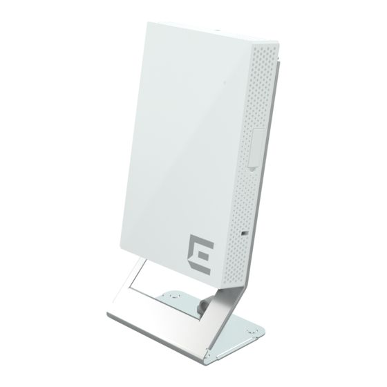
Install the Access Point Install the Access Point on a Desk Stand 8. Using a security torx T-8 or a VT-8 screw, secure the bracket locking tab for physical security. Figure 13: Security torx screw installation to the access point Install the Access Point on a Desk Stand Install the access point on a desk stand using the DSKSTD accessory. - Page 32 Install the Access Point on a Desk Stand Install the Access Point • One flat head T8 security torx M2.5×6.5 mm long locking screw • Two Phillips flat head M3.5×12 mm long self-tapping wood screws, if you want to fix the desk stand in place Note Provide your own torx screwdriver.
- Page 33 Install the Access Point Install the Access Point on a Desk Stand 3. Line up the access point on the mounting tabs of the desk stand. Figure 15: Access point alignment for installation on a desk stand 4. Slide the access point on the desk stand until it is fully seated and lock it in place. ExtremeWireless™...
- Page 34 Install the Access Point on a Desk Stand Install the Access Point 5. Attach the security locking tab screw to the security locking tab on the desk stand, and lock the access point in place. Figure 16: Access point security screw installation on a desk stand 6.
-
Page 35: Ge And Console Connections
GE and Console Connections The AP302W access point has four GE (Ethernet) ports and a Console port. During administration and maintenance through the Console, the access point must still have a power connection through either an Ethernet PoE cable or an external DC power supply. For more information, see AP302W Power Source on page 15. -
Page 36: Internal Antenna Configuration
Internal Antenna Configuration Table 10: Antenna configuration for AP302W access point Software mode Radio 1 Radio 2 Description Mode 1 2.4 GHz 5 GHz - full Dual-band dual concurrent Mode 2 2 GHz/5 GHz - full 5 GHz - full R1 unlocked sensor Mode 3 5 GHz - low... -
Page 37: Specifications
Specifications AP302W access point physical and environmental specifications. Table 11: Physical specifications Specification Description Dimensions 6.8in. × 4.2in. × 1.1in. (175 mm × 106 mm × 29 mm) Weight 0.95 lbs. Housing Plastic Radios Two 802.11ax radios (one 2X2 2.4GHz and 5 GHz radio, and one 2X2 5 GHz radio) AP302W Power Source on page 15... -
Page 38: Regulatory And Compliance Information
Regulatory and Compliance Information Safety Guidelines on page 38 Maximum Permissible Exposure (MPE) Statement for Mobile Devices on page 39 FCC Declaration of Conformity Statement on page 39 Industry Canada Notice on page 40 Australia Notice on page 41 Japan Indoor Use Statement on page 41 Brazil Agência Nacional De Telecomunicações (Anatel) Statement on page 41... -
Page 39: Maximum Permissible Exposure (Mpe) Statement For Mobile Devices
Maximum Permissible Exposure (MPE) Statement for Regulatory and Compliance Information Mobile Devices Maximum Permissible Exposure (MPE) Statement for Mobile Devices Exposure limit for mobile devices set forth by European Union. This equipment complies with EU radiation exposure limits set forth for an uncontrolled environment. This equipment should be installed and operated with a minimum distance of 23 cm between the radiator and your body. -
Page 40: Industry Canada Notice
This radio transmitter [IC: 4141B-AP302W] has been approved by Innovation, Science and Economic Development Canada to operate with the antenna types listed in ExtremeWireless AP302W Access Point Installation Guide, with the maximum permissible gain indicated. Antenna types not included in this list that have a gain greater than the maximum gain indicated for any type listed are strictly prohibited for use with this device. -
Page 41: Australia Notice
Regulatory and Compliance Information Australia Notice Australia Notice AU co-location MPE Statement This equipment complies with AU radiation exposure limits set forth for an uncontrolled environment. This equipment should be installed and operated with minimum distance of 24 cm between the radiator and your body. -
Page 42: Supplement To Product Instructions
Supplement to Product Instructions Regulatory and Compliance Information Supplement to Product Instructions National Communications Commission (NCC) Statement Details about NCC statement. ExtremeWireless™ Access Point AP302W... -
Page 43: Ce Information
Regulatory and Compliance Information CE Information CE Information The device is restricted to indoor use only when operating in the 5150 to 5350 MHz frequency range. Warning CE co-location MPE Statement: This equipment complies with CE radiation exposure limits set forth for an uncontrolled environment. -
Page 44: Declaration Of Conformity In Languages Of The European Community
Declaration of Conformity in Languages of the European Community Regulatory and Compliance Information In accordance with Directive 2012/19/EU of the European Parliament on waste electrical and electronic equipment (WEEE): 1. The symbol above indicates that separate collection of electrical and electronic equipment is required. - Page 45 Declaration of Conformity in Languages of the Regulatory and Compliance Information European Community Swedish Härmed intygar att radioutrustningstypen AP302W överensstämmelse med de väsentliga egenskapskrav och övriga relevanta bestämmelser som framgår av direktiv 2014/53/ EU. För fullständig text av EU-försäkran om överensstämmelse, kontakta Extreme regelefterlevnad på...
- Page 46 Declaration of Conformity in Languages of the European Community Regulatory and Compliance Information Portuguese declara que este Radio LAN device (AP302W) está conforme com os requisitos essenciais e outras disposições da Directiva 2014/53/EU. Para o texto integral da declaração de conformidade da UE, contacte a conformidade regulamentar extrema em compliancerequest@extremenetworks.com...
-
Page 47: Index
Index access point installation Japan indoor use regulatory statement 41 desk stand install 16 junction box install junction box install 16 EU junction box 25 wall install 16 extension bracket 25 access point overview 9 USA junction box 25 Australia notice 41 wall plate bracket 25 box contents light sensor 15 ACC-BKT-AX-WP-DSKSTD accessory 16–18 ACC-BKT-AX-WP-EXT accessory 16–18 access point box contents 16–18... - Page 48 Index technical support contacting 7 wall install ACC-BKT-AX-WP-EXT accessory install with in-box wall plate bracket 19 flat surface install 19 in-box wall plate bracket 19 warnings 5...
Need help?
Do you have a question about the ExtremeWireless AP302W and is the answer not in the manual?
Questions and answers