Extreme Wireless AP3000X - Indoor Access Point Quick Reference
- Installation manual (47 pages)
Advertisement
- 1 Scan to Download the ExtremeCloud IQ Companion Mobile Application
- 2 Scan for Product Support Details
- 3 Overview
- 4 Status LED Activity Description
- 5 Box Contents
- 6 Install the Device
- 7 Lock the Device after Installation
- 8 External Antenna Information
- 9 Professional Installation Instruction
- 10 Documents / Resources
Scan to Download the ExtremeCloud IQ Companion Mobile Application
Commission, monitor, and troubleshoot devices easily with ExtremeCloud IQ Companion Mobile Application (supported on iOS and Android).
Use your mobile device camera to scan the serial number, capture installation images, assign or change device location, and network policy. The ExtremeCloud IQ Companion Mobile Application enables you to access the device CLI for troubleshooting and view device and client status
ExtremeCloud IQ Companion iOS Mobile Application


ExtremeCloud IQ Companion Android Mobile Application


Scan for Product Support Details
ExtremeCloud IQ Companion Mobile Application Onboarding

Overview
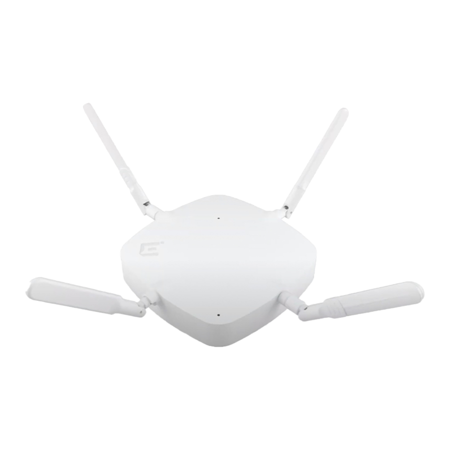
The AP3000X access point is an indoor model 802.11ax Wi-Fi 6E access point with external antennas. Out of the four external antennas on the unit, two 6G external antennas come built-in attached to the unit and cannot be removed.
The other two 2.4G/ 5G antennas are in the box.
For information on antennas that can be purchased separately, see "External Antenna Information".
The AP3000X can be mounted on a flat surface such as a wall, solid flat ceiling, to a junction box or a gang box, and can be installed on a suspended ceiling or a drop ceiling.
The AP3000X access point has the following features:
- Radios:
- Two 802.11ax radios (one 2X2 2.4GHz and 6 GHz radio, and one 2X2 5 GHz radio)
- One IoT Radio (2.4 GHz)
- Console port: Micro USB
- Two Ethernet ports (Eth0 and Eth1)
- Eth0: 2500/1000/100 Mbps auto-negotiation Ethernet port, RJ45, Power over Ethernet (PoE) at 802.3at
- Eth1: 1000/100/10 Mbps, RJ45
- One multicolor status light
- One reset button
- One Kensington lock
- One USB 2.0 type A connector
- Power: PoE 802.3af and 802.3at (see Table 1 for details) Antennas: two external omni-directional 2.4G/5G dual-band antennas, two 6G nonremovable antennas, and one Bluetooth Low Energy (BLE) antenna
- Temperature: -20°C to +55°C (-4°F to +131°F)
- Enclosure: Plastic
AP3000X Power source
| Power source | Description |
| Power over Ethernet (PoE) | Power is provided through the 2.5G Ethernet port of AP3000X, compliant to be powered with 802.3af and 802.3at to provide full functionality. For reduced functionality, use 802.3af. |
| External 12V DC power supply (optional; ordering part #37215- PWR 12VDC/2A, 2.5mm x 5.5mm connector) | Power is provided through an external DC power supply plugged into an AC source. |

AP3000X access point hardware components
Side ports on the AP3000X access point
| Callout | Description |
| 1 | Kensington security slot |
| 2 | USB port |
| 3 | Console port |
| 4 | 12VDC power |
| 5 | ETH1 |
| 6 | ETH0 and PoE+ |
Status LED Activity Description
The AP3000X access point has one status light on top of the chassis that shows operational states for system power, firmware updates, Ethernet and wireless interface activity, and major alarms.
- Steady white: The device has successfully established a Control And Provisioning of Wireless Access Points (CAPWAP) connection to ExtremeCloud IQ and is operating normally.
- Slow-blinking white: The device has a CAPWAP connection to ExtremeCloud IQ but is operating on 802.3af power instead of 802.3at power.
- Steady amber: The device is initializing, rebooting, or is running without a CAPWAP connection.
- Slow-blinking amber: The device has no CAPWAP connection to ExtremeCloud IQ and is operating on 802.3af power instead of 802.3at power.
- Fast-blinking amber: The device is upgrading its IQ Engine firmware.
- Dark: power is off.
Box Contents
Ensure that the following items are available:
Contents of the AP3000X Box
| Quantity | Item |
| 1 | AP3000X access point |
| 1 | AP3000X Quick Reference |
| 1 | AH-ACC-BKT-AX-TB mounting bracket |
| 2 | Phillips pan head wood screws |
| 2 | Screw-in anchors |
| 2 | 2.4 GHz/5 GHz external antennas |
All optional brackets and accessories are sold separately. For installation instructions about all mounting procedures, see ExtremeWireless Access Point AP3000X Installation Guide in the Extreme Networks Documentation Support site.
Install the Device
 Electrical Hazard: Only qualified personnel should perform installation procedures.
Use these instructions as guidelines for mounting and connecting the AP3000X access point easily and safely. The AP3000X comes with the AHACC-BKT-AX-TB mounting bracket that can be used to mount the access point on flat surfaces such as solid flat ceilings or wood walls.
 Note: The mounting procedures for installing the access point to non-standard ceilings are covered in the ExtremeWireless Access Point AP3000X Installation Guide.
Install the Unit on a Wall or a Flat Ceiling
Use the AH-ACC-BKT-AX-TB mounting bracket for flat surface wall or solid ceiling installation.
Pre-installation checklist:
The following hardware is required for installing the AH-ACC-BKT-AX-TB accessory on a wall or a solid ceiling:
- An AP3000X access point
- One AH-ACC-BKT-AX-TB mounting bracket
- Two M3.5 pan head wood screws and two screw-in anchors
Note: The wood screws and screw-in anchors come in a separate plastic bag.
- Using the AH-ACC-BKT-AX-TB mounting bracket as a template, mark and drill two mounting holes.
- Attach the bracket to the wall using two M3.5 pan head wood screws. Use push-in anchors or screw-in anchors for drywall or plastic board installations on vertical walls.
Note: Screw-in anchors must be used for ceiling installations.
- Attach the AP to the bracket. Align the red dot on the bracket and the AP.
- Press and rotate the access point 1/8 turn clockwise until it clicks into place.
Note: For wall installation, the 'E' logo must be on the left side of the access point as shown in Figure 3.
- Attach the Cat5e RJ45 cable to the ETH0 port on the access point.
Install the Unit on a Non-Standard Ceiling Grid or a Wall
For non-standard ceiling grid installation or wall installation instructions, see Wi-Fi 6 802.11ax Access Points Accessories Guide.
The AP can be installed on a non-standard ceiling grid with the following accessories:
Non-standard ceiling grid and wall accessories information
| Bracket part number | Description |
| AH-ACC-BKT-AX-TB | Mounting bracket for Prelude ceilings (15/16 in. ceiling grid), Suprafine ceilings (9/16 in. ceiling grid), and walls. The ceiling tile sides must be flat |
| AH-ACC-BKT-AX-IL | Mounting bracket for Interlude (9/16 wide T-bar with protrusion) ceilings |
| AH-ACC-BKT-AX-SL | Mounting bracket for Silhouette ceilings (ceiling grid with 1/8 in. or 1/4 in. bottom opening) |
| ACC-BKT-AX-JB | Junction box or wall mounting for indoor APs. |
| ACC-BKT-AX-BEAM | Beam mounting for indoor access points |
| AH-ACC-BKT-AX-WL | Mounting bracket for direct-to-wall installations when a 1.25 inches of space is desired between the wall and the access point |
Note: The default bracket for wall installation is the ACC-BKT-AX-JB bracket. Order the -JB bracket for new wall installations. The AH-ACC-BKT-AX-WL bracket is for users who already have the -WL brackets.
Lock the Device after Installation
Use the Kensington slot on the side of the AP to secure it. The slot prevents someone from removing the AP from the mounting accessory.
External Antenna Information
The AP3000X access point comes with four external antenna connectors. It is compatible with the ML-2452-APA2-02 and ML-2452-HPAG5A8-01 antennas.
Note: The ML-2452-APA2-02 and ML-2452-HPAG5A8-01 antennas are purchased separately.
The ML-2452-HPAG5A8-01 antenna requires the 25-85392-01R adapter for mounting.

AP3000X external antenna port connectors
AP3000X external antenna ports radio information
| Radio modes | Antenna ports | |
| Radio port (2.4G/5G) | Radio port (6G) | |
| 1 | 2.4G and 5G | - |
| 2 | 5G | 6G |
AP3000X radio ports support information
| Radio port | Antenna type |
| 2.4 GHz/5 GHz | Dual-band omni |
| 6 GHz | Omni |
Note: For antenna specifications and installation information, see the Wi-Fi 6 (802.11ax) Antenna Specifications Guide.
Professional Installation Instruction
Installation personnel
This product is designed for specific application and needs to be installed by a qualified personnel who has RF and related rule knowledge. The general user shall not attempt to install or change the setting.
Installation procedure
Refer to the ExtremeWireless Access Point AP3000X Installation Guide.

Select the installation position and ensure that the final output power does not exceed the limit set forth in relevant rules. The violation of the rule could lead to serious federal penalty.

Documents / Resources
References
Download manual
Here you can download full pdf version of manual, it may contain additional safety instructions, warranty information, FCC rules, etc.
Download Extreme Wireless AP3000X - Indoor Access Point Quick Reference
Advertisement


Need help?
Do you have a question about the Wireless AP3000X and is the answer not in the manual?
Questions and answers