Sign In
Upload
Manuals
Brands
Ricoh Manuals
Printer Accessories
CH-C1
Ricoh CH-C1 Manuals
Manuals and User Guides for Ricoh CH-C1. We have
4
Ricoh CH-C1 manuals available for free PDF download: Field Service Manual, System Maintenance, Technical Bulletin, Service Training
Ricoh CH-C1 Field Service Manual (1612 pages)
Brand:
Ricoh
| Category:
Printer
| Size: 49.68 MB
Table of Contents
Section 1
14
Revision History
3
Revision History (V2.00)
3
Revision History (V3.00)
6
Important Safety Notices
9
Prevention of Physical Injury
9
Health Safety Conditions
9
Observance of Electrical Safety Standards
9
Safety and Ecological Notes for Disposal
10
Laser Safety
10
Warnings, Cautions, Notes
11
Symbols, Abbreviations and Trademarks
12
Trademarks
12
Table of Contents
14
Product Information
45
Product Overview
45
Component Layout
45
Paper Path
46
Drive Layout
47
Machine Codes and Peripherals Configuration
50
Specifications
56
Guidance for those Who Are Familiar with Predecessor Products
57
New Features of D137/D138 and D135/D136
57
Developed Image Quality
57
Improvement of Banding Issues
57
Improvement of the Scratch Mark Issue
58
Improvement of the Toner Dusting Issue
58
Developed Printing Quality of Textured Paper
59
Developed User Appliance
59
Controller Features
60
Installation
61
Installation Requirements
61
Environment
61
Minimum Space Requirements
62
Installation Space
62
Dimensions
63
D137/D138
63
D135/D136
64
Power Requirements
64
Input Voltage Level (D137/D138)
64
Input Voltage Level (D135/D136)
65
Main Machine Installation
66
Special Tools and Lubricants
66
D137/D138
66
D135/D136
67
Installation Flow Chart
68
Accessory Check
69
D137/D138
69
D135/D136
71
Installation Procedure (D137/D138)
74
Removing the Retainers of the Charge Roller Units (C, M, K)
76
Attaching the ITB Separation Lever
84
Operation Panel Attachment
89
Operator Call Light Attachment
95
Attaching the Service Pocket
96
Storing the Supply Port Caps for the Developer
98
Storing the Factory SP Sheet
99
Attaching the Decals
99
Machine Level Adjustment
101
Installing the Securing Bracket to Prevent the Power Cord from Falling off
103
How to Set the Toner Cartridge
104
Executing DEMS
106
ACC (Automatic Color Calibration) Adjustment
106
Checking the Copy Image with Color Chart
107
Paper Tray Settings
107
Paper Library Data Installation
107
Installation Procedure (D135/D136)
109
Removing the Retainers of the Charge Roller Units (C, M, K)
112
Attaching the ITB Separation Lever
120
Attaching the Service Pocket
125
Storing the Supply Port Cap of the Developer
127
Storing the Factory SP Sheet
127
Attaching the Decals
127
Machine Level Adjustment
129
Installing the Securing Bracket to Prevent the Power Cord from Falling off
131
How to Set the Toner Cartridge
132
ACC (Automatic Color Calibration) Adjustment
133
Checking the Copy Image with the Color Chart
134
Paper Tray Settings
134
Security Function Installation
134
Moving the Machine
143
D137/D138
143
D135/D136
145
Finisher SR4090 (D703) /Booklet Finisher SR4100 (D704)
147
Accessory Check
147
Installation Procedure
148
Auxiliary Trays
155
Output Jogger Unit Type M2 (D705)
158
Component Check
158
Installation
158
Punch Unit PU3060 (D706)
163
Accessory Check
163
Installation Procedure
164
Finisher SR4110 (D707)
187
Accessories
187
Installation Procedure
188
Docking the Finisher D707
190
Connecting the Finisher D707
192
How to Use the Spacer to Correct Paper Skew
193
SP Setting
196
Punch Unit PU5000 (B831)
197
Component Check
197
Installation Procedure
198
Cooling Fan Unit Type M2 (D770)
204
Component Check
204
Common Installation Procedure for Finisher SR4090 / Booklet Finisher SR4100 and Finisher SR4110
205
Installation Procedure for Finisher SR4090/ Booklet Finishersr4100
214
Installation Procedure for Finisher SR4110
220
Information for Cooling Fan Unit Type M2
233
Copy Tray Type M2 (D744)
235
Component Check
235
Installation Procedure
236
Decurl Unit DU5020 (D727) (D137/D138 Only)
251
Accessories
251
Installation Procedure
252
Connect the Downstream Peripheral Device
260
Paper Curl Adjustment When Decurl Unit DU5020 Connects with Finisher SR4090 or Booklet Finisher SR4100
263
Buffer Pass Unit Type 5020 (D751) (D137/D138 Only)
264
Accessory Check
264
Installation
265
01: When Connecting the Buffer Pass Unit with the Mainframe
268
02: When Connecting the Buffer Pass Unit with the Decurl Unit DU5020 (D727)
273
Common Procedure
278
Multi-Folding Unit FD4000 (D615)
284
Accessories
284
Installation
285
Tapes
285
Paper Guide, Sponge Strip
286
Ground Plate
288
Docking
288
Power Cord
290
Height Adjustment
291
Removing Parts for the Cover Interposer Tray CI4020 (D712)
292
Proof Tray Auxiliary Plate
293
Detecting Paper Skew
293
Correcting Skew
294
Checking Side-To-Side Registration
296
Correcting Side-To-Side Registration
296
Mail Box CS4010 (D708) (D135/D136 Only)
298
Accessories
298
Installation Procedure
298
Cover Interposer Tray CI4010 (D711)
304
Accessories
304
Installation Procedure
305
Cover Interposer Tray CI4020 (D712)
322
Accessories
322
Installation Procedure
323
Setting up the Unit and Docking to the Copier
323
Docking the Next Peripheral Device
326
Mounting the Tray Unit
326
Lcit Rt4020 (D709)
330
Accessories
330
Installation Procedure
330
Adjustment for the Rubber Foot Positions on the Rail
338
LCIT (D709) Tray Heater
340
Accessories
340
Installation
341
Image Adjustments: Side-To-Side Registration
354
1/2" X 14" Paper Size Tray Type M2 (D745)
356
Component List
356
Installation Procedure
357
Lcit Rt4030 (D710)
365
Accessory Check
365
Installation Procedure
365
How to Disconnect the LCIT from the Main Machine
376
LCIT (D710) Tray Heater
378
Accessories
378
Installation
379
Image Adjustments: Side-To-Side Registration
385
A3/11"X17" Tray Unit Type M2 (D749)
386
Component List
386
Installation
387
Copy Connector Type 3260 (B328)
394
Accessory Check
394
Preparation
394
Installation
395
Tab Sheet Holder Type M2 (D750)
401
Accessories
401
Installation
401
Ieee802.11A/G/N Unit Type M2 (D164)
405
Component List
405
Installation Procedure
405
User Tool Settings for IEEE 802.11A/G/N
408
SP Mode Settings for IEEE 802.11 Wireless LAN
410
Bluetooth Interface Unit Type D (D566)
411
Accessories
411
Installation Procedure
411
IEEE1284 Interface Board Type a (B679)
413
Component List
413
Installation Procedure
413
File Format Converter Type E (D377)
415
Component List
415
Installation Procedure
415
SD Card for Netware Printing Type M2 (D719)
417
Component List
417
Installation Procedure
417
OCR Unit Type M2 (D166)
419
Accessories
419
Details about Searchable PDF
419
Installation Procedure
420
Restoration Procedure
422
Postscript3 Unit Type M2 (D719)
423
Accessories
423
Installation Procedure
423
IPDS Unit Type M2 (D719)
425
Accessories
425
Installation Procedure
425
Browser Unit Type M2 (D719)
427
Accessories
427
Installation Procedure
427
Do the Following Steps if the Customer Is Using the Ricoh Javascript Connected to a Web Application Developed by Operius/Ridp
429
Optional Counter Interface Unit Type a (B870)
430
Component Check
430
Installation Procedure
430
Smart Card Reader Built-In Unit Type M2 (D739) (D135/D136 Only)
434
Component Check
434
Installation Procedure
435
Dataoverwritesecurity Unit Type H (B869) (D135/D136 Only)
443
Overview
443
Component List
443
Installation Procedure
443
Copy Data Security Unit Type G (D640)
445
Component Check List
445
Installation
445
User Tool Setting
446
Check All Connections
447
SD Card Appli Move
448
Overview
448
Move Exec
448
Undo Exec
449
Caution
450
Preventive Maintenance
453
Preventive Maintenance Tables
453
Image Quality Standards
454
Resolution
454
Color Shift
454
Magnification Ratio Error Margin
455
Magnification Ratio Error Margin Deviation
455
Pitch Error Margin
455
Perpendicularity
456
Linearity
456
Parallelism
456
Missing Image Area (D135/D136)
457
Missing Image Area (D137/D138)
458
Margin Position
461
1St Side/2Nd Side Positional Precision (Shift Length of 2Nd Side Compared to 1St Side)
461
Paper Transfer Quality Standards
462
Registration
462
Exposure Glass
462
Adf
462
Skew
463
Exposure Glass
463
Adf
463
PM Parts Settings
465
PM Parts Replacement Procedure
465
Preparation before Operation Check
467
Operation Check
467
PM Counter Display
468
Note Concerning Running Distance Data
468
Opening the PM Counter
469
PM Parts Screen Details
470
All PM Parts List: Main Menu
470
Number Button Submenu
471
Parts List for PM Yield Indicator
471
Estimated Usage Rate/Estimated Remaining Days
472
Commissioning Status Report Print
473
Initial Adjustment SP Lists
474
D137/D138
474
D135/D136
478
Cleaning Points
481
Scanner
481
Exposure Glass, ADF Exposure Glass, Reflective Plate, 1St Mirror, 2Nd Mirror, 3Rd Mirror, Original Size Sensors
481
Laser Unit
483
Toner Shield Glass
483
Developer
484
Development Unit
484
Toner Supply
485
Toner Supply Unit
485
ITB Unit
486
Rollers
487
ID Sensor
487
Fusing
488
Stripper Plate (Fusing / Pressure)
488
Fusing Entrance Guide
489
Thermistor (Fusing Belt)
489
Thermistor (Hot Roller Shaft) (Proc5100S/5110S Only)
490
Thermopile
490
Other
491
Development Intake Dust Filter
491
Pressure Roller Dust Filter (D137/D138 Only)
491
Paper Feed
492
1St to 4Th Transport Roller (Drive/Idle)
492
Registration Roller (Drive/Idle)
493
Relay Roller (Drive/Idle)
494
Bypass Relay Roller (Drive/Idle)
495
Registration Sensor
496
Relay Sensor
496
Paper Dust Collection Unit
497
Duplex
499
Heat Pipe Roller
499
Heat Pipe Drive Roller
499
Paper Exit Roller (Drive/Idle)
500
Inverter Feed out Roller (Drive/Idle)
502
Inverter Exit Roller (Drive/Idle)
503
Paper Exit Relay Roller (Drive/Idle)
504
Inverter Feed in Roller (Drive/Idle)
506
Exit Transport Guide Plate (Upper/Middle/Left)
507
Duplex Unit Roller 1St to 4Th (Drive/Idle)
509
Duplex Exit Roller (Drive/Idle)
511
Transport Guide Plate (Upper/Lower)
512
Purge Guide Plate (Lower)
514
Lubrication Points
516
Fusing
516
Bearing (Hot Roller/Pressure Roller) Lubrication
516
Fusing Gear Lubrication
516
Replacement and Adjustment
519
Notes on the Main Power Switch
519
Push Switch
519
Characteristics of the Push Switch (DC Switch)
519
Shutdown Method
520
Forced Shutdown
521
Special Tools and Lubricants
522
D137/D138
522
D135/D136
522
Outer Covers
524
Right Cover
524
Right Middle Front Cover (D137/D138)
524
Right Middle Front Cover (D135/D136)
526
Right Middle Upper Cover (D137/D138)
527
Right Middle Upper Cover (D135/D136)
529
Right Middle Rear Cover (D137/D138)
530
Right Middle Rear Cover (D135/D136)
531
Right Lower Cover
532
Left Cover
534
Left Middle Cover
534
Left Lower Cover
537
Rear Cover
539
Rear Middle Cover
539
Rear Lower Cover
540
Upper Cover
541
Upper Front Cover (D137/D138)
541
Upper Front Cover (D135/D136)
542
Upper Rear Cover (Small)
544
Upper Left Cover/ Upper Right Cover
544
Operation Panel (D137/D138)
547
Operation Panel
547
LDCD Board
548
OPU Board / OPR Board
549
LCD Board (Touch Panel Unit)
551
Operation Panel (D135/D136)
553
Operation Panel
553
Touch Panel Calibration
554
LDCD Board
557
OPU Board / OPR Board
558
LCD Board (Touch Panel Unit)
559
Adf
560
ADF Removal
560
Adjustment after Replacing the ADF
562
CIS RGB Adjustment
562
Checking the Vertical Registration
562
Checking the Horizontal Registration
563
Checking the Skew
563
Checking the Magnification
564
Platen Adjustment
564
ADF Cover
565
ADF Front Cover
565
ADF Rear Cover
567
Feed Cover
568
Original Feed Unit
568
Pick-Up Roller / Transport Belt
569
ADF Separation Roller
572
Original Registration Sensor
573
Original Exit Sensor
574
ADF Control Board
576
Separation Sensor / Skew Correction Sensor
577
Original Width Sensor / Interval Sensor
578
B5 Width Sensor / A4 Width Sensor / LG Width Sensor
579
APS Feeler
580
ADF Lift-Up Interlock SW / Lift-Up Sensor
581
Original Set Sensor
582
A4 LEF/LT LEF Sensor
583
Bottom Plate HP Sensor
583
Bottom Plate Position Sensor
584
ADF Feed Cover Interlock SW / Pick-Up Roller HP Sensor
585
ADF Entrance Motor
586
ADF Scanning Motor
587
ADF Exit Motor
587
ADF Bottom Plate Lift Motor
588
ADF Pick-Up Roller Lift Motor / ADF Transport Motor
589
ADF Feed Motor
591
CIS Unit
592
Drawer Unit
594
Layout (Motors)
594
Drawer Unit (Front)
594
Drawer Unit (Rear)
595
Layout (Boards)
595
Drawer Unit Cover
596
If the Drawer Is Locked
597
DUB (Drawer Unit Board)
602
Paper Separation AC Power Pack
602
Fusing Web Control Board-Drawer (D137/D138 Only)
603
Curled Cord
604
Drawer Unit Connector
606
Drawer Unit Set Sensor
608
Drawer Unit Lock Sensor
608
Drawer Unit Handle Sensor
610
Drawer Unit Lock Motor
611
Registration Motor
613
Exit Motor
614
Duplex Inverter Entrance Motor
614
Exit Inverter Motor
615
Duplex Transport Motor
616
Duplex Exit Motor
617
Cleaning Web Motor (D137/D138 Only)
618
Cleaning Web Contact Motor (D137/D138 Only)
619
Fusing Heat Pipe Cooling Fan
620
IH Coil Cooling Fan
622
Fusing Pressure Roller Intake Fan (D137/D138 Only)
623
Toner Supply Unit
626
ID Chip Connector Board (KCMY)
629
Toner Supply Unit Inner Cover
630
Sub Hopper Unit (KCMY)
631
Adjustment after Sub Hopper Unit (KCMY) Replacement
633
Toner End Sensor (KCMY)
634
Sub Hopper Motor (KCMY)
634
Toner Supply Board (TSB)
634
Toner Cartridge Guide
635
Toner Supply Motor (KCMY)
638
Scanner Unit
640
Exposure Glass
640
ADF Exposure Glass / Gap Sheet (D135/D136)
641
How to Remove the ADF Exposure Glass/Gap Sheet
641
How to Attach the ADF Exposure Glass/Gap Sheet
642
Modification Procedure for Original Transport
644
Replacing Parts of the ADF
644
Removing the Scanner Parts
646
Lens Block / Original Size Sensor
646
Adjustment after Replacing the Lens Block
648
Exposure Lamp (LED)
648
Scanner Drive Motor
650
Scanner HP Sensor
652
DF Position Sensor
653
SIO Board
655
Scanner Unit
657
Scanner Wire
662
Preparation for Replacing a Scanner Wire
662
Replacing the Scanner Wire
663
Preparation for Reassembling the Scanner Wire
665
Reassembling the Scanner Wire
666
Installing the Scanner Heater
667
Accessories
667
Installation
668
Magnification and Registration Adjustment
671
Sub Scan Magnification Adjustment
671
Sub Scan Registration Adjustment
671
Main Scan Registration Adjustment
672
Laser Unit
673
Before You Begin
673
Caution Decals
673
Laser Unit
674
Before Replacement
674
Replacement
674
How to Distinguish between the CK Laser Unit and YM Laser Unit
676
Notes on Installation of a New Laser Unit
678
Adjustment after Laser Unit Replacement
678
Laser Unit Cooling Fan (Left / Right)
679
Pcdu
682
Faceplate
682
Pcdu
683
Charge Roller Unit
685
Drum Cleaning Unit Removal
686
Notes on Replacing the Drum Cleaning Unit and Drum Cleaning Blade
690
OPC Drum
691
Attaching the New OPC Drum
691
Drum Cleaning Unit Internal Components
694
Separation of the Lubrication Unit and Cleaning Unit
694
Lubrication Unit
696
Cleaning Unit
700
Assembling the Cleaning Unit and Lubrication Unit with New Seals
701
Development Unit
704
Development Filter
706
Removing Old Developer
707
General
707
PART 1: Preparations for Developer Removal
707
PART 2: Developer Removal Procedure
709
Adding New Developer
712
Adding New Developer (Summary)
713
Adding New Developer and Adjustment
713
Image Transfer Belt Unit
720
ITB Unit Removal
720
ITB Replacement
721
Lubrication after Replacement
726
ID/MUSIC Sensors
727
ITB HP Sensor
728
PTR Separation Sensor
728
ITB Lift (YMC) Sensor
729
Image Transfer Roller (K)
730
Image Transfer Roller (YMC)
731
ITB Bias Roller
733
Transfer Power Pack/Separation Power Pack
738
TDRB (Transfer Drive Relay Board)
739
Anti-Condensation Heater
740
PTR Separation Motor
741
AC Transfer Power Pack (D137/D138 Only)
742
ITB Motor
743
ITB Drive Shaft Gear / Encoder Sensor
743
ITB Driven Shaft Encoder Sensor
746
ITB Cleaning Unit
748
ITB Cleaning Blade
749
ITB Lubricant Brush
750
ITB Lubricant Bar
752
ITB Lubricant Blade
753
ITB Cleaning Unit Set Sensor
753
ITB Paper Dust Cleaning Brush Roller
754
Lubrication after Replacement
757
Paper Transfer Roller Unit
759
Paper Discharge Plate
762
Paper Transfer Roller
762
Fusing Unit
764
Screw List
764
Removing the Fusing Unit
766
Fusing Heat Pipe
769
Fusing Unit Cover
770
Fusing Front / Rear Cover
770
Entrance Drawer Cover
770
Exit Drawer Cover
771
Fusing Upper Cover
772
Separation Unit
772
Fusing Unit Plate
774
IH Coil Unit
777
Fusing Cleaning Web Unit (D137/D138 Only)
779
Fusing Cleaning Web (D137/D138 Only)
781
Fusing Belt Smoothing Roller (D137/D138 Only)
785
Fusing Belt Smoothing Roller Contact Sensor (Pro C5100S/Pro C5110S)
787
Separating the Fusing Unit
787
Heating Roller, Fusing Roller, Fusing Belt
789
Pressure Roller Stripper Plate
796
Fusing Lamp
798
Pressure Roller
800
Thermistor (Fusing Belt)
803
Thermistor (Hot Roller Shaft)
804
Heating Roller Rotation Sensor
805
Pressure Roller Sensor (Rear)
806
Pressure Roller Sensor (Front)
807
Hot Roller NC Sensor
808
Thermopile (Pressure Roller)
809
Thermostat (Pressure Roller)
811
Fusing Paper Feed Sensor
812
Adjustment after Replacing the Fusing Paper Feed Sensor
813
Cleaning Web Set Sensor
814
Cleaning Web End Sensor
814
Cleaning Web Contact Sensor
815
Paper Transport Belt Unit
816
Paper Transport Belt
817
PTB Fans
817
PTB Sensor
818
PTB Unit Set Sensor
819
Tandem Tray
820
Left Tandem Tray / Right Tandem Tray
820
Feed Roller, Pick-Up Roller and Separation Roller
822
Paper Feed Unit for Tray 1
823
Rear Fence Home Position Sensor / Left Tray Paper Sensor
827
Rear Fence Return Sensor
828
Paper Height Sensors 1, 2, 3 / Tray down Sensor / Right Tray Set Sensor
830
Rear End Fence Closed Sensor
833
End Fence Rear Solenoid
836
Left Tray Lock Solenoid
838
Rear Fence Drive Motor
839
1St Tray Lift Motor
839
Paper Feed Section (Tray 2-3 / Vertical Transport)
841
Paper Tray
841
Feed Roller, Pick-Up Roller and Separation Roller
841
Paper Feed Unit
842
Pick-Up Solenoid
844
Transport Sensor
844
Paper Feed Sensor
845
Paper Tray Upper Limit Sensor / Paper End Sensor
845
Vertical Transport LED
846
Paper Size Sensors
848
Paper Tray Set Sensors
848
Paper Tray Lift Motor
849
Tray Heater
850
Upper Tray Heater
850
Lower Tray Heater
852
Tray Heater Setting
853
By-Pass Tray Unit (D137/D138)
855
By-Pass Tray Unit Removal
855
By-Pass Tray Unit Separation
857
By-Pass Pick-Up Roller / By-Pass Feed Roller / By-Pass Separation Roller
858
By-Pass Tray Paper End Sensor
859
By-Pass Paper Width Sensor
860
By-Pass Paper Length Sensor
861
By-Pass Tray Lower Limit Sensor
862
By-Pass Tray Lift Motor
862
By-Pass Tray Upper Limit Sensor / By-Pass Paper Feed Sensor
865
By-Pass Pick-Up Solenoid
867
By-Pass Tray Set Sensor
868
By-Pass Tray LED Connector (Red)
868
By-Pass Tray Unit (D135/D136)
870
By-Pass Tray Unit Removal
870
By-Pass Tray Unit Separation
872
By-Pass Pick-Up Roller / By-Pass Feed Roller / By-Pass Separation Roller
874
By-Pass Tray Paper End Sensor
875
By-Pass Paper Width Sensor
876
By-Pass Paper Length Sensor
877
By-Pass Paper Feed Sensor
878
By-Pass Pick-Up Solenoid
881
By-Pass Tray LED Connector (Red)
882
Paper Relay and Registration Section
884
Registration Unit
884
Relay Unit
886
Registration Sensor
888
Paper Type Sensor
890
Relay Sensor
891
By-Pass Tray Paper Type Sensor
891
Paper Exit and Duplex Unit
894
Paper Exit Unit
894
Paper Exit Sensor
896
Paper Exit Relay Sensor
897
Inverter Exit Sensor
898
Inverter Feed-In Sensor
899
Inverter Feed-Out Sensor
901
Inverter Junction Gate Home Position Sensor
902
Inverter Junction Gate Motor
902
Duplex Inverter Solenoid
903
Paper Exit Left Guide Plate Sensor
904
Paper Exit Upper Guide Plate Sensor
905
Duplex Unit
906
Purge Relay Sensor / Duplex Invert Sensor
906
Duplex Invert Solenoid
907
Duplex Unit Entrance Sensor
908
Duplex Unit Sensor 1
909
Duplex Unit Sensor 2
909
Duplex Unit Sensor 3
910
Duplex Unit Sensor 4
910
Duplex Exit Sensor
911
Horizontal Feed Guide Plate Open Sensor
911
Roller HP Sensor 1
912
Roller HP Sensor 2
913
Sensor Shift Motor
913
Edge Detection Unit
915
Edge Detection Sensor
916
Sensor Shift HP Switch
916
Roller Shift Motor 1 / Roller Shift Motor 2
917
Paper Purge Unit
919
Pcb: Lsb
921
Push Switch
922
Duplex Inverter Motor
923
Purged Paper Sensor
924
LED: Connecter: Red
925
Upper Guide Plate LED / Purge Door LED
926
Lower Guide Plate LED
926
Main Boards / HDD Unit
928
Layout
928
Controller Board
929
When Installing the New Controller Board
931
HDD Unit
932
After Installing the New HDD Unit
933
Disposal of HDD Unit
933
Reinstallation
933
Bcu
934
NVRAM Replacement Procedure
935
NVRAM on the Controller Board
935
NVRAM (EEPROM) on the BCU
939
Ipu
940
Iob
941
When Removing the Motors that Are Behind the IOB
942
Pfb
942
When Removing the Motors that Are Behind the PFB
943
IH Inverter
943
AC Drive Board
944
Notes on Replacing the AC Drive Board
944
Psu1 / Psu2
945
When Removing the Motors and Sensors that Are Behind the PSU1/PSU2
946
Potential Sensor Board
948
Combined High-Voltage Power Supply Board (Charge / Development) (KCMY)
949
Combined High-Voltage Power Supply Board (KC)
949
Combined High-Voltage Power Supply Board (MY)
950
Fusing Web Control Board-Main Machine (D137/D138 Only)
951
AC Drive Board Relay (D137/D138 Only)
951
Motors and Sensors
952
Layout (Motor)
952
Rear of the Machine (Top)
952
Rear of the Machine (Middle)
953
Rear of the Machine (Bottom)
954
Drawer Unit (Front)
955
Drawer Unit (Rear)
956
Drum Motor (KCMY) / Drum Encoder Sensor (KCMY)
956
Removing the Drive Exhaust Fan and the Potential Sensor Board
960
Drum HP Sensor (D137/D138 Only)
962
Drum Cleaning Motor (KCMY)
962
Removing the Drive Exhaust Fan and the Potential Sensor Board
964
Development Motor (KCMY)
965
Removing the Drive Exhaust Fan and the Potential Sensor Board
967
Development Roller HP Sensor (KCMY)
968
By-Pass Feed Motor/Relay Motor
968
PTR Motor / PTR Encoder Sensor
970
Paper Feed Motor/Transport Motor
972
1St Paper Feed Motor/1St Transport Motor
972
Vertical Transport Motor
973
2Nd Paper Feed Motor/2Nd Transport Motor, 3Rd Paper Feed Motor/3Rd Transport Motor.973
975
Fusing Drive Motor
976
Waste Toner Collection Motor
978
Removing the Waste Toner Collection Motor
978
Removing the Fusing Belt Smoothing Roller Drive Motor and the Bracket
981
Waste Toner Lock Sensor
982
Fusing Release Motor
983
Removing the Fusing Belt Smoothing Roller Drive Motor and the Bracket
985
Fusing Belt Smoothing Roller Drive Motor (D137/D138 Only)
986
Fusing Belt Smoothing Roller Contact Motor (D137/D138 Only)
988
Fans and Filters
990
Layout (Fans)
990
Layout (Filters)
994
Controller Exhaust Fan
994
Controller Intake Fan
995
Development Exhaust Fans (Right / Left)
996
Development Intake Fans (KCMY)
998
Drive Exhaust Fan
1000
Fusing Exit Exhaust Fan
1000
Fusing Pressure Roller Exhaust Fan (D137/D138 Only)
1000
Heat Pipe Panel Exhaust Fan
1002
Heat Pipe Panel Intake Fan
1003
PTR Fusing Exhaust Fan
1005
ITB Motor Cooling Fan
1006
Ozone Exhaust Fan
1007
Duplex Exhaust Fans (Front / Middle / Rear)
1008
IH Coil Power Cooling Fan
1009
ITB Cleaning Intake Fan
1010
ID Sensor Cleaning Fan
1011
PSU Fans (Right / Left)
1012
Deodorizing Filters (Large / Small)
1013
Dust Filters (Large / Small)
1014
Ozone Filters (Large / Small)
1015
Waste Toner Collection
1017
Waste Toner Bottle
1017
Waste Toner Bottle Unit
1018
Installing the Relay Duct
1020
Waste Toner Bottle Motor Sensor
1021
Waste Toner Full Sensor
1022
Waste Toner Bottle Set Sensor
1023
Waste Toner Transport Motor
1023
Waste Toner Upper Transport
1023
Waste Toner Vertical Transport
1024
Waste Toner Lower Transport
1026
Adjustment after Replacement
1027
Troubleshooting
1029
Service Call 101-195
1029
SC100 (Engine: Scanning)
1029
Service Call 202-286
1041
SC200 (Engine: Image Writing)
1041
Service Call 300-398
1054
SC300 (Engine: Charge, Development)
1054
SC300 (Engine: Development)
1064
Service Call 400-498
1077
SC400 (Engine: Around the Drum)
1077
SC300/400 (Engine: Transfer/Separation, Cleaning Etc.)
1082
Service Call 501-595
1109
SC500 (Engine: Paper Transport 1: Paper Feed, Duplex, Transport)
1109
SC500 (Engine: Paper Transport 2: Fusing, Etc.)
1134
SC500 (Engine: Paper Transport 3: Feed, Duplex, Transport, Fusing)
1158
SC500 (Engine: Others)
1165
Service Call 620-689
1166
SC600 (Engine: Communication and Others)
1166
SC600 (Controller)
1186
Service Call 700-780
1199
SC700 (Engine: Peripherals)
1199
Service Call 816-899
1253
SC800 (Controller)
1253
Service Call 900-998
1315
SC900 (Engine: Others)
1315
SC900 (Controller)
1317
Jam Detection
1324
Jam Displays
1324
Removing Jammed Paper
1325
Printer Engine Jam History
1325
How to Check
1325
Display
1326
Jam Codes and Position Codes
1326
Adf
1327
Main Machine
1327
Lcit Rt4020 (D709)
1330
Lcit Rt4030 (D710)
1331
Finisher SR4090 (D703)
1331
Booklet Finisher SR4100 (D704)
1333
Advertisement
Ricoh CH-C1 System Maintenance (870 pages)
Brand:
Ricoh
| Category:
Printer
| Size: 4.08 MB
Table of Contents
Revision History
3
Revision History (V2.00)
3
Table of Contents
4
1 Main SP Tables-3
7
SP3-XXX (Process)
7
2 Main SP Tables-4
93
SP4-XXX (Scanner)
93
3 Main SP Tables-5
191
SP5-009 to 721 (Mode)
191
SP5-722 to 998 (Mode)
279
4 Main SP Tables-6
363
SP6-XXX (Peripherals)
363
5 Main SP Tables-7
465
SP7-001 to 931 (Data Log)
465
SP7-932 to 988 (Data Log)
541
6 Main SP Tables-8
615
Keys and Abbreviations in Data Log 2
615
SP8-XXX (Data Log 2)
618
7 Input and Output Check
673
Input Check Table
673
Output Check Table
743
8 Printer SP Mode
807
Sp1-XXX
807
9 Scanner SP Mode
821
Sp1-XXX
821
SP2-XXX (Scanning-Image Quality)
824
10 Software Version up
827
Software Update
827
Software Update Procedure
827
Doing the Software Update Procedure
827
Errors During Firmware Update
831
Error Message Table
831
Updating the LCDC for the Operation Panel
832
Downloading Stamp Data
833
Updating Java VM
834
Creating an SD Card for Updating
834
Updating Procedure
834
List of Error Messages
835
Updating the EXJS
838
To Update EXJS
838
When Checking the Version of EXJS
840
Package Firmware Update (D135/D136 Only)
842
Overview
842
Immediate Update
843
Update at the Next Visit (Reserve)
846
How to Set the Machine to Download Firmware Later (RESERVE)
847
How to Check if the Firmware Downloaded with RESERVE
850
How to Install Firmware Downloaded with RESERVE
851
Update Via SD Card
854
11 NVRAM Data Upload/Download
857
Uploading Content of NVRAM to an SD Card
857
Downloading an SD Card to NVRAM
859
12 Address Book Upload/Download
861
Information List
861
Download
862
Upload
864
Ricoh CH-C1 Service Training (640 pages)
Brand:
Ricoh
| Category:
All in One Printer
| Size: 12.39 MB
Table of Contents
Service Training
2
Product Concept
4
Operation Panel
12
Possible Configurations
17
Service Training
28
Comparison with Existing Models
29
Service Training
41
New Features
42
Service Training
72
Power On/Off Timer
80
Pop-Up Windows
86
Capturing the Debug Logs
92
Service Training
95
Install the Toner Cartridges
103
Moving the Machine
106
Service Training
109
Buffer Pass Unit
117
Multi-Folding Unit
119
Service Training
130
Outline of the Procedure
132
Where Skew and Side-To-Side Registration Are Measured
133
Adjusting the Registration
136
Parts Replacement Schedule
142
Finishing the Job
147
Counter Reset
148
Lock Mechanism
168
Machine Layout
181
Paper Path
182
Drive Layout
183
Rear View
183
Important Notes
186
PCB Layout
188
Drawer Unit
190
Forced Shutdown
196
Controller Board
197
BCU Board
200
AC Drive Board
201
Pick-Up and Feed
213
Bottom Plate Lift
214
Original Separation
215
Skew Correction
216
Original Size Detection
217
Original Feed
218
Jam Detection
229
Anti-Condensation Heater
243
Replacement and Adjustment
244
Skew Correction
256
Image Position Correction
257
Temperature Monitoring
259
Remove Protective Materials
264
Charge Roller
275
Drum Drive
276
Drum Cleaning Unit
280
Lubricant Bar Replacement
287
Operation
289
Development Unit
291
Dust Collection
296
Replacement and Adjustment
302
Drum Cleaning Unit
312
Removing Old Developer
320
Drum Motor
326
Development Motor
329
Process Control
332
Drum Potential Sensor
334
Temperature/Humidity Sensor
337
Two Modes
351
Toner Supply Control
352
Toner Cartridge Drive
362
Double Shutter
363
Main Units
376
Paper Feed
382
Feed and Separation
383
Pick-Up Roller Mechanism
386
Anti-Condensation Heaters
388
Tandem Tray
391
Paper End Detection
401
Paper Size Detection
402
Adjusting Registration
433
ITB Drive
442
ITB Speed Control
448
Temperature Control
450
ITB Cleaning
453
Replacement and Adjustment
456
Replacement Procedures
460
Power Supply
467
Hot Roller
486
Possible Settings
501
Removing the Fusing Unit
516
Drive Components
524
Overall Layout
539
Optional Peripherals
545
General Layout
548
Advertisement
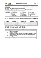
Ricoh CH-C1 Technical Bulletin (682 pages)
Brand:
Ricoh
| Category:
Printer Accessories
| Size: 39.18 MB
Table of Contents
Troubleshooting
25
Confirmation Method
46
Component Check
49
Installation Procedure
51
NVRAM Replacement Procedure
69
NVRAM on the Controller Board
69
Troubleshooting
79
Accessory Check
84
Installation Procedure
85
Troubleshooting
110
Installation Procedure
174
Supported Firmware
205
Troubleshooting
216
How to Adjust
229
Main Machine Installation
284
Special Tools and Lubricants
284
Installation Flowchart
285
CD-ROM-Driver
287
Moving the Machine
316
Troubleshooting
331
Sensor Locations
424
Stapler Unit
437
Booklet Stapler Unit
440
Press Folding Motor
442
Booklet Jogger Motor
446
Troubleshooting
455
PM Parts Settings
471
Operation Check
473
Important Notice
484
Installation Procedure
535
Production Line
595
Installation Space
655
Advertisement
Related Products
Ricoh Container Stacker
Ricoh CS4010
Ricoh CF5010
Ricoh Scan CX v1
Ricoh Ch-C1 Pro
Ricoh C231N - Aficio Color Laser Printer
Ricoh Aficio SP C820DNT2
Ricoh Aficio Color 4106
Ricoh Aficio C7521n
Ricoh C3210e
Ricoh Categories
All in One Printer
Printer
Digital Camera
Copier
Printer Accessories
More Ricoh Manuals
Login
Sign In
OR
Sign in with Facebook
Sign in with Google
Upload manual
Upload from disk
Upload from URL