Sign In
Upload
Manuals
Brands
Konica Minolta Manuals
Printer
bizhub 220
Konica Minolta bizhub 220 Manuals
Manuals and User Guides for Konica Minolta bizhub 220. We have
3
Konica Minolta bizhub 220 manuals available for free PDF download: Service Manual
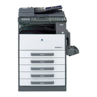
Konica Minolta bizhub 220 Service Manual (588 pages)
Brand:
Konica Minolta
| Category:
All in One Printer
| Size: 43.35 MB
Table of Contents
Field Service Total
2
Table of Contents
2
Safety and Important Warning Items
4
Important Notice
4
Description Items for Danger, Warning and Caution
4
Safety Warnings
5
Handling of Consumables
13
Internal Laser Radiation
16
Laser Caution Label
19
Laser Safety Label
19
Precautions for Handling the Laser Equipment
20
Warning Indications on the Machine
21
Measures to Take in Case of an Accident
22
Composition of the Service Manual
24
Notation of the Service Manual
25
General
28
Troubleshooting
32
1 System Configuration
36
Appendix General
36
2 Product Specification
38
Maintenance
39
Fax Kit (FK-506): (Option)
41
Maintenance
42
3 Periodical Check
42
Service Schedule
42
Main Body (Bizhub 163) /PF-502/MB-501
42
Main Body (Bizhub 211/220) /PF-502/MB-501
42
Maintenance Items
43
Parts to be Replaced by Users (CRU)
43
Periodical Parts Replacement/Cleaning 1 (Per 30,000-Original Feed)
43
Periodical Parts Replacement/Cleaning 2 (Per 40,000-Original Feed)
43
Periodical Parts Replacement/Cleaning 3 (Per 50,000-Original Feed)
44
Periodical Parts Replacement/Cleaning 4 (Per 80,000-Print)
44
Periodical Parts Replacement/Cleaning 5 (Per 120,000-Original Feed)
44
Periodical Parts Replacement/Cleaning 6 (Per 150,000-Print)
45
Periodical Parts Replacement/Cleaning 7 (Per 200,000-Original Feed)
45
Maintenance Parts
46
Replacement Parts
46
Cleaning Parts
48
Concept of Parts Life
49
Maintenance Procedure (Periodical Check Parts)
50
Cleaning of the Original Glass and Original Scanning Glass
50
Replacing the Separation Roller Assy
50
Replacing the Feed Roller
52
Replacing the Paper Dust Remover Assy
53
Replacing the Toner Bottle
53
Disassembly of the Imaging Unit
55
Replacing the Imaging Unit
55
Replacing the PC Drum
57
Replacing the Ozone Filter
58
Replacing the PC Drum Charge Corona Assy
59
Replacing the Cleaning Blade
59
Cleaning of the PC Drum Paper Separator Fingers
60
Cleaning of the Ds Collars
60
Cleaning of the Developer Scattering Prevention Plate
61
Replacing the Developer / Toner Agitating Seal
62
Cleaning of the Pre-Image Transfer Guide Plate
64
Replacing the Image Transfer Roller Assy
65
Replacing the Fusing Unit
65
4 Service Tool
67
Service Material List
67
CE Tool List
67
5 Firmware Upgrade
68
Preparations for Firmware Rewriting
68
Installing the Driver
68
Firmware Rewriting
70
Updating Method
70
Procedure When Upgrading the Firmware Has Failed
72
6 Other
74
Disassembly/Adjustment Prohibited Items
74
Adjustment/Setting
74
Disassembly/Assembly/Cleaning List (Other Parts)
75
Disassembly/Assembly Parts List
75
Cleaning Parts List
76
Disassembly/Assembly Procedure
77
Control Panel
77
Original Glass/Original Scanning Glass
77
Front Cover
78
Front Door
79
Paper Exit Cover
79
Tray 1
79
Left Cover
80
Paper Exit Tray
80
Rear Inside Cover
81
Upper Rear Cover
81
Left Rear Cover
82
Rear Cover
82
Right Rear Cover
82
Printer Control Board (PRCB)
83
Rear Right Cover
83
Right Cover
83
MFP Board (MFPB)
84
High Voltage Unit (HV1)
85
Power Supply Unit (DCPU)
86
Paper Size Detect Board (PSDTB)
88
Heater Relay Board (RYB): 200 V Areas Only
89
Pre-Image Transfer Register Board (PITRB)
89
Manual Bypass Tray
90
Toner Hopper Unit/Toner Replenishing Motor (M2)
90
PH Unit
92
Disassembly of the Fusing Unit
93
CCD Unit
96
Scanner, Exposure Lamp, and Inverter Board (PU2)
98
Scanner Motor (M4)
100
Scanner Drive Cables
101
Main Motor (M1)
111
Power Unit Cooling Fan Motor (FM2)
112
Fusing Cooling Fan Motor (FM1)
113
Paper Size Sensor (S5) Assy
114
Fusing Unit Interlock Switch (S2)
115
Flickerless Resistor (R1) (Only for 200 V Areas of Bizhub 163)
118
Inch/Metric Sensor/1 (PS7) Assy (3Rd Area Only)
118
Replacing the TCR Sensor (TCRS)
119
Application of Toner
120
Cleaning Procedure
121
Separation Roller
121
Feed Roller
122
Upper/Lower Synchronizing Rollers
122
Bypass Transport Roller/Roll
123
Paper Dust Remover
123
Lens
124
Mirrors
124
CCD Sensor
125
PH Window
126
Scanner Rails/Bearings
126
Charge Neutralizing Plate
127
Pre-Image Transfer Lower Guide Plate
127
Option Counter
128
Installation of the Key Counter
128
Adjustment/Setting
130
7 How to Use the Adjustment Section
130
8 Utility Mode
131
Utility Mode Function Tree
131
Utility Mode Function Setting Procedure
134
Changing the Setting Value in Utility Mode Functions
134
Exiting
134
Procedure
134
Setting in the Utility Mode
134
Machine Setting
134
Paper Source Setup
137
Custom Size Memory
138
User Management
138
Admin. Management
139
Copy Setting 1
141
Copy Setting 2
143
Dial Registration
144
Fax Registration
144
Fax Rx Operation
144
Fax Tx Operation
144
Reporting
144
Scan Setting
144
9 Adjustment Item List
145
10 Service Mode
148
10.1 Service Mode Function Setting Procedure
148
Changing the Setting Value in Service Mode Functions
148
Exiting
148
Procedure
148
10.2 Service Mode Function Tree
149
Maintenance
149
10.3 Setting in the Service Mode
152
Service's Choice
152
Adjust
161
Counter
167
Security Function Setting Procedure
179
CCD Unit Position Adjustment
182
Troubleshooting
188
Df-605/Mk
195
How to Reset
199
Power Supply Trouble
208
How to Identify Problematic Part
209
Image Quality Problem
209
Main Body
234
Parts Layout Drawing
234
Connector Layout Drawing
244
Timing Chart
245
General
254
General
258
1 Product Specifications
258
Maintenance
260
2 Firmware Upgrade
260
Preparations for Firmware Rewriting
260
Installing the Driver
260
Firmware Rewriting
262
Updating Method
262
Procedure When Upgrading the Firmware Has Failed
264
Adjustment/Setting
266
Disassembly/Assembly Parts List
267
Disassembly/Assembly Procedure
267
Disassembly/Assembly/Cleaning List (Other Parts)
267
Speaker
267
NCU Board
268
FAX Board
269
3 Other
266
Disassembly/Adjustment Prohibited Items
266
Adjustment/Setting
270
4 How to Use the Adjustment Section
270
5 Confirm Mode
271
Confirm Mode Function Tree
271
Confirm Mode Function Setting Procedure
271
Exiting
271
Procedure
271
Setting in the CONFIRM MODE
272
Total Page
272
Tx/Rx Result
272
Print Report
273
6 Utility Mode
275
Utility Mode Function Tree
275
Changing the Setting Value in Utility Mode Functions
276
Exiting
276
Procedure
276
Setting in the Utility Mode
276
Machine Setting
276
Admin. Management
277
Dial Registration
279
Fax Registration
280
Fax Tx Operation
280
Fax Rx Operation
281
Reporting
293
Utility Mode Function Setting Procedure
276
Pf-502
296
Changing the Setting Value in Service Mode Functions
295
Exiting
295
Procedure
295
Service Mode
295
Service Mode Setting Procedure
295
Maintenance
296
Service Mode Function Tree
296
Service's Choice
297
Setting in the Service Mode
297
Function
300
Factory Test
301
Softswitch
301
Clear Data
302
Soft Switch Set
304
Country for each Marketing Area
305
Default Setting
305
Default Soft Switch Setting for each Market Area 1
306
Default Soft Switch Setting for each Market Area 2
306
Default Soft Switch Setting for each Market Area 3
306
Default Soft Switch Setting for each Market Area 4
306
Soft Switch List
313
Soft Switch: #01
318
Soft Switch: #02
318
Soft Switch: #03
318
Soft Switch: #04
320
Soft Switch: #05
321
Soft Switch: #06
321
Soft Switch: #07
321
Soft Switch: #45
351
Soft Switch: #46
351
Soft Switch: #47
351
Soft Switch: #48
352
Soft Switch: #49
353
Soft Switch: #50
353
Soft Switch: #51
354
Soft Switch: #52
354
Soft Switch: #53
354
Soft Switch: #54
355
Soft Switch: #55
355
Soft Switch: #56
356
Soft Switch: #57
356
Soft Switch: #58
356
Soft Switch: #60
360
Soft Switch: #61
361
Soft Switch: #62
361
Soft Switch: #63
362
Soft Switch: #64
362
Fax Protocols
363
G3 ECM (G3 Error Correction Mode)
363
Line Control
364
Procedure of G3 Mode Communication
364
Table of Reference Code
365
How to Analyze the T30 Protocol Monitor
366
10. Fax Error
374
10.1 Communication Error
374
Error Occurring During Reception
374
Error Occurring During Transmission
374
Outline
374
Troubleshooting
374
10.2 Error Code
375
Reception
375
Transmission
377
Table of Contents
382
General
384
1 Product Specifications
385
Maintenance
388
2 Periodical Check
388
Maintenance Procedure (Periodical Check Parts)
388
Replacing the Pick-Up Roller and Feed Roller
388
Replacing the Separation Roller
389
Cleaning of the Pick-Up Roller, Feed Roller and Separation Roller
390
Cleaning of Miscellaneous Rollers
391
Cleaning of Miscellaneous Rolls
391
Cleaning of the Reflective Sensor Section
393
Cleaning of the Scanning Guide
393
3 Other
394
Adjustment/Setting
394
Disassembly/Adjustment Prohibited Items
394
Adf (Df-605)
396
Mount Kit (MK-501)
396
Main Control Board
399
Variable Resistor
399
Complete Stamp Unit 2
401
Replacing the Replace Stamp 2
402
4 Firmware Upgrade
403
Adjustment/Setting
404
5 How to Use the Adjustment Section
404
6 Service Mode
405
Changing the Setting Value in Service Mode Functions
405
Exiting
405
Procedure
405
Service Mode Function Setting Procedure
405
Service Mode Function Tree
405
Adjust
406
Setting in the Service Mode
406
Function
410
Clear Data
411
7 Mechanical Adjustment
412
Leading Edge Skew Adjustment
412
Troubleshooting
414
8 Jam Display
414
Initial Check Items
414
Sensor Layout
414
Solution
414
Misfeed at Paper Take-Up Section
415
Misfeed at Transport Section
416
Misfeed at Turnover Section
416
Misfeed at Paper Exit Section
417
General
422
Mb-501
422
9 Malfunction Code
418
C0044: ADF Cooling Fan Motor Failure
418
Solution
418
General
422
1 Product Specification
424
2 Periodical Check
426
Maintenance Procedure (Periodical Check Parts)
426
Pick-Up Roller/Feed Roller
426
Separation Roller
428
Cleaning of the Registration Rollers/Rolls
430
Cleaning of the Exit Rollers/Rolls
431
3 Other
434
Adjustment/Setting
434
Disassembly/Adjustment Prohibited Items
434
Document Feed Section Cover
437
Document Feeding Tray
437
Rear Cover
437
DF Control Board
439
Adjustment/Setting
440
4 How to Use the Adjustment Section
440
5 Service Mode
441
Changing the Setting Value in Service Mode Functions
441
Exiting
441
Procedure
441
Service Mode Function Tree
441
Service Mode Setting Procedure
441
Adjust
442
Setting in the Service Mode
442
Function
445
6 Mechanical Adjustment
446
ADF Height Adjustment
446
ADF Leading Edge Skew Adjustment
447
Troubleshooting
450
General
456
IC-206/Nc-503
456
7 Jam Display
450
Display Resetting Procedure
450
Misfeed Display
450
Sensor Layout
450
Initial Check Items
451
Misfeed at the Document Feed Section
451
Solution
451
Misfeed at the Document Transport Section
452
Misfeed at the Document Exit Section
453
General
456
1 Product Specifications
458
2 Periodical Check
460
Maintenance Procedure (Periodical Check Parts)
460
3 Other
461
Disassembly/Adjustment Prohibited Items
461
Cleaning Parts List
462
Disassembly/Assembly Parts List
462
Disassembly/Assembly/Cleaning List (Other Parts)
462
Disassembly/Assembly Procedure
463
Lower Right Cover
463
Right Cover
463
AD Drive Board
464
Transport Motor
464
Cleaning Procedure
465
Duplex Unit Transport Rollers/Rolls
465
Switch Back Unit Transport Rollers/Roll
465
Bypass Transport Roller/Rolls
466
Duplex Unit Ventilation Section
466
Adjustment/Setting
468
4 How to Use the Adjustment Section
468
5 Service Mode
469
Changing the Setting Value in Service Mode Functions
469
Exiting
469
Procedure
469
Service Mode Function Setting Procedure
469
Service Mode Function Tree
469
Service's Choice
469
Setting in the Service Mode
469
Troubleshooting
470
General
476
Sf-501
476
6 Jam Display
470
Misfeed Display
470
General
476
Maintenance
480
Misfeed Display Resetting Procedure
494
Troubleshooting
494
Sensor Layout
495
Solution
496
Initial Check Items
497
General
500
1 Product Specification
503
2 Periodical Check
504
Maintenance Procedure (Periodical Check Parts)
504
Replacing the Feed Roller
504
3 Other
507
Adjustment/Setting
507
Disassembly/Adjustment Prohibited Items
507
Tray
513
Cleaning Procedure
517
Feed Roller
517
Adjustment/Setting
520
4 How to Use the Adjustment Section
520
5 Service Mode
521
Changing the Setting Value in Service Mode Functions
521
Exiting
521
Procedure
521
Service Mode Function Tree
521
Service Mode Setting Procedure
521
Service's Choice
521
Setting in the Service Mode
521
6 Mechanical Adjustment
522
Troubleshooting
526
7 Jam Display
526
Misfeed Display
526
Sensor Layout
527
Initial Check Items
528
Solution
528
Js-503
500
Troubleshooting
532
1 Product Specification
535
2 Other
536
Disassembly/Assembly Parts List
537
Disassembly/Assembly Procedure
537
Disassembly/Assembly/Cleaning List (Other Parts)
537
JS Drive Board
537
Paper Detecting Board
540
Bin Switching Motor
542
3 Malfunction Code
544
Trouble Code
544
Troubleshooting
544
Trouble Code List
545
C0B60: bin Switching Motor Malfunction
547
Solution
547
Troubleshooting
550
1 Product Specifications
552
2 Periodical Check
554
Maintenance Procedure (Periodical Check Parts)
554
3 Other
555
Disassembly/Adjustment Prohibited Items
555
Disassembly/Assembly Parts List
556
Disassembly/Assembly Procedure
556
Disassembly/Assembly/Cleaning List (Other Parts)
556
Shift Motor
556
SF Drive Board
557
4 Malfunction Code
560
C0B80: Shift Motor Malfunction
560
Solution
560
Adjustment/Setting/Troubleshooting
564
1 Product Specifications
566
Network Printing (NC-503)
566
Printing (IC-206)
566
Scan to E-Mail/Scan to Server (FTP) (IC-206/NC-503)
566
2 Firmware Upgrade
568
Installing the Driver
568
Preparations for Firmware Rewriting
568
Firmware Rewriting
570
Updating Method
570
Procedure When Upgrading the Firmware Has Failed
572
3 Other
574
Troubleshooting
560
Disassembly/Adjustment Prohibited Items
574
Disassembly/Assembly Procedure
575
Image Controller/Network Interface Card
575
Adjustment/Setting
576
4 How to Use the Adjustment Section
576
5 Utility Mode
577
Utility Mode Function Tree
577
Changing the Setting Value in UTILITY MODE Functions
578
Exiting
578
Procedure
578
Utility Mode Function Setting Procedure
578
Admin. Management
579
Setting in the UTILITY MODE
579
Scan Setting
585
Troubleshooting
586
Troubleshooting Procedure Chart
586
Troubleshooting Procedure Overview
586
Advertisement
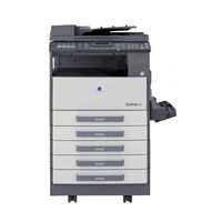
Konica Minolta bizhub 220 Service Manual (182 pages)
Brand:
Konica Minolta
| Category:
Printer
| Size: 7.98 MB
Table of Contents
Theory of Operation Total
2
Service Manual
1
Table of Contents
2
Safety and Important Warning Items
4
Important Notice
4
Description Items for Danger, Warning and Caution
4
Safety Warnings
5
Connection to Power Supply
7
Handling of Consumables
13
Internal Laser Radiation
16
Laser Caution Label
19
Laser Safety Label
19
Precautions for Handling the Laser Equipment
20
Warning Indications on the Machine
21
Measures to Take in Case of an Accident
22
Composition of the Service Manual
24
Notation of the Service Manual
25
Revision History
27
Outline/Composition/Operation
28
Outline
32
1 System Configuration
32
2 Product Specification
34
Fax Kit (FK-506): (Option)
37
3 Cross Sectional View
38
4 Paper Path
39
5 Copy Process
40
Composition/Operation
42
6 Overall Configuration
42
Timing Chart at Power on
42
Control Block Diagram
43
7 Scanner (IR)
44
Composition
44
Drive
45
Operation
46
Scanner Moving Mechanism/Control
46
Original Size Detection
47
Determination of Original Size
48
For Metric, China and Latin America (Metric) Areas
51
8 PH (Writing Section)
52
Composition
52
Drive
53
9 Imaging Unit
54
Construction
54
Operation
55
10 PC Drum
56
Composition
56
Drive
56
Operation
57
Grounding of the PC Drum
58
11 PC Drum Charging
59
Composition
59
Operation
59
12 Developing
60
Composition
60
Drive
60
Operation
61
Developing Bias
61
Developing Roller
61
TCR Sensor
62
TCR Sensor Automatic Adjustment
62
13 Toner Replenishing
63
Composition
63
Drive
63
Operation
64
Toner Replenishing Mechanism
64
Toner Replenishing Control
65
T/C Recovery Mode
66
Toner Bottle Home Position Detection
67
14 Image Transfer and Paper Separation Section
68
Composition
68
Drive
68
Operation
69
Image Transfer Section
69
Paper Separation Section
69
15 Toner Recovery
70
Composition
70
Drive
70
Operation
71
16 Paper Feed
72
Composition
72
Drive
73
Operation
74
Drawer in Position Detection
74
Paper Separating Mechanism
74
Paper Empty Detection Mechanism
75
Paper Lifting Plate
75
Universal Tray Paper Size Detection Mechanism
76
ON/OFF Positions of Paper Size Detecting Switches and Corresponding Paper Size Detected
77
Paper Feed Control
78
Paper Feed Retry Control
78
17 Manual Bypass Section
79
Composition
79
Drive
79
Operation
80
Paper Detection Mechanism
80
Manual Feed Take up Control
81
18 Registration Roller Section
82
Composition
82
Drive
82
Operation
83
Paper Dust Remover
83
19 Fusing Unit Section
84
Composition (for Bizhub 163)
84
Composition (for Bizhub 211/220)
85
Drive
86
Operation
86
Fusing Roller Pressure Mechanism
86
Fusing Temperature Control (for Bizhub 163)
87
Fusing Temperature Control (for Bizhub 211/220)
88
PPM Control (Bizhub 163 Only)
89
20 Paper Exit (for Bizhub 163)
90
Composition
90
Drive
90
21 Paper Exit (for Bizhub 210/220)
91
Construction
91
Operation
91
22 Image Stabilization System
92
Composition
92
23 Others
93
Fan Control
93
Composition
93
Operation
94
Df-605/Mk
98
1 Product Specifications
100
Outline
100
2 Paper Feed Path
103
In 1-Sided Mode
103
In 2-Sided Mode
103
3 Composition
104
Composition/Operation
104
4 Drive
105
5 Operation
106
Document Pick-Up Mechanism
106
Pick-Up Operation
106
Document Feed/Transport Mechanism
107
Raised/Lowered Position Detecting Mechanism
111
Document Size Detection
111
Raised/Lowered Position Detection
111
Table of Contents
114
1 Product Specification
116
Outline
116
Composition/Operation
118
2 Automatic Document Feeder (DF-502)
118
Composition
118
Drive
119
Operation
120
Document Pick-Up and Feed
120
Document Transport
121
Document Separating Mechanism
122
Document Exit Mechanism
123
Document Size Detection Mechanism
124
Raised/Lowered Position Detection Mechanism
124
Table of Contents
128
1 Product Specifications
130
Outline
130
Composition/Operation
132
2 Duplex Unit (AD-504)
132
Composition
132
Drive
133
Operation
133
Switchback Operation
133
2-Sided Copying with a Single Sheet of Paper Resident in the Unit
134
2-Sided Copying with Two Sheets of Paper Resident in the Unit
135
Table of Contents
140
1 Product Specification
142
Outline
142
Composition/Operation
144
2 Paper Feed Unit (PF-502)
144
Composition
144
Drive
145
Operation
146
Edge Guide and Trailing Edge Stop
146
Paper Lifting Plate
146
Paper Empty Detection
147
Tray-In-Position Detection
147
Paper Size Detecting Mechanism
148
Paper Feed Control
149
Paper Separating Mechanism
149
Paper Feed Retry Control
150
Table of Contents
154
Outline
156
1 Product Specification
157
Composition/Operation
158
2 Multiple Bypass (MB-501)
158
Composition
158
Drive
159
Operation
160
Paper Feed Mechanism
160
Paper Empty Detection Mechanism
161
Paper Feed Control
161
Paper Feed Retry Control
162
Outline
168
Product Specification
168
Composition/Operation
170
Job Separator (JS-503)
170
Construction
170
Operation
171
Tray Selecting Mechanism
172
Job Tray Paper Detecting Mechanism
173
Tray-Full Detecting Mechanism
173
Outline
178
Product Specifications
178
Composition/Operation
180
Composition
180
Shifting Unit (Sf-501)
180
Exit Position Shifting Mechanism
181
Operation
181
Konica Minolta bizhub 220 Service Manual (20 pages)
Brand:
Konica Minolta
| Category:
Printer
| Size: 0.43 MB
Advertisement
Advertisement
Related Products
Konica Minolta Magicolor 2200 DP
Konica Minolta magicolor 2200 DeskLaser
Konica Minolta magicolor 2400W
Konica Minolta bizhub 211
Konica Minolta Magicolor 2550
Konica Minolta 2425
Konica Minolta Magicolor 2530 DL
Konica Minolta magicolor 2550DN
Konica Minolta bizhub 28e
Konica Minolta AccurioPrint 2100
Konica Minolta Categories
All in One Printer
Printer
Digital Camera
Measuring Instruments
Copier
More Konica Minolta Manuals
Login
Sign In
OR
Sign in with Facebook
Sign in with Google
Upload manual
Upload from disk
Upload from URL