Sign In
Upload
Manuals
Brands
Genie Manuals
Boom Lifts
Z-135/70
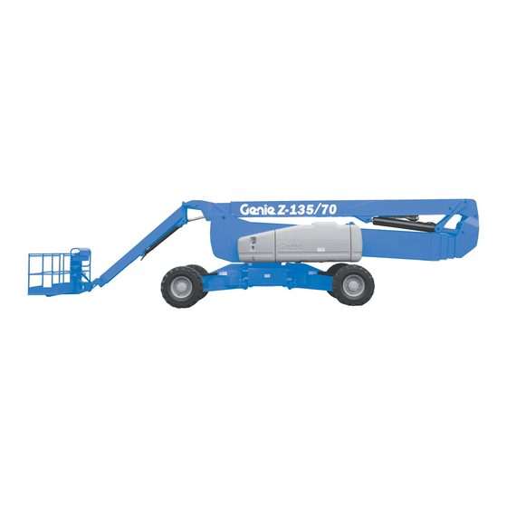
Genie Z-135/70 Manuals
Manuals and User Guides for Genie Z-135/70. We have
7
Genie Z-135/70 manuals available for free PDF download: Service And Repair Manual, Maintenance Manual, Operator's Manual, Installation Instructions Manual
Genie Z-135/70 Service And Repair Manual (253 pages)
Brand:
Genie
| Category:
Boom Lifts
| Size: 8.14 MB
Table of Contents
October
2
Find a Manual for this Model
2
Serial Number Legend
4
Safety Rules
5
Table of Contents
7
Specifications
13
Machine Specifications
13
Performance Specifications
13
Hydraulic Oil Specifications
14
Hydraulic Component Specifications
17
Deutz TD 2.9 Engine Specifications
19
Deutz Td2011L04I Engine Specifications
20
Perkins 854F-34T Engine Specifications
22
Perkins 1104D-44T Engine Specifications
24
Machine Torque Specifications
26
Hydraulic Hose and Fitting Torque Specifications
27
Torque Procedure
28
Repair Procedures
31
Introduction
31
About this Section
32
Platform Controls
33
Platform Circuit Board
34
How to Remove the LED Circuit Board
35
Joysticks - How to Calibrate a Joystick
35
How to Reset a Proportional Valve Coil Default
39
How to Set the Function Thresholds and Default Functions Speeds
40
How to Adjust the Function Speeds
42
How to Adjust the Function Ramp Rate Setting
43
Press the Enter Button to Save the Setting in Memory
43
Press the Enter or Previous Button on the LCD Screen until EXIT Is Displayed
43
Press the Plus Button or Minus Button to
43
Select YES and then Press the Enter Button
43
Platform Components
44
Platform
44
Platform Leveling Cylinder
45
Specifications
45
October
45
Platform Rotator
46
How to Bleed the Platform Rotator
47
Platform Level Sensor - How to Calibrate the Platform Level Sensor
48
Platform Overload System (if Equipped)
49
Platform Overload Recovery Message
51
Jib Boom Components
52
Jib Boom Cable Track
53
How to Repair the Cable Track
55
Jib Boom
56
Note: Perform this Procedure with the Boom in the
56
Stowed Position
56
Jib Boom Lift Cylinder
58
Jib Boom Level Cylinder
59
Jib Boom Extension Cylinder
60
Angle Sensor
62
Note: Use the Following Chart to Identify the Description of each LCD Screen Control Button Used in this Procedure
63
Boom Components
68
Primary Boom Cable Track
69
How to Repair the Primary Boom Cable Track
71
Secondary Boom Cable Track
72
How to Repair the Secondary Boom Cable Track
74
Primary Boom
75
Primary Boom Lift Cylinder
77
Secondary Boom Lift Cylinder
78
Primary Boom Extension Cylinder
82
Secondary Boom Extension Cylinders
83
Sensor
85
Secondary Boom Angle Sensor - How to Calibrate the Secondary Boom Angle Sensor
90
Engines
96
RPM Adjustment
96
Flex Plate
96
How to Install the Flex Plate
97
Ground Controls
98
Bypass/Recovery Key Switch
98
How to Use the Recovery Mode
100
Circuit Boards
101
Membrane Decal
103
Full Machine Calibration
104
Display Module
105
Hydraulic Pumps
114
Function Pump
114
How to Prime the Function Pump
115
How to Adjust the Function Pump Standby Pressure
115
How to Adjust the Function Pump Pressure Compensator
116
Drive Pump
117
How to Prime the Drive Pump
118
Manifolds
120
Function Manifold Components
120
Valve Adjustments - Function Manifold
124
Platform Manifold
126
Jib Boom Manifold
128
Flow Control Mainfold
130
Function Enable Valve
131
Turntable Rotation Manifold
132
Steer and Axle Manifold
134
Valve Adjustments - Steer and Axle Manifold
138
Traction Manifold Components
140
Valve Adjustments - Traction Manifold
144
Drive Oil Diverter Manifold Components (Welder Option)
145
Valve Coils
146
Turntable Rotation Components
148
Turntable Rotation Assembly
148
How to Adjust the Turntable Rotation Gear Backlash
149
Turntable Level Sensor - How to Calibrate the Turntable Level Sensor
150
Axle Components
153
Steer Sensors
153
How to Calibrate a Replacement Steer Sensor
155
How to Calibrate All Steer Sensors
156
October
156
Steer Cylinders
158
Axle Extension Cylinders
159
Axle Angle Sensors - How to Calibrate the Axle Angle Sensors
160
Fault Codes
163
Introduction
163
Section 4 Fault Codes
163
Control System Fault Codes
164
Fault Matrix
181
Deutz TD 2.9 L4 Engine Fault Codes
182
Perkins 854F-34T Engine Fault Code
197
Schematics
205
Introduction
205
Section 5 Schematics
205
Wire Circuit Legend
206
Wire Color Legend
210
Limit Switches and Angle Sensors
215
Circuit Connector Legend
219
Drive Chassis and Platform Controller Pin Legend
222
Safety Controller Pin Legend
223
Turntable Controller Pin Legend
224
Telematics Connector Pin Legend
225
Engine Relay and Fuse Panel Legend - Deutz Td2011L04I
226
Engine Relay and Fuse Panel Legend - Deutz TD2.9
227
Engine Relay and Fuse Panel Legend - Perkins 1104D-44T
228
Engine Relay and Fuse Panel Legend - Perkins 854F-34T
229
Electrical Symbols Legend
230
Hydraulic Symbols Legend
231
Perkins 1104D Engine Electrical Schematic
234
Perkins 854F-34T Engine Electrical Schematic
236
Perkins 854F-34T Engine Harness
237
Deutz TD2.9 Engine Electrical Schematic
240
Deutz TD2.9 Engine Harness
241
Hydraulic Generator (Welder Option)
244
Generator Wiring Schematic
245
Hydraulic Schematic (to SN ZX13516H-2804)
248
Hydraulic Schematic (from SN ZX13516H-2805)
249
Electrical Schematic
251
Electrical Schematic
252
Advertisement
Genie Z-135/70 Maintenance Manual (182 pages)
Brand:
Genie
| Category:
Boom Lifts
| Size: 8.52 MB
Table of Contents
Table of Contents
9
Models Included in this Manual
3
Introduction
3
Identifying the Correct Procedure for Your Model
4
Find Additional Manuals for Your Model
4
Revision History
5
Safety Rules
7
Table of Contents
9
Performance Specifications
15
Function Speeds - S-100, S-105 and S-100HD
15
Function Speeds - S-120, S-125 and S-120HD
16
Function Speeds - All Other Models
17
Maintenance Manual October 2018 Performance Specifications
18
Jib Boom down
19
Jib Boom Rotate
19
Jib Boom up
19
Primary Boom Extend
19
Primary Boom Retract
19
Secondary Boom down
19
Secondary Boom up
19
Turntable Rotate
20
Platform Level (10° Range of Motion)
21
Platform Rotate
21
Drive Speeds
23
Ansi/Csa
25
Tires and Wheels
26
Torque Specifications
26
Trax Torque Specifications
27
Engine Operator and Maintenance Manuals
28
Engine Specifications
28
Deutz Engine Models
29
Perkins Engine Models
30
Ford Engine Models
32
Kubota Engine Models
32
GM Engine Models
33
Continental Engine Models
34
Cummins Engine Models
34
Hydraulic Relief Valves
35
Hydraulic Specifications
35
Hydraulic and Drive Hub Fluid Capacities
38
Hydraulic Oil Specifications
40
Hydraulic Hose and Fitting Torque Specifications
43
Torque Procedure
44
Introduction
46
Maintenance Procedures
46
Maintenance Schedule
48
Pre-Delivery Preparation Report
49
Scheduled - Quarterly October 2018 Maintenance Inspection Report - Booms
50
Scheduled Maintenance Inspection Report - Quarterly or Frequent
50
Boom(S) and Platform
51
Drive Chassis
51
Scheduled Maintenance Inspection Report - Annual
51
Turntable Mechanicals and Hydraulics
51
Programmed Maintenance Inspection Report - Booms
52
Commissioning Procedures
53
Perform 50 Hour Service
53
Perform Engine Maintenance - 50 Hours
53
Perform 150 Hour Service
54
Check for Open Bulletins and Owner Registration
55
Quarterly Maintenance Procedures
55
Battery Inspection
56
Inspect the Electrical Wiring
58
Inspect the Electrical Contactor - DC / Bi-Energy Models
59
Check the Exhaust System
60
Inspect the Tires, Wheels and Lug Nut Torque
60
Check the Generator Belts and Pulleys, Bi-Energy Models
61
Check the Oscillate Directional Valve Linkage (if Equipped)
62
Visual Inspection of the Hydraulic Oil
63
Inspect the Hydraulic Filters
64
Check and Adjust the Engine RPM
65
Test the Ground Control Override
70
Test the Alarm Package (if Equipped
71
Test the Alarm Package (if Equipped)
71
Test the Emergency Power System
72
Test the Engine Idle Select - Engine Models
72
Test the Engine Idle Select Operation
72
Test the Fuel Select Operation - Gasoline/Lpg Models
74
Inspect the Calibration Decal - ALC1000 Models
75
Test the Recovery Mode System - ALC-1000 Models
76
Test the Recovery System - ALC-1000 Models
76
Test the Platform Self-Leveling
77
Confirm the Proper Brake Configuration
78
Test the Drive Brakes
78
Test the Drive Speed - Raised or Extended Position
79
Test the Drive Speed - Stowed Position
79
Test the Drive Speed - Raised and Extended Position
80
Test the Drive Speed - Raised and Extended, ALC1000 Models
80
Sx-105Xc, Sx-125Xc, Sx-135Xc
82
Test the Turntable Level Sensor
82
XC, SX-125 XC, SX-135 XC, SX-150 and SX-180
82
Test the Secondary Boom Angle Sensor
84
Test the Secondary Boom Angle Sensor - Z-135/70 and ZX-135/70
84
Test the Primary Boom Angle Sensor - Z-135/70 and
86
Test the Primary Boom Angle Sensor - Z-135/70 and ZX-135/70
86
Test the Primary Boom Angle Sensor
89
XC, SX-125 XC, SX-135 XC, SX-150 and SX-180
89
Test the Safety Envelope Limit Switches
94
Test the Safety Envelope Limit Switches - Z-135/70, ZX-135/70, SX-105
94
Test the Primary Boom Angle Sensor
98
Test the Primary Boom Angle Sensor - Z-80/60
98
Test the Safety Envelope and Circuits
99
Test the Safety Envelope and Circuits - Z-80/60
99
Check the Safety Envelope Limit Switches and Angle Sensor - S-60X, S-80X, and S-60XC to S60XC-45000
101
And S-125
103
Test the Safety Envelope and Circuits
103
Test the Aircraft Protection System (if Equipped)
109
Inspect the Boom Extend/Retract Cables - All Models
111
Test the Operator Protection Alarm (if Equipped
111
Test the Operator Protection Alarm (if Equipped)
111
Test the Recovery Mode System - ALC-600 Models
112
S60Xcm-101, S-65 XC, S-80 Hf, S-85 Hf, S-80 XC, S-85 XC
113
Test the Primary Boom Angle Sensor - S-60 XC from S60XCH-45001 and S60XCM-101, S-65 XC, S-80 HF, S-85 HF, S-80 XC, S-85 XC
115
Test the Primary Boom Angle Sensor - S-60XC from
115
Annual Maintenance Procedures
117
Grease the Turntable Rotation Bearing and Rotate Gear
117
Check the Turntable Rotation Bearing Bolts
118
Inspect for Turntable Bearing Wear
119
Check the Extendable Axle - S-100, S-105, S-120 and S-125
120
Perform Maintenance- Jib Rotate Bearing
121
Test the Bypass/Recovery Key Switch - ALC1000 Models
122
Grease the Platform Overload Mechanism (if Equipped)
124
S-80XC, S-85XC and Z-45XC Models)
125
Test the Platform Overload System - All Models
125
Test the Platform Overload System - ALC1000 Models
127
Test the Platform Load Sense System - S-60 HC
128
Inspect the Boom Extend/Retract Cables - S-60/65 and S-80/85 Models
129
Inspect the Boom Extend/Retract Cables
131
XC and SX-125 XC
131
Inspect the Boom Extend and Retract Cables - SX-135
133
Check the Drive Hub Oil Level and Fastener Torque
137
Test the Dual Capacity and Platform Overload System
139
XC, SX-125 XC and SX-135 XC
139
Test the Dual Capacity and Platform Overload System - S-60 XC from
141
Z-45 XC Models
141
XC, S-85 XC
142
And Z-62 Models
144
P0-1 Check the Track Tension and Fastener Torque, TRAX Models
144
Programmed Maintenance Procedures
144
P0-2 Check the Track Tension and Fastener Torque, TRAX Models
145
S-40 and S-45 Models
145
P0-3 Grease the Extendable Axles - S-100, S-105, S-120 and S-125
147
P0-4 Continental Engine Maintenance - under 1000 Hours
148
P0-5 Cummins Engine Maintenance - under 1000 Hours
149
P0-6 Deutz Engine Maintenance - under 1000 Hours
150
P0-7 Ford Engine Maintenance - under 1000 Hours
151
P0-8 Kubota Engine Maintenance - under 1000 Hours
152
P0-9 Perkins Engine Maintenance - under 1000 Hours
153
P0-10 GM .998L Engine Maintenance - under 1000 Hours
154
P0-11 GM 3.0L Engine Maintenance - under 1000 Hours
155
P1-1 Perform Engine Maintenance - 1000 Hours
156
P1-2 Replace the Drive Hub Oil
157
P2-1 Perform Engine Maintenance - 2000 Hours
160
P2-2 Test or Replace the Hydraulic Oil
162
P2-3 Replace the Hydraulic Filters
163
P2-4 Check the Free-Wheel Configuration
165
P2-5 Check the Boom Wear Pads
167
P2-6 Check the Extendable Axle Wear Pads - S-100, S-105, S-120, S-125, S-100HD and S-120HD
170
P2-7 Check the Turntable Rotation Gear Backlash
170
P2-8 Grease the Steer Axle Wheel Bearings, All 2WD Models, Except S-60, S-65, Z-60 DC/FE and Z-62
171
DC/FE and Z-62
173
P3-1 Perform Engine Maintenance - 3000 Hours
174
P4-1 Perform Engine Maintenance - 4000 Hours
175
P5-1 Perform Engine Maintenance - 5000 Hours
176
P6-1 Perform Engine Maintenance - 6000 Hours
176
P12-1 Perform Engine Maintenance - 12000 Hours
177
P12-2 Remove and Inspect the Boom Extend/Retract Cables
177
Cable Replacement Criteria
180
Genie Z-135/70 Maintenance Manual (157 pages)
Brand:
Genie
| Category:
Boom Lifts
| Size: 5.94 MB
Table of Contents
Introduction
3
Introduction
2
Models Included in this Manual
3
Identifying the Correct Procedure for Your Model
3
Find Additional Manuals for Your Model
3
Revision History
4
Safety Rules
6
Personal Safety
7
Table of Contents
8
April
12
Performance Specifications
13
Function Speeds - S-100, S-105 and S-100HD
13
April
13
Function Speeds - S-120, S-125 and S-120HD
14
Function Speeds - All Other Models
15
Drive Speeds
19
Torque Specifications
21
Tires and Wheels
21
TRAX Torque Specifications
22
Engine Specifications
23
Engine Operator and Maintenance Manuals
23
Deutz Engine Models
24
Perkins Engine Models
25
Ford Engine Models
26
Kubota Engine Models
27
GM Engine Models
28
Continental Engine Models
28
Cummins Engine Models
29
Hydraulic Specifications
30
Hydraulic Relief Valves
30
Hydraulic and Drive Hub Fluid Capacities
33
Hydraulic Oil Specifications
35
Hydraulic Hose and Fitting Torque Specifications
38
Torque Procedure
39
Maintenance Procedures
41
Introduction
41
About this Section
42
Maintenance Schedule
43
Maintenance Inspection Report
43
Pre-Delivery Preparation Report
44
Scheduled
45
Scheduled Maintenance Inspection Report - Booms
45
Programmed Maintenance Inspection Report - Booms
46
Commissioning Procedures
47
Perform 50 Hour Service
47
Perform Engine Maintenance - 50 Hours
47
Perform 150 Hour Service
48
Quarterly Maintenance Procedures
49
Check for Open Bulletins and Owner Registration
49
Battery Inspection
50
Inspect the Electrical Wiring
52
Inspect the Electrical Contactor - DC / Bi-Energy Models
53
Check the Exhaust System
54
Inspect the Tires, Wheels and Lug Nut Torque
54
Check the Generator Belts and Pulleys, Bi-Energy Models
55
Check the Oscillate Directional Valve Linkage (if Equipped)
56
Visual Inspection of the Hydraulic Oil
57
Inspect the Hydraulic Filters
58
Check and Adjust the Engine RPM
59
Test the Ground Control Override
64
Test the Alarm Package (if Equipped)
64
Test the Emergency Power System
65
Test the Engine Idle Select - Engine Models
66
Test the Fuel Select Operation - Gasoline/Lpg Models
67
Inspect the Calibration Decal - ALC1000 Models
68
Test the Recovery Mode System - ALC-1000 Models
69
Test the Platform Self-Leveling
71
Confirm the Proper Brake Configuration
71
Test the Drive Brakes
72
Test the Drive Speed - Stowed Position
72
Test the Drive Speed - Raised or Extended Position
73
Test the Drive Speed - Raised and Extended, ALC1000 Models
74
Test the Drive Speed - Raised and Extended
74
Test the Turntable Level Sensor
75
Test the Turntable Level Sensor - Z-135/70, ZX135/70, SX-150 and
75
Z-135/70, ZX135/70, SX-150 and SX-180
75
Test the Secondary Boom Angle Sensor - Z-135/70 and ZX135/70
77
Test the Primary Boom Angle Sensor - Z-135/70 and ZX135/70
79
Test the Primary Boom Angle Sensor
79
Test the Primary Boom Angle Sensor - SX-150 and SX-180
82
Test the Primary Boom Angle Sensor
82
Test the Safety Envelope Limit Switches
84
Z-135/70, ZX135/70, SX-150 and SX-180 Models
86
Z-135/70, ZX135/70, SX-150 and
87
Test the Primary Boom Angle Sensor - Z-80/60
88
Test the Primary Boom Angle Sensor
88
Test the Safety Envelope and Circuits - Z-80/60
89
Test the Safety Envelope and Circuits
89
Check the Safety Envelope Limit Switches and Angle Sensor - S-60X, S-60XC and S-80X
91
Check the Safety Envelope Limit Switches and Angle Sensor - S-60X, S-60XC and
91
Test the Safety Envelope and Circuits
93
And S-125
93
Test the Aircraft Protection System (if Equipped)
99
Test the Aircraft Protection System (if Equipped
99
Test the Operator Protection Alarm (if Equipped)
101
Test the Operator Protection Alarm (if Equipped
101
Annual Maintenance Procedures
102
Grease the Turntable Rotation Bearing and Rotate Gear
102
Check the Turntable Rotation Bearing Bolts
103
Inspect for Turntable Bearing Wear
104
Check the Extendable Axle - S-100, S-105, S-120 and S-125
105
Perform Maintenance- Jib Rotate Bearing
106
Test the Bypass/Recovery Key Switch - ALC1000 Models
107
Grease the Platform Overload Mechanism (if Equipped)
110
Test the Platform Overload System - All Models, Except ALC1000 and S-60HC Models
110
Z-30/20N (Rj
110
Test the Platform Overload System - ALC1000 Models
112
Test the Platform Load Sense System - S-60 HC
114
Inspect the Boom Extend/Retract Cables - S-60 and S-80 Models
115
Inspect the Boom Extend/Retract Cables
116
And S-125 Models
116
Inspect the Boom Extend and Retract Cables
118
And SX-180 Models
118
Check the Drive Hub Oil Level and Fastener Torque
119
Programmed Maintenance Procedures
122
S-60, S-65 and Z-62 Models
122
S-40 and S-45 Models
123
P0-3 Grease the Extendable Axles - S-100, S-105, S-120 and S-125
125
P0-4 Continental Engine Maintenance - under 1000 Hours
126
P0-5 Cummins Engine Maintenance - under 1000 Hours
127
P0-6 Deutz Engine Maintenance - under 1000 Hours
128
P0-7 Ford Engine Maintenance - under 1000 Hours
129
P0-8 Kubota Engine Maintenance - under 1000 Hours
130
P0-9 Perkins Engine Maintenance - under 1000 Hours
131
P0-10 GM .998L Engine Maintenance - under 1000 Hours
132
P0-11 GM 3.0L Engine Maintenance - under 1000 Hours
133
P1-1 Perform Engine Maintenance - 1000 Hours
134
P1-2 Replace the Drive Hub Oil
135
P2-1 Perform Engine Maintenance - 2000 Hours
138
P2-2 Test or Replace the Hydraulic Oil
140
P2-3 Replace the Hydraulic Filters
141
P2-4 Check the Free-Wheel Configuration
143
P2-5 Check the Boom Wear Pads
145
Z-30/20N (Rj
146
Z-51/30J
147
P2-6 Check the Extendable Axle Wear Pads - S-100, S-105, S-120, S-125, S-100HD and S-120HD
148
P2-7 Check the Turntable Rotation Gear Backlash
148
P2-8 Grease the Steer Axle Wheel Bearings, All 2WD Models (Except S-60 / S-65, Z-60 DC/FE and Z-62)
149
Z-34/22 be
150
P2-9 Grease the Steer Axle Wheel Bearings, 2WD Models - S-60 /
151
P3-1 Perform Engine Maintenance - 3000 Hours
152
P4-1 Perform Engine Maintenance - 4000 Hours
153
P5-1 Perform Engine Maintenance - 5000 Hours
154
P6-1 Perform Engine Maintenance - 6000 Hours
154
P12-1 Perform Engine Maintenance - 12000 Hours
155
P12-2 Replace the Boom Extend/Retract Cables - S-100HD and S-120HD
155
P12-3 Replace the Boom Extend/Retract Cables - S-60 Models, S-80 Models, S-100, S-105, S-120, S-125, SX-150
156
Advertisement
Genie Z-135/70 Maintenance Manual (178 pages)
Brand:
Genie
| Category:
Boom Lifts
| Size: 8.21 MB
Table of Contents
Table of Contents
9
Maintenance Procedures
42
Introduction
42
Maintenance Schedule
44
Pre-Delivery Preparation Report
45
Scheduled - Quarterly April 2018 Maintenance Inspection Report - Booms
46
Scheduled Maintenance Inspection Report - Quarterly or Frequent
46
Scheduled Maintenance Inspection Report - Annual
47
Programmed Maintenance Inspection Report - Booms
48
Commissioning Procedures
49
Perform 50 Hour Service
49
Perform Engine Maintenance - 50 Hours
49
Perform 150 Hour Service
50
Check for Open Bulletins and Owner Registration
51
Quarterly Maintenance Procedures
51
Battery Inspection
52
Inspect the Electrical Wiring
54
Inspect the Electrical Contactor - DC / Bi-Energy Models
55
Check the Exhaust System
56
Inspect the Tires, Wheels and Lug Nut Torque
56
Check the Generator Belts and Pulleys, Bi-Energy Models
57
Check the Oscillate Directional Valve Linkage (if Equipped)
58
Visual Inspection of the Hydraulic Oil
59
Inspect the Hydraulic Filters
60
Check and Adjust the Engine RPM
61
Test the Ground Control Override
66
Test the Alarm Package (if Equipped
67
Test the Alarm Package (if Equipped)
67
Test the Emergency Power System
68
Test the Engine Idle Select - Engine Models
68
Test the Engine Idle Select Operation
68
Test the Fuel Select Operation - Gasoline/Lpg Models
70
Inspect the Calibration Decal - ALC1000 Models
71
Test the Recovery Mode System - ALC-1000 Models
72
Test the Recovery System - ALC-1000 Models
72
Test the Platform Self-Leveling
73
Confirm the Proper Brake Configuration
74
Test the Drive Brakes
74
Test the Drive Speed - Raised or Extended Position
75
Test the Drive Speed - Stowed Position
75
Test the Drive Speed - Raised and Extended Position
76
Test the Drive Speed - Raised and Extended, ALC1000 Models
76
Test the Turntable Level Sensor
78
XC, SX-125 XC, SX-135 XC, SX-150 and SX-180
78
Test the Secondary Boom Angle Sensor - Z-135/70 and ZX-135/70
80
Test the Turntable Level Sensor
81
Test the Primary Boom Angle Sensor - Z-135/70 and ZX-135/70
82
Test the Secondary Boom Angle Sensor
82
Test the Primary Boom Angle Sensor
85
XC, SX-125 XC, SX-135 XC, SX-150 and SX-180
85
Test the Safety Envelope Limit Switches
90
XC, SX-125 XC, SX-135 XC, SX-150 and SX-180
90
Test the Primary Boom Angle Sensor
94
Test the Primary Boom Angle Sensor - Z-80/60
94
Test the Safety Envelope and Circuits
95
Test the Safety Envelope and Circuits - Z-80/60
95
Check the Safety Envelope Limit Switches and Angle
97
Check the Safety Envelope Limit Switches and Angle Sensor - S-60X, S-60XC and S-80X
97
And S-125
99
Test the Safety Envelope and Circuits
99
Test the Aircraft Protection System (if Equipped
105
Test the Aircraft Protection System (if Equipped)
105
Inspect the Boom Extend/Retract Cables - All Models
107
Test the Operator Protection Alarm (if Equipped)
107
Test the Recovery Mode System - ALC-600 Models
108
Test the Turntable Level Sensor - S-80 XC and S-85 XC
109
Test the Primary Boom Angle Sensor - S-80 XC, S-85 XC
111
Annual Maintenance Procedures
113
Grease the Turntable Rotation Bearing and Rotate Gear
113
Check the Turntable Rotation Bearing Bolts
114
Inspect for Turntable Bearing Wear
115
Check the Extendable Axle - S-100, S-105, S-120 and S-125
116
Perform Maintenance- Jib Rotate Bearing
117
Test the Bypass/Recovery Key Switch - ALC1000 Models
118
Grease the Platform Overload Mechanism (if Equipped)
120
All Models, Except ALC1000 and S-60HC Models
121
Test the Platform Overload System
121
Test the Platform Overload System - ALC1000 Models
123
Test the Platform Load Sense System - S-60 HC
124
Inspect the Boom Extend/Retract Cables - S-60 and S-80 Models
125
Inspect the Boom Extend/Retract Cables - S-100, S-105, S-120, S-125, SX-105 XC and SX-125 XC
127
Inspect the Boom Extend and Retract Cables
129
XC, SX-150 and SX-180
129
Check the Drive Hub Oil Level and Fastener Torque
133
Test the Dual Capacity and Platform Overload System
135
Test the Dual Capacity and Platform Overload System - S-80 XC and SX-85 XC
135
XC, SX-125 XC and SX-135 XC
135
Z-45 XC Models
137
P0-1 Check the Track Tension and Fastener Torque, TRAX Models
140
Programmed Maintenance Procedures
140
S-60, S-65 and Z-62 Models
140
P0-2 Check the Track Tension and Fastener Torque, TRAX Models
141
S-40 and S-45 Models
141
P0-3 Grease the Extendable Axles - S-100, S-105, S-120 and S-125
143
P0-4 Continental Engine Maintenance - under 1000 Hours
144
P0-5 Cummins Engine Maintenance - under 1000 Hours
145
P0-6 Deutz Engine Maintenance - under 1000 Hours
146
P0-7 Ford Engine Maintenance - under 1000 Hours
147
P0-8 Kubota Engine Maintenance - under 1000 Hours
148
P0-9 Perkins Engine Maintenance - under 1000 Hours
149
P0-10 GM .998L Engine Maintenance - under 1000 Hours
150
P0-11 GM 3.0L Engine Maintenance - under 1000 Hours
151
P1-1 Perform Engine Maintenance - 1000 Hours
152
P1-2 Replace the Drive Hub Oil
153
P2-1 Perform Engine Maintenance - 2000 Hours
156
P2-2 Test or Replace the Hydraulic Oil
158
P2-3 Replace the Hydraulic Filters
159
P2-4 Check the Free-Wheel Configuration
161
P2-5 Check the Boom Wear Pads
163
P2-6 Check the Extendable Axle Wear Pads - S-100, S-105, S-120, S-125, S-100HD and S-120HD
166
P2-7 Check the Turntable Rotation Gear Backlash
166
P2-8 Grease the Steer Axle Wheel Bearings, All 2WD Models, Except S-60, S-65, Z-60 DC/FE and Z-62
167
P2-9 Grease the Steer Axle Wheel Bearings, 2WD Models - S-60, S-65, Z-60 DC/FE and Z-62
169
P3-1 Perform Engine Maintenance - 3000 Hours
170
P4-1 Perform Engine Maintenance - 4000 Hours
171
P5-1 Perform Engine Maintenance - 5000 Hours
172
P6-1 Perform Engine Maintenance - 6000 Hours
172
P12-1 Perform Engine Maintenance - 12000 Hours
173
P12-2 Remove and Inspect the Boom Extend/Retract Cables
173
Cable Replacement Criteria
176
Genie Z-135/70 Operator's Manual (69 pages)
Brand:
Genie
| Category:
Boom Lifts
| Size: 3.42 MB
Table of Contents
Table of Contents
2
Do Not Operate Unless
3
Introduction
3
Hazard Classification
4
Intended Use
4
Safety Sign Maintenance
4
Symbols and Hazard Pictorials Definitions
5
Symbol and Hazard Pictorials Definitions
6
Safety Signs and Locations
7
General Safety
7
Fall Protection
13
Personal Safety
13
Tip-Over Hazards
14
Electrocution Hazards
14
Work Area Safety
14
Operation on Slopes Hazards
17
Fall Hazards
17
Collision Hazards
18
Bodily Injury Hazard
18
Explosion and Fire Hazards
19
Damaged Machine Hazards
19
Component Damage Hazards
19
Battery Safety
19
Pipe Cradle Safety
20
Panel Cradle Safety
20
Lockout after each Use
21
Weld Line to Platform Safety
21
Welder Safety
21
Legend
22
Controls
23
Ground Control Panel
24
Platform Control Panel
28
Pre-Operation Inspection Fundamentals
31
Inspections
31
Pre-Operation Inspection
32
Function Test Fundamentals
33
At the Ground Controls
33
Test Emergency Stop
33
Test the Extendable Axles
33
Test the Tilt Sensor
35
Test the Machine Functions
35
Test Emergency/Auxiliary Controls
35
At the Platform Controls
36
Test the Horn
36
Test the Tilt Sensor Alarm
36
Test the Operating Envelope
36
Test the Foot Switch
37
Test Machine Functions
37
Test the Steering
37
Test Drive and Braking
39
Test the Drive Enable System
39
Test Limited Drive Speed
39
Test Emergency, Auxiliary Controls
40
Test Aircraft Protection Package
40
Workplace Inspection
41
Inspection for Decals with Words
42
Decal Inspection Continued from Preceding Page
44
Inspection for Decals with Symbols
46
Operating Instructions
48
Starting the Engine
49
Emergency Stop
49
Emergency/Auxiliary Power
49
To Extend and Retract Axles
50
Operation from Ground
50
To Position Platform
50
Operation from Platform
50
To Steer
51
To Drive
51
Driving on a Slope
52
To Determine the Slope Grade
52
Drive Enable
53
Engine Idle Select
53
Check Engine Light
53
Operating Envelope Indicator Lights
54
Generator
55
Aircraft Protection Package
55
After each Use
55
Platform out of Level (P22 Code)
55
Pipe Cradle Installation
56
Observe and Obey
56
Pipe Cradle Instructions
56
Pipe Cradle Operation
57
Maximum Pipe Cradle Capacity
57
Pipe Cradle Assembly Weight
57
Panel Cradle Assembly
58
Installation of Padding
58
Panel Cradle Installation
58
Installation of Strap
58
Panel Cradle Operation
59
Free-Wheel Configuration for Winching
60
Transport and Lifting Instructions
60
Securing the Platform
61
Securing the Chassis
61
Securing to Truck or Trailer for Transit
61
Lifting Instructions
62
Maintenance Symbols Legend
63
Check the Engine Oil Level
63
Maintenance
63
Check the Hydraulic Oil Level
64
Check the Batteries
64
Hydraulic Oil Specifications
64
Check the Engine Coolant Level - Liquid Cooled Models
65
Scheduled Maintenance
65
Specifications
66
Z-135/70 Range of Motion
67
Genie Z-135/70 Operator's Manual (59 pages)
Brand:
Genie
| Category:
Boom Lifts
| Size: 1.14 MB
Table of Contents
Table of Contents
2
Introduction
3
Symbols and Hazard Pictorials Definitions
5
Symbol and Hazard Pictorials Definitions
6
General Safety
7
Personal Safety
9
Work Area Safety
10
Legend
18
Controls
19
Inspections
27
Workplace Inspection
37
Operating Instructions
40
Emergency Stop
41
Transport and Lifting Instructions
51
Maintenance
54
Specifications
57
Genie Z-135/70 Installation Instructions Manual (16 pages)
Software Update
Brand:
Genie
| Category:
Boom Lifts
| Size: 0.73 MB
Advertisement
Related Products
Genie Z-30
Genie Z45/25J
Genie Z-30HD
Genie Z-30N
Genie Z-20N
Genie Z-51/30J
Genie Z-80/60
Genie Z-45/25 IC
Genie Z-45/25 BE
Genie Z-60/34
Genie Categories
Garage Door Opener
Lifting Systems
Boom Lifts
Security Camera
Digital Camera
More Genie Manuals
Login
Sign In
OR
Sign in with Facebook
Sign in with Google
Upload manual
Upload from disk
Upload from URL