Genie Z-135/70 Operator's Manual
Hide thumbs
Also See for Z-135/70:
- Operator's manual (59 pages) ,
- Installation instructions manual (16 pages) ,
- Service and repair manual (253 pages)
Table of Contents
Advertisement
Advertisement
Table of Contents

Related Manuals for Genie Z-135/70


Summary of Contents for Genie Z-135/70
-
Page 2: Table Of Contents
Only trained and authorized personnel shall be permitted to operate this machine. This manual should be considered a permanent part of your machine and should remain with the machine at all times. If you have any questions, call Genie. Contents Page Introduction ..............1 Symbols and Hazard Pictorials Definitions .... -
Page 3: Introduction
Operator's Manual Introduction Owners, Users and Operators: Genie appreciates your choice of our machine for your application. Our number one priority is user safety, which is best achieved by our joint efforts. We feel that you make a major contribution to... - Page 4 Second Edition · Fourth Printing Introduction Hazard Classification Intended Use Genie uses symbols, color coding and signal words This machine is intended to be used only to lift to identify the following: personnel, along with their tools and materials to an aerial work site.
-
Page 5: Symbols And Hazard Pictorials Definitions
Explosion Hazard or other high energy starting Platform downhill: Platform uphill: aids on machines 1 Retract primary 1 Lower primary equipped with 2 Retract/lower 2 Retract/lower glow plugs. secondary secondary 3 Lower primary 3 Retract primary Part No. 114474 Z-135/70... -
Page 6: Symbol And Hazard Pictorials Definitions
Avoid contact. Tie-down Tie-down Weight of welder Wind speed instructions instructions reduces capacity Fire Hazard Fire extinguisher Accesss by No step. Do not jump-start trained and this battery. authorized personnel only Z-135/70 Part No. 114474... -
Page 7: General Safety
Death or serious injury can starting aids on Disconnect all the batteries before performing service on result from the use of ether or machines equipped this machine. other high energy starting with glow plugs. aids. 97602 B 97865 B Part No. 114474 Z-135/70... - Page 8 • Read operator's Platform downhill: a severe slope. manual before 1 Retract primary boom. Death or serious attempting to move 2 Retract/lower secondary boom. injury will result. machine. 3 Lower primary boom. 133236 A Z-135/70 Part No. 114474...
- Page 9 28161 C Tire Size 97715 B 445/65 D22.5, 18 ply Foam-filled 97865 82314 1263543 31060 31060 1263543 97875 28161 114389 52865 97715 97715 114390 28177 1263543 28181 or 229356 or 229356 82237 31788 or 230977 or 230977 Part No. 114474 Z-135/70...
- Page 10 Operator's Manual Second Edition · Fourth Printing General Safety Safety signs and locations 133079 82548 114251 133067 1263542 1263542 82472 114249 114249 82472 114251 1263542 114251 A 82472 B 133067 133079 133179 A 114249 82548 114249 A Z-135/70 Part No. 114474...
- Page 11 Second Edition · Fourth Printing Operator's Manual General Safety Safety signs and locations 272 kg < = 272 kg 82546 B Part No. 114474 Z-135/70...
- Page 12 133179 A 82487 1263542 82487 B 133180 133067 82481 82481 B 133180 A 82472 114249 114249 A 82472 B 133079 133180 1263542 114252 114252 114252 82472 82487 82487 1263542 82487 114249 82548 133067 114247 1263542 114249 82481 Z-135/70 Part No. 114474...
-
Page 13: Personal Safety
Operators must comply with employer, job site and governmental rules regarding the use of personal protective equipment. All PFPE must comply with applicable governmental regulations, and must be inspected and used in accordance with the PFPE manufacturer’s instructions. Part No. 114474 Z-135/70... -
Page 14: Work Area Safety
350 to 500KV 25 ft 7.6 m 500 to 750KV 35 ft 10.6 m If using accessories, read, understand and obey the decals, manuals and instructions with the 750 to 1000KV 45 ft 13.7 m accessory. Z-135/70 Part No. 114474... - Page 15 2 Retract/lower the secondary boom. 3 Retract the primary boom. If the tilt alarm sounds with the platform downhill: 1 Retract the primary boom. 2 Retract/lower the secondary boom. 3 Lower the primary boom. Part No. 114474 Z-135/70...
- Page 16 Be sure all tires are in good condition and lug nuts that is caught, snagged or otherwise prevented are properly tightened. from normal motion by an adjacent structure. All personnel must be removed from the platform before attempting to free the platform using the ground controls. Z-135/70 Part No. 114474...
- Page 17 Lower the platform entry mid-rail or close the entry gate before operating. Do not enter or exit the platform unless the machine is in the stowed position and the platform is at ground level. Part No. 114474 Z-135/70...
- Page 18 Do not operate a boom in the path of any crane unless the controls of the crane have been locked out and/or precautions have been taken to prevent any potential collision. Z-135/70 Part No. 114474...
- Page 19 Be sure all maintenance has been performed as specified in this manual and the appropriate Genie Explosion Hazard service manual. Keep sparks, flames Be sure all decals are in place and legible.
- Page 20 Do not cause a horizontal force or side load to the machine by raising or lowering a fixed or Maximum panel area: 32 sq. ft / 3 m overhanging load. Electrocution Hazard: Keep pipes away from all energized electrical conductors. Z-135/70 Part No. 114474...
- Page 21 3 Rotate the turntable so that the boom is between the non-steer wheels. 4 Turn the key switch to the off position and remove the key to secure from unauthorized use. 5 Chock the wheels. Part No. 114474 Z-135/70...
-
Page 22: Legend
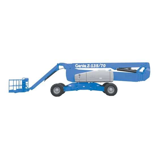
Second Edition · Fourth Printing Legend 1 Square-end tire 8 Sliding mid-rail 2 Ground controls 9 Manual storage container 3 Secondary boom 10 Lanyard anchorage point 4 Primary boom 11 Foot switch 5 Jib boom 6 Platform 7 Platform controls Z-135/70 Part No. 114474... -
Page 23: Controls
The descriptions in this section and the instructions in the Function Test and Operating Instructions sections apply to both panels, unless specifically noted. Bypass Recovery STOP Bypass Recovery Part No. 114474 Z-135/70... - Page 24 Push the jib boom up button and the jib boom to operate at high speed. will raise. Push the jib boom down button and the jib boom will lower. Z-135/70 Part No. 114474...
- Page 25 19 Primary boom up/down buttons Push the primary boom up button and the primary boom will raise. Push the primary boom down button and the primary boom will lower. 20 LCD screen control buttons Part No. 114474 Z-135/70...
- Page 26 Z-135 machines will have one of these two styles of platform control panel. The descriptions in this section and the instructions in the Function Test and Operating Instructions sections apply to both panels, unless specifically noted. Z-135/70 Part No. 114474...
- Page 27 Second Edition · Fourth Printing Operator's Manual Controls Part No. 114474 Z-135/70...
- Page 28 (engine) fails. machine. Move and hold the switch, or push and hold the button. Activate the desired function. The indicator light will be on when emergency/ auxiliary power is being used. Z-135/70 Part No. 114474...
- Page 29 Move the control handle up and the secondary boom will raise and then extend. Move the control handle down and the secondary boom will retract and then lower. Part No. 114474 Z-135/70...
- Page 30 31 Axle retract button with indicator light Push the axle retract button to retract the axles. The indicator light will flash while the axles are retracting and stay on when the axles are fully retracted. Z-135/70 Part No. 114474...
-
Page 31: Inspections
Scheduled maintenance inspections shall be performed by qualified service technicians, according to the manufacturer's specifications and the requirements listed in the responsibilities manual. Part No. 114474 Z-135/70... - Page 32 Hydraulic hoses, fittings, cylinders and manifolds Fuel and hydraulic tanks Drive and turntable motors and drive hubs Boom wear pads Tires and wheels Engine and related components Limit switches and horn Rotation sensors Z-135/70 Part No. 114474...
- Page 33 After repairs are completed, the operator must perform a pre-operation inspection and function tests again before putting the machine into service. Part No. 114474 Z-135/70...
- Page 34 Result: The primary boom should extend and retract normally. 18 Push and hold a function enable/speed select button and push the turntable rotate left button and then the turntable rotate right button. Result: The turntable should rotate normally. Z-135/70 Part No. 114474...
- Page 35 23 Simultaneously push and hold the emergency/auxiliary power button and push each boom function button. Note: To conserve battery power, test each function through a partial cycle. Result: All boom functions should operate. 24 Start the engine. Part No. 114474 Z-135/70...
- Page 36 The secondary boom should not extend until it is fully raised. 34 Push and hold the secondary boom down/retract button. Result: The secondary boom should fully retract and then lower. The secondary boom should not lower unless it is fully retracted. Z-135/70 Part No. 114474...
- Page 37 OR press the thumb rocker switch in the direction indicated by the yellow triangle. Result: The circle-end wheels should turn in the direction that the blue triangles point on the drive chassis. Part No. 114474 Z-135/70...
- Page 38 Result: All wheels should turn in the direction that the yellow triangles point on the drive chassis. Z-135/70 Part No. 114474...
- Page 39 Note: The machine will travel 40 feet / 12 m in 40 Result: No drive function should operate. seconds. 69 Push the drive enable button or move the drive enable switch, and slowly move the drive/steer control handle off center. Result: The drive function should operate. Part No. 114474 Z-135/70...
- Page 40 If the drive speed with the jib boom extended and the primary boom extended exceeds 6 inches / 15 cm per second, immediately tag and remove the machine from service. 84 Retract the primary boom and the jib boom. Z-135/70 Part No. 114474...
-
Page 41: Workplace Inspection
It should be performed by the operator prior to moving the machine to the workplace. It is the operator's responsibility to read and remember the workplace hazards, then watch for and avoid them while moving, setting up and operating the machine. Part No. 114474 Z-135/70... - Page 42 Warning - Failure To Read . . . 97603 Notice - Engine Specifications, Perkins 31060 Danger - Tip-over Hazard 97705 Cosmetic - Genie Z-135/70 31788 Danger - Battery Safety 97708 Label - Fuse and Relay Panel Layout 32998 Notice - Max. Capacity, 600 lbs / 272 kg...
- Page 43 28174 or 28235 97875 82366 28161 114389 97885 52865 82410 1263543 & serial 97715 or label 97889 97716 72875 229356 or 97715 or 114390 28177 230977 1263543 28181 229356 or 44981 82237 40434 31788 97716 1000257 230977 Part No. 114474 Z-135/70...
- Page 44 230985 Ground Control Panel 97889 Cosmetic - Z-135 233130 Platform Control Panel 97891 Cosmetic - Genie Z-135 1000083 Notice - Start and Controls Battery 102188 Notice - Engine Specifications, Cummins 1000084 Caution - Auxiliary Batteries 114258 Label - No Smoking...
- Page 45 28174 or 28235 97875 82366 28161 114389 97885 52865 82410 1263543 & serial 97715 or label 97889 97716 72875 229356 or 97715 or 114390 28177 230977 1263543 28181 229356 or 44981 82237 40434 31788 97716 1000257 230977 Part No. 114474 Z-135/70...
- Page 46 Part No. Description Quantity 27204 Arrow - Blue 82841 Platform Control Panel 27205 Arrow - Yellow 97705 Cosmetic - Genie Z-135/70 27206 Triangle - Blue 97716 Label - Wheel Load 27207 Triangle - Yellow 97757 Label - Hydraulic Oil Level...
- Page 47 1263545 97757 133079 1263542 133180 1263556 114252 or 230985 114252 1263544 97891 114252 28174 or 28235 82472 1263542 82487 82487 82487 133067 114249 82548 1263542 97889 97716 114247 serial 44981 40434 82481 97716 label 1000257 114249 Part No. 114474 Z-135/70...
-
Page 48: Operating Instructions
That means 4 Inspect the workplace. every new operator should perform a pre-operation inspection, function tests, and a workplace 5 Only use the machine as it was intended. inspection before using the machine. Z-135/70 Part No. 114474... -
Page 49: Emergency Stop
Attempting to start the engine when desired function. The indicator light will be on when emergency power temperatures are below 0°F / -18°C may require the is being used. use of a booster battery. Part No. 114474 Z-135/70... - Page 50 1 Press down the foot switch. the on position. 2 Slowly move the appropriate function control 3 Start the engine. handle or toggle switch or press the appropriate button according to the markings on the control panel. Z-135/70 Part No. 114474...
- Page 51 Use the color-coded direction arrows on the platform controls and the drive chassis to identify the direction the wheels will turn. Part No. 114474 Z-135/70...
- Page 52 0.3 m 3.6 m = 0.083 x 100 = 8.3% grade If the slope exceeds the maximum uphill, downhill or side slope rating, then the machine must be winched or transported up or down the slope. See the Transport and Lifting section. Z-135/70 Part No. 114474...
- Page 53 Light on and engine still running: the direction the machine will travel. Contact service personnel within 24 hours. When the drive enable light is on, the axles cannot retract. Part No. 114474 Z-135/70...
- Page 54 Move the machine to a light is flashing. The Platform firm, level surface. Level toggle switch will only work in the direction that will level the platform. Level the platform until the indicator light is off. Z-135/70 Part No. 114474...
- Page 55 3 Rotate the turntable so that the boom is between the circle-end wheels. 4 Turn the key switch to the off position and remove the key to secure from unauthorized use. 5 Chock the wheels. Part No. 114474 Z-135/70...
- Page 56 3 Secure each U-bolt with 2 washers and 2 nuts. a strap e pipe cradle weldment b U-bolts middle platform c pipe cradle mount railing d upper platform g flat washers railing -inch nylock nuts Z-135/70 Part No. 114474...
- Page 57 Maximum Pipe Cradle Capacity All models 200 lbs 90.7 kg Pipe Cradle Assembly Weight 21 lbs 9.5 kg Part No. 114474 Z-135/70...
- Page 58 8 Place the tube between the panel cradle and the platform floor. Insert the U-bolt through the floor, around the tube and into the panel cradle base. 9 Repeat above for the second set of parts. Z-135/70 Part No. 114474...
- Page 59 U-bolt mounting 3 Center the load on the platform. rubber slots bumper 1 4 Secure the load to the platform using the strap. Tighten the strap. panel decal cradle base hook piece padding clamp hook Part No. 114474 Z-135/70...
-
Page 60: Transport And Lifting Instructions
Observe and Obey: section. If the slope of the transport vehicle bed exceeds Genie provides this securement information as a the uphill or downhill maximum slope rating, the recommendation. Drivers are solely responsible machine must be loaded and unloaded using a for making sure machines are properly secured winch as described. - Page 61 41 cm 12.97 m 10 ft 3.07 m 4 ft 4 in 1.31 m 10 ft 10 in 19 ft 2 in 14 ft 3.3 m 5.84 m 4.25 m 25 ft 1 in 7.65 m Part No. 114474 Z-135/70...
- Page 62 Adjust the rigging to prevent damage to the and straps or lines are sufficient to withstand machine and to keep the machine level. the machine weight. See the serial label for the machine weight. 59.5 in 1.5 m 56 in 1.4 m Z-135/70 Part No. 114474...
-
Page 63: Maintenance
Oil type 15W-40 responsibilities manual. Oil type - cold conditions, 1104C 10W-30 Use only Genie approved replacement parts. Oil type - cold conditions, 804D 5W-40 Deutz BF4L2011 and TD2011L04i Engine Oil type 15W-40 Maintenance Symbols Legend... - Page 64 Do not overfill. Hydraulic oil specifications 6 Install the vent caps. Hydraulic oil type Chevron Rykon® Note: Adding terminal protectors and a corrosion Premium MV equivalent preventative sealant will help eliminate corrosion on the battery terminals and cables. Z-135/70 Part No. 114474...
- Page 65 Machines that have been out of service for more than three months must receive the quarterly inspection before they are put back into service. Part No. 114474 Z-135/70...
-
Page 66: Specifications
(length x width) 1.8 m x 76 cm Platform dimensions, 8 foot 96 in x 36 in Continuous improvement of our products is a Genie (length x width) 2.4 m x 91 cm policy. Product specifications are subject to change without notice or obligation. - Page 67 Second Edition · Fourth Printing Operator's Manual Specifications Z-135/70 Range of Motion Part No. 114474 Z-135/70...