Sign In
Upload
Manuals
Brands
Fisher Manuals
Controller
FIELDVUE DVC6200
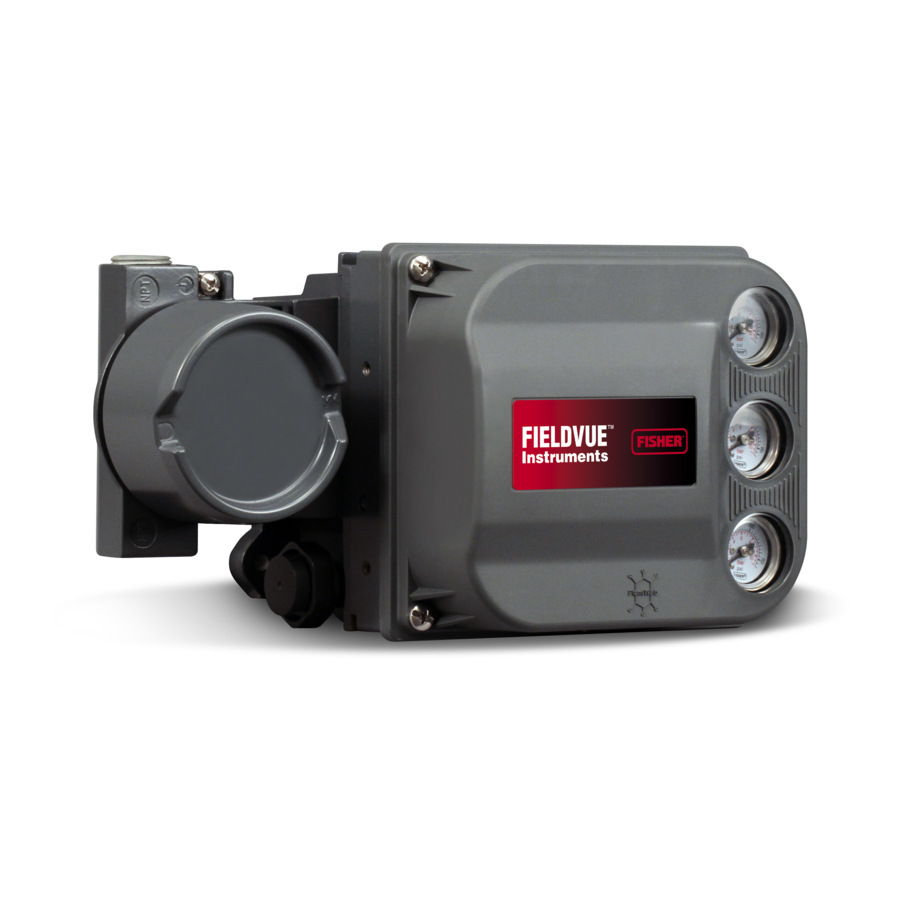
Fisher FIELDVUE DVC6200 Manuals
Manuals and User Guides for Fisher FIELDVUE DVC6200. We have
11
Fisher FIELDVUE DVC6200 manuals available for free PDF download: Instruction Manual, Quick Start Manual, Mounting Instructions, Instruction Manual Supplement
Fisher FIELDVUE DVC6200 Instruction Manual (148 pages)
Digital Valve Controller
Brand:
Fisher
| Category:
Controller
| Size: 3.34 MB
Table of Contents
™ Fisherr Fieldvuedvc6200 Digital Valve Controller
1
Table of Contents
1
Contents
2
Section 1 Introduction
3
Scope of Manual
3
Conventions Used in this Manual
3
Device Revision 2
3
Description
4
Specifications
5
Related Documents
8
Educational Services
9
Section 2 Installation
11
Mounting the DVC6200
11
Mounting the DVC6205 Base Unit
14
Mounting the DVC6215 Feedback Unit
16
Sliding-Stem Linear Actuators up to 210 MM (8 Inches) of Travel
18
Fisher Rotary Actuators and Sliding-Stem Linear Actuators
20
GX Actuators
22
Quarter-Turn Rotary Actuators
25
Mounting Fisher 67CFR Filter Regulator
26
Pneumatic Connections
26
Pressure
26
Supply
27
Output Connection
28
Special Construction to Support Solenoid Valve Testing
29
Vent
30
Wiring and Electrical Connections
30
4-20 Ma Loop Connections
31
Remote Travel Sensor Connections
32
Wiring Practices
34
Control System Requirements
34
HART Filter
34
Voltage Available
35
Compliance Voltage
37
Maximum Cable Capacitance
37
Installation in Conjunction with a Rosemountt 333 HART Tri-Loopt HART-To-Analog Signal Converter
38
Section 3 Basic Setup
41
Instrument Mode
41
Configuration Protection
41
Basic Setup
42
Setup Wizard
42
Performance Tuner
44
Stabilizing/Optimizing Valve Response
45
Section 4 Detailed Setup
47
Mode and Protection
49
Mode
49
Protection
50
Detailed Setup
51
Protection and Response Control
52
Travel Tuning
52
Tuning
52
Integral Settings
55
Pressure Tuning
55
Travel/Pressure Control
56
Define Custom Characterization
58
Input Characterization
58
Dynamic Response
59
Alerts
60
Electronics Alerts
61
Processor Impaired Alerts
61
Sensor Alerts
62
Environmental Alerts
62
Travel Alerts
63
Travel History Alerts
65
SIS Alerts
66
Alert Record
67
Status
68
Instrument
69
Valve & Actuator
71
Partial Stroke
73
Section 5 Calibration
77
Calibration Overview
77
Calibrate
77
Travel Calibration
78
Auto Calibration
78
Manual Calibration
79
Sensor Calibration
80
Pressure Sensor Calibration
80
Analog Input Calibration
82
Relay Adjustment
83
Double-Acting Relay
83
Single-Acting Relays
85
Restore Factory Settings
85
Section 6 Viewing Device Variables and Diagnostics
87
Service Tools
87
Overview
93
Section 7 Maintenance and Troubleshooting
97
Replacing the Magnetic Feedback Assembly
98
Module Base Maintenance
98
Tools Required
98
Component Replacement
99
Removing the Module Base
99
Replacing the Module Base
100
Submodule Maintenance
101
I/P Converter
101
Printed Wiring Board (PWB) Assembly
103
Pneumatic Relay
105
Gauges, Pipe Plugs or Tire Valves
105
Terminal Box
106
Removing the Terminal Box
106
Replacing the Terminal Box
107
DVC6215 Feedback Unit
107
Troubleshooting
107
Checking Voltage Available
107
Checking Loop Current
108
Section 8 Parts
113
Parts Ordering
113
Parts Kits
113
Parts List
114
Housing
114
Common Parts
114
Module Base
114
I/P Converter Assembly
115
Relay
115
Terminal Box
115
Feedback Connection Terminal Box
115
PWB Assembly
116
Pressure Gauges, Pipe Plugs, or Tire Valve Assemblies
116
HART Filters
116
Appendix A Principle of Operation
123
HART Communication
123
DVC6200 Digital Valve Controller
123
Appendix B Field Communicator Menu Tree
127
Burst Mode Enable
128
Control Mode N N N N
128
HART Tag
128
Date
130
Descriptor
130
Message
130
Actuator Style
133
Analog in Units
133
Input Range High
133
Input Range Low
133
Inst Serial Num
133
Polling Address
133
Pressure Units
133
Relay Type
133
Valve Serial Num
133
Valve Style
133
Glossary
135
Set Point Filter Time (Lag Time)
139
Index
143
Advertisement
Fisher FIELDVUE DVC6200 Instruction Manual (116 pages)
Digital Valve Controller
Brand:
Fisher
| Category:
Controller
| Size: 1.85 MB
Table of Contents
Introduction and Specifications Section 1 Introduction 1
9
Table of Contents
9
Section 1 Introduction
9
Scope of Manual
10
Conventions Used in this Manual
10
Device Revision
10
Description
11
Specifications
11
Related Documents
11
Educational Services
12
Device Type
15
Installation
17
Section 2 Installation
18
Special Instructions for "Safe Use" and Installations
18
Csa
18
Iecex
19
Mounting the DVC6200
19
Mounting Fisher 67CFR Filter Regulator
22
Pneumatic Connections
23
Pressure
23
Supply
23
Output Connection
24
Special Construction to Support Solenoid Valve Testing
24
Vent
24
Wiring and Electrical Connections
26
4−20 Ma Loop Connections
26
Wiring Practices
27
Control System Requirements
27
HART Filter
27
Voltage Available
28
Compliance Voltage
29
Maximum Cable Capacitance
30
Installation in Conjunction with a Rosemountt 333 HART Tri-Loop
30
HART-To-Analog Signal Converter
30
Basic Setup
33
Configuration Protection
34
Basic Setup
34
Calibration
34
Setup Wizard
35
Performance Tuner
36
Stabilizing/Optimizing Valve Response
36
Instrument Mode
34
Detailed Setup
37
Parts
39
Menu and Quick Key Sequence Tables
40
Detailed Setup
40
Mode and Protection
40
Burst Mode
41
Control Mode
41
Restart Control Mode
41
Protection
42
Response Control
42
Travel Tuning
42
Tuning
42
Performance Tuner
44
Stabilize/Optimize
44
Integral Settings
45
Pressure Tuning
45
Cycle Count/Travel Accumulator Deadband Travel Accumulator SIS Alerts
53
Travel History Alerts
53
Alert Groups
54
Alert Record
54
Pressure Deviation Time
54
Instrument
55
Integrator
55
Status
55
Analog Input Range
56
Relay Type
57
Valve & Actuator
57
Partial Stroke
58
PST Enable
58
Calibration
61
Calibration Overview
62
Section 5 Calibration
62
Calibrate
62
Travel Calibration
62
Auto Calibration
62
Analog Calibration Adjust
63
Manual Calibration
63
Digital Calibration Adjust
64
Sensor Calibration
64
Pressure Sensor Calibration
64
Supply Pressure Sensor Calibration
65
Analog Input Calibration
66
Relay Adjustment
66
Double-Acting Relay
66
Single-Acting Relays
67
Restore Factory Settings
67
Viewing Device Variables and Diagnostics
69
Viewing Device Variables and Diagnostics
71
Viewing Device Variables and Diagnostics
73
Viewing Device Variables and Diagnostics
75
Maintenance and Troubleshooting
77
Section 7 Maintenance and Troubleshooting
79
Module Base Maintenance
79
Tools Required
79
Component Replacement
79
Removing the Module Base
79
Replacing the Module Base
80
Replacing the Magnetic Feedback Assembly
79
Submodule Maintenance
81
I/P Converter
81
Removing the I/P Converter
81
Replacing the I/P Converter
82
Printed Wiring Board (PWB) Assembly
82
Removing the Printed Wiring Board Assembly
82
Replacing the Printed Wiring Board Assembly
83
Pneumatic Relay
83
Removing the Pneumatic Relay
83
Replacing the Pneumatic Relay
83
Gauges, Pipe Plugs or Tire Valves
83
Terminal Box
84
Removing the Terminal Box
84
Replacing the Terminal Box
84
Troubleshooting
84
Checking Voltage Available
85
Checking Loop Current
85
Fisher FIELDVUE DVC6200 Instruction Manual (104 pages)
Digital Valve Controller
Brand:
Fisher
| Category:
Controller
| Size: 1.64 MB
Table of Contents
Table of Contents
1
Section 1 Introduction
3
Installation, Pneumatic and Electrical Connections, and Initial Configuration
3
Scope of Manual
3
Conventions Used in this Manual
3
Description
3
Specifications
5
Related Documents
5
Educational Services
8
Section 2 Wiring Practices
9
Control System Requirements
9
HART Filter
9
Voltage Available
9
Compliance Voltage
11
Auxiliary Terminal Wiring Length Guidelines
12
Maximum Cable Capacitance
12
Installation in Conjunction with a Rosemountt 333 HART Tri-Loopt HART-To-Analog Signal Converter
13
Section 3 Configuration
15
Guided Setup
15
Manual Setup
15
Mode and Protection
16
Instrument Mode
16
Write Protection
16
Instrument
16
Identification
16
Serial Numbers
17
Units
17
Terminal Box
17
Input Range
17
Spec Sheet
18
Edit Instrument Time
18
Travel/Pressure Control
18
Travel/Pressure Select
18
Cutoffs and Limits
19
End Point Pressure Control
19
February
19
Pressure Control
20
Pressure Fallback
20
Control Mode
21
Characterization
21
Dynamic Response
23
Tuning
24
Travel Tuning
24
Pressure Tuning
27
Travel/Pressure Integral Settings
27
Valve and Actuator
28
Partial Stroke Test
30
Outputs
33
Output Terminal Configuration
33
Switch Configuration
33
HART Variable Assignments
34
Transmitter Output
34
Alert Setup
35
Change to HART 5 / HART 7
36
February
36
Section 4 Calibration
37
Calibration Overview
37
Travel Calibration
38
Auto Calibration
38
Manual Calibration
39
Pushbutton Calibration
40
Sensor Calibration
41
Pressure Sensors
41
Analog Input Calibration
42
Relay Adjustment
43
Double-Acting Relay
43
Single-Acting Relays
44
PST Calibration
45
Section 5 Device Information, Diagnostics, and Alerts
47
Overview
47
Status & Primary Purpose Variables
47
Device Information
47
Service Tools
48
Device Status
48
Alert Record
48
Electronics
48
Pressure
49
Travel
50
Travel History
51
Alert Record
51
Status
52
Diagnostics
52
Stroke Valve
52
Partial Stroke Test (ODV Only)
52
Variables
53
Section 6 Maintenance and Troubleshooting
55
Replacing the Magnetic Feedback Assembly
56
Module Base Maintenance
56
Tools Required
56
Component Replacement
57
Removing the Module Base
57
Replacing the Module Base
58
Submodule Maintenance
58
I/P Converter
59
Printed Wiring Board (PWB) Assembly
61
Pneumatic Relay
63
Gauges, Pipe Plugs or Tire Valves
63
Terminal Box
64
Removing the Terminal Box
64
Replacing the Terminal Box
65
Troubleshooting
65
Checking Voltage Available
65
Restart Processor
66
DVC6200 Technical Support Checklist
68
Section 7 Parts
69
Parts Ordering
69
Parts Kits
69
PWB Assembly
69
Parts List
71
Housing
71
Common Parts
71
Module Base
71
I/P Converter Assembly
71
Relay
71
Terminal Box
72
Feedback Connection Terminal Box
72
Pressure Gauges, Pipe Plugs, or Tire Valve Assemblies
72
DVC6215 Feedback Unit
72
HART Filters
72
Appendix A Principle of Operation
79
HART Communication
79
DVC6200 Digital Valve Controller
79
Appendix B Field Communicator Menu Tree
83
Glossary
91
Index
97
Advertisement
Fisher FIELDVUE DVC6200 Quick Start Manual (44 pages)
Digital Valve Controllers
Brand:
Fisher
| Category:
Controller
| Size: 1.95 MB
Table of Contents
Table of Contents
1
Before You Begin
3
Step 1-Install the DVC6200 on the Valve
4
667 And 657
6
Bracket Mounted
6
For Sliding-Stem Linear Actuators Proceed to
6
Retaining
7
Actuators over 210 MM (8.25 Inches Travel)
8
Integral Mounted Fisher Actuators
9
Air-To-Open (667 Size 30I - 76I or GX)
10
Retaining
10
Air-To-Close (657 Size 30I - 70I or GX)
12
Retaining
12
For Quarter-Turn Rotary Actuators Proceed to
14
Integral Mounted Fisher Actuators
14
Bracket Mounted
15
For Remote Mount Applications, Proceed to Page 17 for DVC6205 Base Unit Mounting. Otherwise, Proceed to Step 2—Connect the Pneumatic Tubing on
16
Step 2-Connect the Pneumatic Tubing
19
Step 3-Connect the Electrical Wires
23
Special Instructions for DVC6200 SIS
35
Special Instructions for Dvc6200F PST
37
Special Instructions for Solenoid Valve Health Monitoring
43
Fisher FIELDVUE DVC6200 Instruction Manual (17 pages)
FIELDVUE DVC6200 Series Hazardous Area Approval Nameplates
Brand:
Fisher
| Category:
Controller
| Size: 1.53 MB
Table of Contents
Dvc6205 Hw1
2
Dvc6200 Hw2, Dvc6200 Sis, Dvc6205 Hw2
3
Dvc6200 Hw2, Dvc6200 Sis, Dvc6205 Hw2
4
Dvc6200 Hw2, Dvc6200 Sis, Dvc6205 Hw2
5
Dvc6200 Hw1
6
Dvc6205 Hw1
7
Dvc6200F, Dvc6205F
8
Iecex
9
December
10
Csa/Fm
11
Iecex
12
Csa/Fm
13
Customs Union
14
Related Documents
15
Www.fisher.com
16
Fisher FIELDVUE DVC6200 Mounting Instructions (8 pages)
Digital Valve Controller on Linear Actuator
Brand:
Fisher
| Category:
Controller
| Size: 0.51 MB
Fisher FIELDVUE DVC6200 Instruction Manual Supplement (5 pages)
Zero Point Calibration HART Communicating Digital Valve Controllers
Brand:
Fisher
| Category:
Controller
| Size: 0.15 MB
Fisher FIELDVUE DVC6200 Mounting Instructions (4 pages)
Digital Valve Controller on 1061 Size 80-100 Actuator (Window Mount)
Brand:
Fisher
| Category:
Controller
| Size: 0.24 MB
Fisher FIELDVUE DVC6200 Mounting Instructions (2 pages)
Brand:
Fisher
| Category:
Control Unit
| Size: 0.08 MB
Fisher FIELDVUE DVC6200 Mounting Instructions (2 pages)
Brand:
Fisher
| Category:
Control Unit
| Size: 0.15 MB
Fisher FIELDVUE DVC6200 Mounting Instructions (2 pages)
Brand:
Fisher
| Category:
Controller
| Size: 0.38 MB
Advertisement
Related Products
Fisher FIELDVUE DVC6200f
Fisher Fieldvue DVC5010
Fisher Fieldvue DVC5020
Fisher FIELDVUE DVC6200 HW1
Fisher FIELDVUE DVC6200 HW2
Fisher FIELDVUE DVC6205 HW2
Fisher FIELDVUE DVC6205 HW1
Fisher D500243X012
Fisher DPR900
Fisher FIELDVUE DLC3010
Fisher Categories
Controller
Control Unit
Metal Detector
Air Conditioner
Stereo System
More Fisher Manuals
Login
Sign In
OR
Sign in with Facebook
Sign in with Google
Upload manual
Upload from disk
Upload from URL