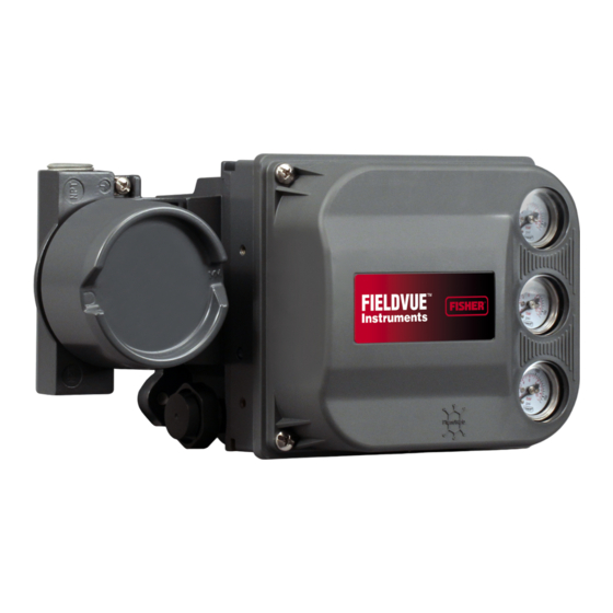
Fisher DVC6200 Mounting Instructions
Digital valve controller
on 1061 size 80-100 actuator
(window mount)
Hide thumbs
Also See for DVC6200:
- Instruction manual (148 pages) ,
- Quick start manual (44 pages) ,
- Mounting instructions (8 pages)
Advertisement
Quick Links
M
ounting Instructions
D103452X012
May 2010
Use these instructions to mount a Fisher
DVC6200 digital valve
controller
80-100 actuator.
Avoid personal injury or property damage from
sudden release of process pressure or bursting of
parts. Before performing any installation
operations:
Always wear protective clothing, gloves, and
eyewear.
Do not remove the actuator from the valve while
the valve is still pressurized.
Disconnect any operating lines providing air
pressure, electric power, or a control signal to
the actuator. Be sure the actuator cannot
suddenly open or close the control valve.
Use bypass valves or completely shut off the
process to isolate the control valve from
process pressure. Relieve process pressure
from both sides of the control valve.
Vent the pneumatic actuator loading pressure
and relieve any actuator spring
precompression.
Use lock-out procedures to be sure that the
above measures stay in effect while you work
on the equipment.
Check with your process or safety engineer for
any additional measures that must be taken to
protect against process media.
Refer to figure 3 for mounting parts identification for
1061 Size 80-100. Refer to the DVC6200 digital valve
controller instruction manual for parts identification.
Refer to the appropriate actuator instruction manual for
actuator installation, operation, maintenance, and parts
identification.
1. Isolate the control valve from the process line
pressure and release pressure from both sides of the
valve body. Shut off all pressure lines to the actuator,
releasing all pressure from actuator.
Use lock-out procedures to be sure that the above
measures stay in effect while you work on the
equipment.
______________________________________________________________________________________________________
w
ww.Fisher.com
DVC6200 Digital Valve Controller
®
FIELDVUE™
on Fisher 1061, size
on 1061 Size 80-100 Actuator
2. Remove the cover plate screws and cover plate from
the actuator, if present.
3. Install the cam (key 1) on to the lever of the actuator. It
is necessary for use of arced feedback mechanism.
Consult with the appropriate actuator instruction manual
for proper actuator disassembly and reassembly.
4. Attach the cam (key 1) to the lever arm of the actuator
using hex head cap screws (key 2).
Ensure that the cam is oriented as shown in figure 3.
5. Detach the roller assembly from the arced feedback
arm.
6. Refer to figure 2, attach the follower arm extension
(key 3) to the arc feedback arm using hex head cap
screws (key 4), lock spring washers (key 5) and hex nuts
(key 6).
7. Attach the roller assembly to the follower arm
extension (key 3) as shown in figure 2.
8. Attach the digital valve controller to the arced feedback
assembly (key 7) as per the actuator requirement using
hex socket cap screws (key 8).
9. Attach the arced feedback assembly (key 3), along with
the digital valve controller to the yoke of actuator using
hex socket cap screws (key 9) as shown in figure 3.
10. Ensure that the roller of arced feedback assembly is
centered and resting on the cam surface.
11. Make pneumatic and electrical connections to the
digital valve controller as described in the digital valve
controller instruction manual.
12. It may be necessary to fine tune the placement of the
cam so that the digital valve controller receives the proper
feedback.
13. Setup and calibrate the digital valve controller as
described in the digital valve controller instruction manual
or quick start guide.
For additional information concerning mounting, setup,
calibration, and maintenance of the DVC6200 digital
valve controller, refer to the appropriate instruction
manual.
(Window Mount)
Advertisement

Related Manuals for Fisher DVC6200


Summary of Contents for Fisher DVC6200
- Page 1 Refer to figure 3 for mounting parts identification for controller instruction manual. 1061 Size 80-100. Refer to the DVC6200 digital valve controller instruction manual for parts identification. 12. It may be necessary to fine tune the placement of the...
- Page 2 DVC6200 Digital Valve Controller Mounting Instructions on 1061 Size 80-100 Actuator D103452X012 (Window Mount) May 2010 Note Neither Emerson, Emerson Process Management, nor any of their affiliated entities assumes responsibility for the selection, use or maintenance of any product. Responsibility for the selection, use and maintenance of any product remains with the purchaser and end user.
- Page 3 NO.10 SIZE HEX NUTS ARCED FEEDBACK ASSEMBLY M8X1.25X16 SOCKET SCREWS 5/16-18X0.62 SOCKET SCREWS *NOTE: The DVC6200 uses 4 M8 socket screws (key 8) for mounting onto arced feedback assembly. 1061 Size 80-100 Actuator with DVC6200 Digital Valve Controller Figure 3. Mounting Parts Identification...
- Page 4 May 2010 Fisher and FIELDVUE are marks owned by one of the companies in the Emerson Process Management business division of Emerson Electric Co. Emerson Process Management, Emerson, and the Emerson logo are trademarks and service marks of Emerson Electric Co. All other marks are the property of their respective owners.