Fisher FIELDVUE DVC6200 Instruction Manual
Digital valve controller
Hide thumbs
Also See for FIELDVUE DVC6200:
- Instruction manual (116 pages) ,
- Quick start manual (44 pages) ,
- Mounting instructions (8 pages)
Table of Contents
Advertisement
Instruction Manual
D103409X012
Fisherr FIELDVUE
Controller
This manual applies to
Instrument Level
HC, AD, PD, ODV
Device Type
03
Device Revision
2
Hardware Revision
1
Firmware Revision
9, 10 & 11
DD Revision
8
. . . . . . . . . . . . . . . . . . . . . . . . . . . . .
. . . . . . . . . . . . . . . . . . . . . . . . . . . . . . . . .
. . . . . . . . . . . . . . . . . . . . . . . . . . . . . . .
. . . . . . . . . . . . . . . . . . . . . . . . . .
. . . . . . . . . . . . . . . . . . . . . . . . .
over 210 mm (8 Inches) Travel
. . . . . . . . . . . . . . . . . . . . . . . . . . .
. . . . . . . . . . . . . . . . . . . . . . . . . . . . . . . . . . .
. . . . . . . . . . . . . . . . . . . . . . . . . . . . . . . . . . . .
. . . . . . . . . . . . . . . . . . . . . . . . . . . . . . . . . .
. . . . . . . . . . . . . . . . . . . . . . . . . . . . .
. . . . . . . . . . . . . . . . . . . . . . . . . . . . .
www.Fisher.com
™
DVC6200 Digital Valve
AC
07
2
1
9, 10 & 11
1
. . . . . . . . . . . . . . . . .
. . . . . . . . . . . . . . .
. . . . . . . . . . . . . . . . .
. . . . . . . . . . . . . . . . . . . . .
. . . . . . . . . . . . .
. . . . . . . . .
. . . . . . . . . . . .
. . . . . . . . . .
. . . . . . . . . . . .
. . . . . . . .
. . . . . . . . . . . . . . . . . . . . . . .
. . . . . . . . . . . . . . . . . . . . . .
. . . . . . . . . . . . . . . .
. . . . . . . . . . . . . .
. . . . . . . . . . . . . . . . . . .
. . . . . . . . . . . .
. . . . . . . . . . . . . . . .
. . . . . . . . . . . . . . . . . . . . . . .
. . . . . . . . . . . . . . . . . . . . .
3
3
3
4
W9713
5
8
9
11
11
14
16
18
20
22
25
26
26
26
27
28
29
30
30
31
32
34
34
34
35
37
DVC6200 Digital Valve Controller
. . . . . . . . . . . . . . . . .
. . . . . . . . . . . . . . . . . . . . . . . . .
. . . . . . . . . . . . . . . . .
. . . . . . . . . . . . . . . . . . . . . . . . . . .
. . . . . . . . . . . . . . . . . . . .
. . . . . . . . . . . . . . . . . . . . . . . . . . . . . . . .
. . . . . . . . . . . . . . . . . . . . . . . . . . .
. . . . . . . . . . . . . . . . . . . . . .
. . . . . . . . . . . . . .
. . . . . . . . . . . . . . . . . . . . . . . .
. . . . . . . . . . . . . . . . . . . . . . . . . . . . . . . . .
. . . . . . . . . . . . . . . . . . . . . . . . . . . . .
. . . . . . . . . . . . . . . . . . . . . . . . . . . . . . . .
. . . . . . . . . . . . . . . . . . . . . . . . .
. . . . . . . . . . . . . . . . . . . . . .
. . . . . . . . . . . . . . . . . . . . . .
. . . . . . . . . . . . . . . . . .
. . . . . . . . . . . . . . . . . . .
. . . . . . . . . . . . . . . . . . . . . .
May 2013
37
38
41
41
41
42
42
44
. . . . .
45
47
49
49
50
. . . . . . . .
52
52
52
55
55
56
58
. . . . . . . . . . .
58
59
Advertisement
Chapters
Table of Contents
Troubleshooting

Related Manuals for Fisher FIELDVUE DVC6200


Summary of Contents for Fisher FIELDVUE DVC6200
-
Page 1: Table Of Contents
......Mounting Fisher 67CFR Filter Regulator .. -
Page 2: Contents
....The FIELDVUE DVC6200 Digital Valve Controller is a core component of the PlantWeb™ digital plant architecture. The digital valve controller powers PlantWeb by capturing and delivering valve diagnostic data. -
Page 3: Section 1 Introduction
This instruction manual describes using the 475 Field Communicator with device description revisions 1 and 2 to setup and calibrate the instrument. You can also use Fisher ValveLink software version 10.2 or higher to setup, calibrate, and diagnose the valve and instrument. For information on using ValveLink software with the instrument refer to ValveLink software help or documentation. -
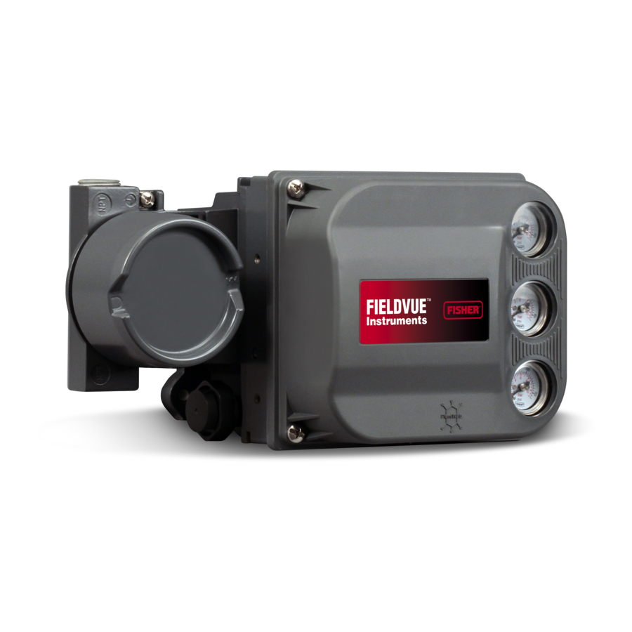
Page 4: Description
Figure 1‐1. FIELDVUE DVC6200 Digital Valve Figure 1‐2. FIELDVUE DVC6200 Digital Valve Controller Mounted on a Fisher Sliding-Stem Valve Controller Integrally Mounted to a Fisher GX Control Actuator Valve W9616 W9643 Diagnostic information is available to aid you when troubleshooting. -
Page 5: Specifications
Lead/Lag Set Point Filter 1. Refer to brochure part # D351146X012/D351146X412 for information on Fisher optimized digital valves for compressor antisurge applications. Using the HART protocol, information from the field can be integrated into control systems or be received on a single loop basis. - Page 6 Output Signal DVC6200 digital valve controller or DVC6215 Pneumatic signal, up to 95% of supply pressure feedback unit: J Integral mounting to the Fisher GX Minimum Span: 0.4 bar (6 psig) Control Valve and Actuator System J Window Maximum Span: 9.5 bar (140 psig) mounting to Fisher rotary actuators J Sliding‐stem...
- Page 7 Instruction Manual Introduction D103409X012 May 2013 Table 1‐2. Specifications (continued) Vibration Testing Method TIIS— Technology Institution of Industrial Safety (Japan) Tested per ANSI/ISA-S75.13.01 Section 5.3.5. A resonant frequency search is performed on all three Contact your Emerson Process Management sales axes.
-
Page 8: Related Documents
D Bulletin 62.1:DVC6200(S1) Fisher FIELDVUE DVC6200 Digital Valve Controller Dimensions (D103543X012) D Fisher FIELDVUE DVC6200 Series Digital Valve Controller Quick Start Guide (D103556X012) D FIELDVUE Digital Valve Controller Split Ranging - Supplement to HART Communicating Fisher FIELDVUE Digital Valve Controller Instruction Manuals (D103262X012) D Using FIELDVUE Instruments with the Smart HART Loop Interface and Monitor (HIM) - Supplement to HART... -
Page 9: Educational Services
Introduction D103409X012 May 2013 D HART Field Device Specification - Supplement to Fisher FIELDVUE DVC6000 and DVC6200 HW1 Digital Valve Controller Instruction Manuals (D103649X012) D Using the HART Tri‐Loop HART‐to‐Analog Signal Converter with FIELDVUE Digital Valve Controllers - Supplement to HART Communicating FIELDVUE Instrument Instruction Manuals (D103267X012) D Lock‐in‐Last Strategy - Supplement to Fisher FIELDVUE DVC6000 or DVC6200 Digital Valve Controller Instruction... - Page 10 Instruction Manual Introduction May 2013 D103409X012...
-
Page 11: Section 2 Installation
The DVC6200 housing is available in two different configurations, depending on the actuator mounting method. Figure 2‐1 shows the available configurations. Figure 2‐1. Housing Configurations HOUSING FOR HOUSING FOR LINEAR AND ROTARY ACTUATORS FISHER GX ACTUATORS INTEGRAL OUTPUT PRESSURE PORT ROTARY NAMUR, M6 HOLE FOR SLOTS FOR... - Page 12 Instruction Manual Installation May 2013 D103409X012 The feedback system for the DVC6200 digital valve controller utilizes a magnetic assembly for linkage‐less, non‐contacting position measurement. In order to prevent inadvertent stem movement while the instrument is in operation, magnetic tools (such as a magnetic‐tipped screwdriver) should not be used. Note The magnet assembly may be referred to as a magnetic array in user interface tools.
- Page 13 Each mounting kit includes detailed information on mounting the digital valve controller to a specific actuator. Refer to table 2‐1 for the more common Fisher actuator mounting instructions, available at www.fisher.com or your Emerson Process Management sales office.
-
Page 14: Mounting The Dvc6205 Base Unit
Installation May 2013 D103409X012 For general mounting guidelines, refer to the DVC6200 Series quick start guide (D103556X012), available at www.fisher.com or your Emerson Process Management sales office. Table 2‐1. DVC6200 Mounting Instructions Instructions for Mounting: Part Number 585C/585CR Size 25 Actuator with or without Handjack... - Page 15 Instruction Manual Installation D103409X012 May 2013 Figure 2‐4. FIELDVUE DVC6205 Base Unit with Mounting Bracket (Rear View) (2.25) (2.82) 2 MOUNTING HOLES j 8.6 (0.34) 10C1796‐A (INCH) Figure 2‐5. FIELDVUE DVC6205 Base Unit Wall Mounting SPACER 1‐INCH 1/4‐20 HEX HEAD SCREW MOUNTING BRACKET X0428...
-
Page 16: Mounting The Dvc6215 Feedback Unit
(such as a magnetic‐tipped screwdriver) should not be used. Figure 2‐7. Feedback Unit Housing Configurations HOUSING FOR HOUSING FOR LINEAR AND ROTARY ACTUATORS FISHER GX ACTUATORS INTEGRAL OUTPUT PRESSURE PORT ROTARY NAMUR, M6 HOLES FOR LINEAR, M8... - Page 17 Instruction Manual Installation D103409X012 May 2013 CAUTION The magnet assembly material has been specifically chosen to provide a long‐term stable magnetic field. However, as with any magnet, care must be taken when handling the magnet assembly. Another high powered magnet placed in close proximity (less than 25 mm) can cause permanent damage.
-
Page 18: Sliding-Stem Linear Actuators Up To 210 Mm (8 Inches) Of Travel
However, despite subtle differences in fasteners, brackets, and connecting linkages, the procedures for mounting can be categorized as follows: D Sliding‐stem linear actuators D Fisher rotary actuators D GX actuator D Quarter‐turn actuators See figure 2‐3 for examples of the different travel feedback magnet assemblies. - Page 19 5. Align the magnet assembly as follows: For air‐to‐open actuators (e.g. Fisher 667) vertically align the magnet assembly so that the center line of the alignment template is lined up as close as possible with the upper extreme of the valid travel range on the magnet assembly. The magnet assembly should be positioned so that the index mark in the feedback slot of the DVC6215 housing is within the valid range on the magnet assembly throughout the range of travel.
-
Page 20: Fisher Rotary Actuators And Sliding-Stem Linear Actuators
Ensure that there is clearance between the magnet assembly and the DVC6215 housing slot throughout the full range of travel. Fisher Rotary Actuators and Sliding‐Stem Linear Actuators over 210 mm (8.25 Inches) Travel The DVC6215 feedback unit uses a cam (designed for linear response) and roller as the feedback mechanism. See figures 2‐12 and 2‐13. - Page 21 Instruction Manual Installation D103409X012 May 2013 2. Verify that the appropriate cam is installed on the actuator as described in the instructions included with the mounting kit. 3. Mount the DVC6215 on the actuator as follows: D If required, a mounting adaptor is included in the mounting kit. Attach the adaptor to the feedback unit, then attach the feedback unit assembly to the actuator.
-
Page 22: Gx Actuators
Instruction Manual Installation May 2013 D103409X012 Sliding‐Stem Linear Actuators over 210 mm (8.25 Inches) Travel Refer to the following guidelines when mounting on sliding‐stem linear actuators over 210 mm (8.25 inches) travel (see figure 2‐13). 1. Isolate the control valve from the process line pressure and release pressure from both sides of the valve body. Shut off all pressure lines to the pneumatic actuator, releasing all pressure from the actuator. - Page 23 8. Connect the pneumatic tubing from the DVC6205 to the feedback units pneumatic port provided on the front of the DVC6215 as shown in figure 2‐17. Figure 2‐17. Modifications for Fisher GX Actuator; Air‐to‐Open Construction Only PNEUMATIC TUBING FROM THE DVC6205 PNEUMATIC PORT INSTALL O‐RING...
- Page 24 Instruction Manual Installation May 2013 D103409X012 9. Check for clearance between the magnet assembly and the DVC6215 feedback slot. 10. If not already installed, install a vent in the port on the upper diaphragm casing's air supply connection on the actuator yoke leg.
-
Page 25: Quarter-Turn Rotary Actuators
Instruction Manual Installation D103409X012 May 2013 Quarter‐Turn Rotary Actuators The DVC6215 feedback unit can be mounted to any quarter‐turn rotary actuator, as well as those that comply with the NAMUR guidelines. A mounting bracket and associated hardware are required. Refer to figure 2‐18. 1. -
Page 26: Mounting Fisher 67Cfr Filter Regulator
Attach the 67CFR filter regulator to the side of the digital valve controller. Thread a 1/4‐inch socket‐head pipe plug into the unused outlet on the filter regulator. This is the standard method of mounting the filter regulator. Figure 2‐20. Mounting the Fisher 67CFR Regulator on a FIELDVUE DVC6200 Digital Valve Controller OUTPUT A (1/4 NPT) -
Page 27: Supply
Instruction Manual Installation D103409X012 May 2013 Figure 2‐21. Pressure Connections LOOP CONNECTIONS TERMINAL BOX OUTPUT A CONNECTION 1/2 NPT WIRING TERMINAL BOX FEEDBACK X0379 W9615 CONNECTIONS TERMINAL BOX OUTPUT B SUPPLY CONNECTION CONNECTION DVC6205 BASE UNIT VALVE MOUNTED UNIT Supply WARNING To avoid personal injury or property damage resulting from bursting of parts, do not exceed maximum supply pressure. -
Page 28: Output Connection
Instruction Manual Installation May 2013 D103409X012 D Ensure that the cover is correctly installed before putting this unit back into service. Failure to do so could result in personal injury or property damage from fire or explosion. The DVC6200 can be used with air or natural gas as the supply medium. If using natural gas as the pneumatic supply medium, natural gas will be used in the pneumatic output connections of the DVC6200 to any connected equipment. -
Page 29: Special Construction To Support Solenoid Valve Testing
Instruction Manual Installation D103409X012 May 2013 Double‐Acting Actuators DVC6200 digital valve controllers on double‐acting actuators always use relay A. With no input current, OUTPUT A is at 0 pressure and OUTPUT B is at full supply pressure when the relay is properly adjusted. To have the actuator stem extend from the cylinder with increasing input signal, connect OUTPUT A to the upper actuator cylinder connection. -
Page 30: Vent
Instruction Manual Installation May 2013 D103409X012 Vent WARNING Personal injury or property damage can occur from cover failure due to overpressure. Ensure that the housing vent opening is open and free of debris to prevent pressure buildup under the cover. WARNING This unit vents the supply medium into the surrounding atmosphere. -
Page 31: 4-20 Ma Loop Connections
Instruction Manual Installation D103409X012 May 2013 Personal injury or property damage caused by fire or explosion may occur if this connection is attempted in a potentially explosive atmosphere or in an area that has been classified as hazardous. Confirm that area classification and atmosphere conditions permit the safe removal of the terminal box cover before proceeding. -
Page 32: Remote Travel Sensor Connections
Instruction Manual Installation May 2013 D103409X012 WARNING Personal injury or property damage, caused by fire or explosion, can result from the discharge of static electricity. Connect a 14 AWG (2.08 mm ) ground strap between the digital valve controller and earth ground when flammable or hazardous gases are present. - Page 33 Instruction Manual Installation D103409X012 May 2013 Figure 2‐25. Terminal Details for Connecting the Base Unit and Feedback Unit for Remote‐Mounted Digital Valve Controllers FEEDBACK CONNECTIONS TERMINAL BOX X0131 X0132 FEEDBACK UNIT GROUND BASE UNIT SCREW TO FEEDBACK UNIT TERMINAL 1 TO FEEDBACK UNIT TERMINAL 2 TO FEEDBACK UNIT TERMINAL 3 TO FEEDBACK UNIT TERMINAL 4...
-
Page 34: Wiring Practices
Instruction Manual Installation May 2013 D103409X012 CAUTION Failure to secure the cable wires in the support clips in step 9 can result in broken wires in applications with high levels of vibration. 9. Secure the cable wires, using the support clips in the DVC6215 feedback unit (as shown in figure 2‐26), to help prevent shifting and movement of the wires. -
Page 35: Voltage Available
Instruction Manual Installation D103409X012 May 2013 Figure 2‐27. HART Filter Application NON‐HART BASED DCS HART FILTER 4‐20 mA + HART DIGITAL VALVE CONTROLLER VALVE A6188‐1 Voltage Available The voltage available at the DVC6200 digital valve controller must be at least 11 volts DC. The voltage available at the instrument is not the actual voltage measured at the instrument when the instrument is connected. - Page 36 Instruction Manual Installation May 2013 D103409X012 Figure 2‐28. Determining Voltage Available at the Instrument TOTAL LOOP THUM ADAPTER CABLE RESISTANCE (IF USED) COMPLIANCE VOLTAGE CONTROL SYSTEM VOLTAGE INTRINSIC SAFETY AVAILABLE AT THE HART FILTER BARRIER INSTRUMENT (if used) (if used) Calculate Voltage Available at the Instrument as follows: Example Calculation 18.5 volts (at 21.05 mA)
-
Page 37: Compliance Voltage
Instruction Manual Installation D103409X012 May 2013 Compliance Voltage If the compliance voltage of the control system is not known, perform the following compliance voltage test. 1. Disconnect the field wiring from the control system and connect equipment as shown in figure 2‐29 to the control system terminals. -
Page 38: Installation In Conjunction With A Rosemountt 333 Hart Tri-Loopt Hart-To-Analog Signal Converter
Instruction Manual Installation May 2013 D103409X012 Length(ft) = [160,000 - 50,000pF] [50pF/ft] Length = 2200 ft. The HART communication cable length is limited by the cable characteristic capacitance. To increase cable length, select a wire with lower capacitance per foot. Contact your Emerson Process Management sales office for specific information relating to your control system. - Page 39 Instruction Manual Installation D103409X012 May 2013 Commissioning the Digital Valve Controller for use with the HART Tri‐Loop Signal Converter To prepare the digital valve controller for use with a 333 HART Tri‐Loop, you must configure the digital valve controller to burst mode, and select Burst Command 3. In burst mode, the digital valve controller provides digital information to the HART Tri‐Loop HART‐to‐Analog Signal Converter.
- Page 40 Instruction Manual Installation May 2013 D103409X012...
-
Page 41: Section 3 Basic Setup
Instruction Manual Basic Setup D103409X012 May 2013 Section 3 Basic Setup33 Instrument Mode Hot Key > Instrument Mode (Hot Key‐1) Field Communicator Configure > Detailed Setup > Mode and Protection > Instrument Mode ( 1‐2‐1‐1 ) To setup and calibrate the instrument, the instrument mode must be Out Of Service. If the mode is not Out Of Service, select Out Of Service from the Instrument Mode menu and press ENTER. -
Page 42: Basic Setup
Instruction Manual Basic Setup May 2013 D103409X012 Basic Setup Field Communicator Configure > Guided Setup (1‐1) WARNING Changes to the instrument setup may cause changes in the output pressure or valve travel. Depending on the application, these changes may upset process control, which may result in personal injury or property damage. Note To setup and calibrate the instrument, the protection must be None and the Instrument Mode must be Out Of Service. - Page 43 Instruction Manual Basic Setup D103409X012 May 2013 Table 3‐1. Factory Default Settings Setup Parameter Default Setting Analog Input Units Analog In Range High 20.0 mA Analog In Range Low 4.0 mA Control Mode Analog (Digital if Multidrop) Restart Control Mode Resume Last Self‐Test Shutdown All Failures Disabled...
-
Page 44: Performance Tuner
The Performance Tuner is used to optimize digital valve controller tuning. It can be used with digital valve controllers mounted on most sliding‐stem and rotary actuators, including Fisher and other manufacturers' products. Moreover, because the Performance Tuner can detect internal instabilities before they become apparent in the travel response, it can generally optimize tuning more effectively than manual tuning. -
Page 45: Stabilizing/Optimizing Valve Response
Instruction Manual Basic Setup D103409X012 May 2013 Stabilizing/Optimizing Valve Response Hot Key > Stabilize/Optimize (Hot Key‐4) Field Communicator Instrument level HC only Configure > Guided Setup > Stabilize/Optimize (1‐1‐2) Note Stabilize/Optimize is available for instrument level HC, AD, PD, and ODV. WARNING During Stabilize/Optimize the valve may move, causing process fluid or pressure to be released. - Page 46 Instruction Manual Basic Setup May 2013 D103409X012...
-
Page 47: Section 4 Detailed Setup
Instruction Manual Detailed Setup D103409X012 May 2013 Section 4 Detailed Setup Detailed Setup Field Communicator Configure > Detailed Setup (1‐2) Note Detailed Setup is available for instrument level HC, AD, PD, and ODV. Detailed Setup allows you to configure the digital valve controller to your application. Table 4‐1 lists the default settings for a standard factory configuration. - Page 48 Instruction Manual Detailed Setup May 2013 D103409X012 Table 4‐1. Default Detailed Setup Parameters (continued) Setup Parameter Default Setting Cycle Counter Alert Enable Cycle Counter Alert Deadband Cycle Counter Alert Point 1000000 Travel History Alerts Travel Accumulator Alert Enable Travel Accumulator Deadband Travel Accumulator Alert Point 1000000 Travel Deviation Alert Enable...
-
Page 49: Mode And Protection
Instruction Manual Detailed Setup D103409X012 May 2013 Mode and Protection Mode Instrument Mode Hot Key > Instrument Mode (Hot Key‐1) Field Communicator Configure > Detailed Setup > Mode and Protection > Instrument Mode (1‐2‐1‐1) Instrument Mode allows you to either take the instrument Out Of Service or place it In Service. Taking the instrument Out Of Service allows you to perform instrument calibration and also allows you to change setup variables that affect control, provided the calibration/configuration protection is properly set. -
Page 50: Protection
Instruction Manual Detailed Setup May 2013 D103409X012 the instrument is in burst mode. Between each burst mode transmission sent by the instrument, a short pause allows the Field Communicator or control system to initiate a request. The instrument receives the request, processes the response message, and then continues “bursting”... - Page 51 If necessary, temporarily attach the jumper to the AUX + and AUX - terminals in the instrument terminal box when prompted by the Field Communicator. Table 4‐2. Conditions for Modifying FIELDVUE DVC6200 Digital Valve Controller Parameters In Service/ In Service/...
-
Page 52: Protection And Response Control
Instruction Manual Detailed Setup May 2013 D103409X012 Table 4‐2. Conditions for Modifying FIELDVUE DVC6200 Digital Valve Controller Parameters (continued) In Service/ In Service/ Out of Service/ Out of Service/ Parameters Config Protected Config Unprotected Config Protected Config Unprotected Tvl Dev Alrt Enab... - Page 53 Stabilize/Optimize or Performance Tuner may be used to achieve the desired results more rapidly than Expert tuning. Table 4‐4 provides tuning set selection guidelines for Fisher and Baumann actuators. These tuning sets are only recommended starting points. After you finish setting up and calibrating the instrument, you may have to select either a higher or lower tuning set to get the desired response.
- Page 54 (Window‐mount) 60, 70 Depends upon pneumatic connections. See 1061 Piston Dbl w/o Spring description for Travel Sensor Motion Fisher 68, 80, 100, 130 Mounting Style Travel Sensor Motion Away from the top of the instrument Towards the top of the...
-
Page 55: Integral Settings
The Performance Tuner is used to determine digital valve controller tuning. It can be used with digital valve controllers mounted on most sliding‐stem and rotary actuators, including Fisher and other manufacturers' products. Moreover, because the performance tuner can detect internal instabilities before they become apparent in the travel response, it can generally optimize tuning more effectively than manual tuning. -
Page 56: Travel/Pressure Control
Instruction Manual Detailed Setup May 2013 D103409X012 In addition, you can specify Expert tuning and individually set the pressure proportional gain, pressure integrator gain, and pressure minor loop feedback gain. Individually setting or changing any tuning parameter will automatically change the tuning set to X (expert). Note Use Expert tuning only if standard tuning has not achieved the desired results. - Page 57 Instruction Manual Detailed Setup D103409X012 May 2013 pressure, depending upon the zero power condition. A Travel Cutoff Low of 0.5% is recommended to help ensure maximum shutoff seat loading. When a Travel Cutoff Low is set, the Travel Limit Low is deactivated, since only one of these parameters can be active.
-
Page 58: Input Characterization
Instruction Manual Detailed Setup May 2013 D103409X012 D Press Set Point—Used in conjunction with End Point Pressure Control, Pressure Set Point allows the user to select a pressure to be delivered by the instrument at the travel extreme. For a fail‐closed valve, this pressure must be sufficient to maintain the fully open position. -
Page 59: Dynamic Response
Instruction Manual Detailed Setup D103409X012 May 2013 Figure 4‐1. Travel Target Versus Ranged Set Point, for Various Input Characteristics (Zero Power Condition = Closed) Ranged Set Point, % Ranged Set Point, % Input Characteristic = Linear Input Characteristic = Equal Percentage Ranged Set Point, % Input Characteristic = Quick Opening A6535‐1/IL... -
Page 60: Alerts
Instruction Manual Detailed Setup May 2013 D103409X012 D Set Point Filter Time (Lag Time)—The Set Point Filter Time (Lag Time) slows the response of the digital valve controller. A value ranging from 0.2 to 10.0 can be used for noisy or fast processes to improve closed loop process control. -
Page 61: Electronics Alerts
Instruction Manual Detailed Setup D103409X012 May 2013 Zero Power Condition as per figure 4‐6. It will remain latched in that condition until power to the instrument is cycled and the failure alert has cleared. While in shutdown condition the instrument will remain powered up and able to communicate via HART. Shutdown alerts are turned off by default. -
Page 62: Sensor Alerts
Instruction Manual Detailed Setup May 2013 D103409X012 Sensor Alerts Field Communicator Configure > Detailed Setup > Alert Setup > Sensor Alerts (1‐2‐3‐2) Travel Sensor Shutdown—When enabled, the instrument shuts down whenever there is a failure associated with the travel sensor. Temp Sensor Shutdown—When enabled, the instrument shuts down whenever there is a failure associated with the temperature sensor. -
Page 63: Travel Alerts
Instruction Manual Detailed Setup D103409X012 May 2013 Travel Alerts Field Communicator Configure > Detailed Setup > Alert Setup > Travel Alerts (1‐2‐3‐4) Travel—Travel displays the actual position of the valve in percent (%) of calibrated travel. Setpoint—Setpoint is the input to the characterization function. Travel Alert DB—Travel Alert Deadband is the travel, in percent (%) of ranged travel, required to clear a travel alert, once it has been set. - Page 64 Instruction Manual Detailed Setup May 2013 D103409X012 D Travel Alert Hi Hi Point—The value of the travel, in percent (%) of ranged travel, which, when exceeded, sets the Travel Alert Hi Hi alert. D Travel Alert Lo Lo Point— The value of the travel, in percent (%) of ranged travel, which, when exceeded, sets the Travel Alert Lo Lo alert.
-
Page 65: Travel History Alerts
Instruction Manual Detailed Setup D103409X012 May 2013 D Travel Limit Lo—Defines the low limit for the travel in percent (%) of ranged travel. It is the minimum allowable travel (in percent of ranged travel) for the valve. During operation, the travel target will not exceed this limit. When a Travel Limit Low is set, the Travel Cutoff Low is deactivated, since only one of these parameters can be active. -
Page 66: Sis Alerts
Instruction Manual Detailed Setup May 2013 D103409X012 Travel Accumulator D Travel Accumulator Alert Enable—Yes or No. Activates checking of the difference between the Travel Accumulator value and the Travel Accumulator Alert Point. The Travel Accumulation Alert is set when the Travel Accumulator value exceeds the Travel Accumulator Alert Point. -
Page 67: Alert Record
Instruction Manual Detailed Setup D103409X012 May 2013 Alert Record HC, AD and PD Configure > Detailed Setup > Alert Setup > Alert Record (1‐2‐3‐6) Field Communicator Configure > Detailed Setup > Alert Setup > Alert Record (1‐2‐3‐7) To be recorded, an alert must both be enabled for reporting, and the group in which it resides must be enabled for recording. -
Page 68: Status
Instruction Manual Detailed Setup May 2013 D103409X012 Status Field Communicator Configure > Detailed Setup > Status (1‐2‐4) Follow the prompts on the Field Communicator display to configure the following parameters: Instrument Time, Calibration and Diagnostics, Operational, and Integrator. Instrument Time D Inst Time Invalid Enable—Yes or No. -
Page 69: Instrument
Instruction Manual Detailed Setup D103409X012 May 2013 Instrument Field Communicator Configure > Detailed Setup > Instrument (1‐2‐5) Follow the prompts on the Field Communicator display to configure the following Instrument parameters: General, Units, Analog Input Range, Relay Type, Zero Power Condition, Maximum Supply Pressure, Auxiliary Terminal Mode, Instrument Date and Time, and Calibration Status and Type. - Page 70 Instruction Manual Detailed Setup May 2013 D103409X012 Figure 4‐5. Calibrated Travel to Analog Input Relationship TRAVEL RANGE HIGH ZPC = OPEN ZPC = CLOSED THE SHAPE OF THESE LINES DEPENDS ON THE INPUT CHARACTERISTICS LINEAR TRAVEL CHARACTERISTIC SHOWN RANGE ANALOG INPUT mA OR % OF 4‐20 mA INPUT RANGE INPUT RANGE...
-
Page 71: Valve & Actuator
Instruction Manual Detailed Setup D103409X012 May 2013 Auxiliary Terminal Action —Disabled, Alert on Open Contact, Alert on Close Contact, or Auto Travel Calibration. Selecting Alert on Open or Closed Contact activates checking the status of the auxiliary input contacts. Selecting Auto Travel Calibration permits starting an automatic travel calibration procedure by placing a jumper across the auxiliary input terminals for 3 to 5 seconds. - Page 72 Instruction Manual Detailed Setup May 2013 D103409X012 D For instruments with Relay B: If decreasing air pressure at output B causes the magnet assembly to down, or the rotary shaft to turn clockwise, enter CW/To Bottom Inst. If it causes the magnet assembly to move up, or the rotary shaft to turn counterclockwise, enter CCW/To Top Inst.
-
Page 73: Partial Stroke
Instruction Manual Detailed Setup D103409X012 May 2013 SIS/Partial Stroke (Instrument Level ODV) Field Communicator Configure / Setup > Detailed Setup > SIS/Partial Stroke (1‐2‐7) Note Partial Stroke is only available for instrument level ODV. Follow the prompts on the Field Communicator display to configure the following partial stroke parameters: PST Enable, and View/Edit PST Variables. - Page 74 Instruction Manual Detailed Setup May 2013 D103409X012 To set the partial stroke pressure limit manually for single acting actuators select min pressure. Select min diff press for double acting actuators. Note In order to manually set the partial stroke pressure limit with the correct value, you must be able to run a valve signature test using ValveLink software.
- Page 75 Instruction Manual Detailed Setup D103409X012 May 2013 Table 4‐10. Estimates for Partial Stroke Pressure Limits Actuator Style Relay Type Zero Power Condition PST Starting Point Partial Stroke Pressure Limit Open Pmin - 0.25 * (Bench Set High - Bench Set Low) Closed Closed Pmax + 0.25 * (Bench Set High - Bench Set Low)
- Page 76 Instruction Manual Detailed Setup May 2013 D103409X012...
-
Page 77: Section 5 Calibration
Instruction Manual Calibration D103409X012 May 2013 Section 5 Calibration Calibration Overview When a DVC6200 digital valve controller is ordered as part of a control valve assembly, the factory mounts the digital valve controller on the actuator and connects the necessary tubing, then sets up and calibrates the controller. For digital valve controllers that are ordered separately, recalibration of the analog input or pressure sensors generally is unnecessary. -
Page 78: Travel Calibration
Instruction Manual Calibration May 2013 D103409X012 Travel Calibration Field Communicator Configure > Calibrate > Travel Calibration (1‐3‐1) If a double‐acting relay is used, you will be prompted to run the relay adjustment when auto or manual calibration is selected. Select Yes to adjust the relay, select No to proceed with calibration. For additional information, refer to Relay Adjustment in this section. -
Page 79: Manual Calibration
Instruction Manual Calibration D103409X012 May 2013 Manual Travel Calibration Two procedures are available to manually calibrate travel: D Analog Adjust D Digital Adjust Analog Calibration Adjust Connect a variable current source to the instrument LOOP + and LOOP - terminals. The current source should be capable of generating 4 to 20 mA. -
Page 80: Sensor Calibration
Instruction Manual Calibration May 2013 D103409X012 2. From the adjustment menu, select the direction and size of change required to set the travel at 0%. Selecting large, medium, and small adjustments causes changes of approximately 10.0%, 1.0%, and 0.1%, respectively. If another adjustment is required, repeat step 2. - Page 81 Instruction Manual Calibration D103409X012 May 2013 Output Pressure Sensor To calibrate the output pressure sensor, connect an external reference gauge to the output being calibrated. The gauge should be capable of measuring maximum instrument supply pressure. Depending upon the sensor you wish to calibrate, select either Output A Sensor or Output B Sensor.
-
Page 82: Analog Input Calibration
Instruction Manual Calibration May 2013 D103409X012 1. Select a) Zero Only, or b) Zero and Span (gauge required). a. If Zero Only calibration is selected, adjust the supply pressure regulator to remove supply pressure from the instrument. Press OK. Once calibration is complete, go to step 5. b. -
Page 83: Relay Adjustment
Instruction Manual Calibration D103409X012 May 2013 5. Set the current source to the target value shown on the display. The target value is the Input Range High value. Press OK. 6. The following message appears: Use Increase and Decrease selections until the displayed current matches the target. - Page 84 Instruction Manual Calibration May 2013 D103409X012 Figure 5‐1. Relay A Adjustment (Shroud Removed for Clarity) FOR SINGLE‐ACTING DIRECT RELAYS: ROTATE ADJUSTMENT DISC IN THIS DIRECTION UNTIL IT CONTACTS THE BEAM FOR DOUBLE‐ACTING RELAYS: ROTATE ADJUSTMENT DISC IN THIS DIRECTION TO DECREASE OUTPUT PRESSURE ADJUSTMENT DISC FOR DOUBLE‐ACTING RELAYS:...
-
Page 85: Single-Acting Relays
Instruction Manual Calibration D103409X012 May 2013 Single‐Acting Relays WARNING For Instrument Level ODV only: If the unused port is monitoring pressure, ensure that the pressure source conforms to ISA Standard 7.0.01 and does not exceed the pressure supplied to the instrument. Failure to do so could result in personal injury or property damage caused by loss of process control. - Page 86 Instruction Manual Calibration May 2013 D103409X012...
-
Page 87: Section 6 Viewing Device Variables And Diagnostics
Instruction Manual Viewing Device Variables and Diagnostics D103409X012 May 2013 Section 6 Viewing Device Variables and Diagnostics66 Service Tools Note Service Tools are not available for instrument level AC. Alert Conditions Field Communicator Service Tools > Alert Conditions (2‐1) Instrument Alert Conditions, when enabled, detect many operational and performance issues that may be of interest. To view these alerts navigate to Alert Conditions. - Page 88 Instruction Manual Viewing Device Variables and Diagnostics May 2013 D103409X012 Non‐Critical NVM Alert—This alert is indicated if the checksum for data, which are not critical for instrument operation, has failed. Critical NVM Alert—This alert is indicated when the Non‐Volatile Memory integrity test fails. Configuration data is stored in NVM.
- Page 89 Instruction Manual Viewing Device Variables and Diagnostics D103409X012 May 2013 Loop Current Validation Alert— This alert is activated if the loop current is out of valid range. If the control system is known to output currents outside of this range, the loop current shutdown should not be enabled. If this alert is indicated, clear the alert by restarting the instrument with the loop current verified to be in the valid range.
- Page 90 Instruction Manual Viewing Device Variables and Diagnostics May 2013 D103409X012 Viewing Instrument Status Field Communicator Service Tools > Status (2‐2) Status displays the status of the Operational items listed below. The status of more than one operational item may be indicated.
- Page 91 Instruction Manual Viewing Device Variables and Diagnostics D103409X012 May 2013 D Ramp to Target—ramps the travel to the specified target at the rate of 1.0% per second of the ranged travel. D Step to Target—steps the travel to the specified target. Partial Stroke Test (ODV only) Field Communicator Service Tools >...
- Page 92 Instruction Manual Viewing Device Variables and Diagnostics May 2013 D103409X012 Auxiliary Terminal Wiring Length Guidelines The Auxiliary Input Terminals of a DVC6200 with instrument level ODV can be used with a locally‐mounted switch for initiating a partial stroke test. Some applications require that the partial stroke test be initiated from a remote location.
-
Page 93: Overview
Instruction Manual Viewing Device Variables and Diagnostics D103409X012 May 2013 Overview Field Communicator Overview (3) The following menus are available to define and/or view information about the instrument. Note Overview is not available for instrument level AC. Analog In Analog Input shows the value of the instrument analog input in mA (milliamperes) or % (percent) of ranged input. Setpoint Setpoint shows the requested valve position in % of ranged travel post characterization. - Page 94 Instruction Manual Viewing Device Variables and Diagnostics May 2013 D103409X012 D Temperature—The internal temperature of the instrument is displayed in either degrees Fahrenheit or Celsius. D Maximum Recorded Temperature—Shows the maximum temperature the instrument has experienced since installation. D Minimum Recorded Temperature—Shows the minimum temperature the instrument has experienced since installation.
- Page 95 Instruction Manual Viewing Device Variables and Diagnostics D103409X012 May 2013 D Hardware Revision—The revision number of the electrical circuitry within the instrument printed wiring board. D Instrument Level—Indicates the instrument level AC—Auto Calibrate HC—HART Communicating AD—Advanced Diagnostics PD—Performance Diagnostics ODV—Optimized Digital Valve Table 6‐2 lists the functions available for each instrument level.
- Page 96 Instruction Manual Viewing Device Variables and Diagnostics May 2013 D103409X012...
-
Page 97: Section 7 Maintenance And Troubleshooting
Instruction Manual Maintenance and Troubleshooting D103409X012 May 2013 Section 7 Maintenance and Troubleshooting77 The DVC6200 digital valve controller enclosure is rated Type 4X and IP66, therefore periodic cleaning of internal components is not required. If the DVC6200 is installed in an area where the exterior surfaces tend to get heavily coated or layered with industrial or atmospheric contaminants, however, it is recommended that the vent (key 52) be periodically inspected to ensure it is fully open. -
Page 98: Replacing The Magnetic Feedback Assembly
Instruction Manual Maintenance and Troubleshooting May 2013 D103409X012 from fire or explosion if natural gas is used as the supply medium and appropriate preventive measures are not taken. Preventive measures may include, but are not limited to, one or more of the following: ensuring adequate ventilation and the removal of any ignition sources. -
Page 99: Component Replacement
Instruction Manual Maintenance and Troubleshooting D103409X012 May 2013 Component Replacement When replacing any of the components of the DVC6200, the maintenance should be performed in an instrument shop whenever possible. Make sure that the electrical wiring and pneumatic tubing is disconnected prior to disassembling the instrument. -
Page 100: Replacing The Module Base
Instruction Manual Maintenance and Troubleshooting May 2013 D103409X012 5. For the DVC6205 only, disconnect the cable assembly from the LOOP connections terminal box, as shown in figure 7‐2. Figure 7‐2. FIELDVUE DVC6205 Cable Connections CABLES FROM LOOP LOOP CONNECTIONS CONNECTIONS TERMINAL BOX TERMINAL BOX PRINTED WIRING BOARD ASSEMBLY... -
Page 101: Submodule Maintenance
Instruction Manual Maintenance and Troubleshooting D103409X012 May 2013 2. Connect the two cable assemblies from the sensor board to the PWB assembly (key 50). Orientation of the connector is required. 3. For DVC6205 only, connect the cable assembly from the LOOP connections terminal box to the Feedback Connections Terminal Box (see figure 7‐2). - Page 102 Instruction Manual Maintenance and Troubleshooting May 2013 D103409X012 Replacing the I/P Filter A screen in the supply port beneath the I/P converter serves as a secondary filter for the supply medium. To replace this filter, perform the following procedure: 1. Remove the I/P converter (key 41) and shroud (key 169) as described in the Removing the I/P Converter procedure. 2.
-
Page 103: Printed Wiring Board (Pwb) Assembly
Instruction Manual Maintenance and Troubleshooting D103409X012 May 2013 Figure 7‐4. I/P Converter SHROUD (KEY 169) I/P CONVERTER SOCKET‐HEAD (KEY 41) SCREWS (4) (KEY 23) BOOTS (KEY 210) W9328 3. Install the I/P converter (key 41) straight into the module base (key 2), taking care that the two electrical leads feed into the guides in the module base. - Page 104 Instruction Manual Maintenance and Troubleshooting May 2013 D103409X012 2. Properly orient the PWB assembly (key 50) as you install it into the module base. The two electrical leads from the I/P converter (key 41) must guide into their receptacles in the PWB assembly and the pressure sensor bosses on the module base must fit into their receptacles in the PWB assembly.
-
Page 105: Pneumatic Relay
Instruction Manual Maintenance and Troubleshooting D103409X012 May 2013 Pneumatic Relay Refer to figure 8‐2 or 8‐4 for key number locations. The pneumatic relay (key 24) is located on the front of the module base. Note After relay submodule replacement, calibrate the digital valve controller to maintain accuracy specifications. Removing the Pneumatic Relay 1. -
Page 106: Terminal Box
Instruction Manual Maintenance and Troubleshooting May 2013 D103409X012 Perform the following procedure to replace the gauges, tire valves, or pipe plugs. Refer to figure 8‐2 and 8‐3 for key number locations. 1. Remove the front cover (key 43). 2. Remove the gauge, pipe plug, or tire valve as follows: For gauges (key 47), the flats are on the gauge case. -
Page 107: Replacing The Terminal Box
Instruction Manual Maintenance and Troubleshooting D103409X012 May 2013 1. Loosen the set screw (key 58) in the cap (key 4) so that the cap can be unscrewed from the terminal box. 2. After removing the cap (key 4), note the location of field wiring connections and disconnect the field wiring from the terminal box. -
Page 108: Checking Loop Current
Instruction Manual Maintenance and Troubleshooting May 2013 D103409X012 To check the Voltage Available at the instrument, perform the following: 1. Connect the equipment in figure 2‐29 to the field wiring in place of the FIELDVUE instrument. 2. Set the control system to provide maximum output current. 3. - Page 109 Instruction Manual Maintenance and Troubleshooting D103409X012 May 2013 Table 7‐3. Instrument Troubleshooting Symptom Possible Cause Action 1. Analog input reading at 1a. Control mode not Analog. 1a. Check the control mode using the Field Communicator. If in instrument does not match the Digital or Test mode, the instrument receives its set point as actual current provided.
- Page 110 Instruction Manual Maintenance and Troubleshooting May 2013 D103409X012 Table 7‐3. Instrument Troubleshooting (Continued) Symptom Possible Cause Action 3b. Restricted pneumatic passages in I/P converter. 3j. Check screen in I/P converter supply port of the module base. Replace if necessary. If passages in I/P converter restricted, replace I/P converter.
- Page 111 Instruction Manual Maintenance and Troubleshooting D103409X012 May 2013 DVC6200 Technical Support Checklist Have the following information available prior to contacting your Emerson Process Management sales office for support. 1. Instrument serial number as read from nameplate ________________________________________________ 2. Is the digital valve controller responding to the control signal? Yes _________ No _________ If not, describe ___________________________________________________________________________ 3.
- Page 112 Instruction Manual Maintenance and Troubleshooting May 2013 D103409X012...
-
Page 113: Section 8 Parts
Use only genuine Fisher replacement parts. Components that are not supplied by Emerson Process Management should not, under any circumstances, be used in any Fisher instrument. Use of components not supplied by Emerson Process Management may void your warranty, might adversely affect the performance of the instrument, and could cause personal injury and property damage. -
Page 114: Parts List
Instruction Manual Parts May 2013 D103409X012 Description Part Number Description Part Number Screw, hex head (4 req’d) (DVC6205 only) 10* Feedback Array Kit, Aluminum Screw, hex head (4 req’d) (DVC6205 only) Spacer (4 req’d) (DVC6205 only) Sliding Stem (Linear) Standoff (2 req’d) (DVC6205 only) [kit contains feedback array and hex socket cap screws, qty. -
Page 115: I/P Converter Assembly
Instruction Manual Parts D103409X012 May 2013 Description Part Number Figure 8‐1. Terminal Box of Natural Gas Certified FIELDVUE DVC6200 Digital Valve Controller GAS‐BLOCKING PRESS‐FIT ADAPTOR I/P Converter Assembly (see figure 8‐2 and 8‐4) WIRING CONNECTOR DVC6200 and DVC6205 (2)(8) 23... -
Page 116: Pwb Assembly
Instruction Manual Parts D103409X012 May 2013 Description Description Part Number Pressure Gauges, Pipe Plugs, or Tire Valve Assemblies (see figure 8‐3) PWB Assembly (see figure 8‐2 and 8‐4) DVC6200 and DVC6205 47* Pressure Gauge, nickel‐plated brass case, brass connection DVC6200 and DVC6205 Double‐acting (3 req'd);... - Page 117 Instruction Manual Parts D103409X012 May 2013 Figure 8‐2. FIELDVUE DVC6200 Digital Valve Controller Housing Assembly HOUSING B—BACK VIEW HOUSING A—BACK VIEW (USED FOR ALL (USED FOR GX ACTUATOR) ACTUATORS EXCEPT GX) DOUBLE‐ACTING DIRECT‐ACTING REVERSE‐ACTING APPLY LUBRICANT, SEALANT, OR THREAD LOCK...
- Page 118 Instruction Manual Parts May 2013 D103409X012 Figure 8‐2. FIELDVUE DVC6200 Digital Valve Controller Housing Assembly (continued) SECTION C-C SCALE 2 : 1 SECTION A-A SECTION E-E SCALE 2 : 1 SECTION F-F APPLY LUBRICANT, SEALANT, OR THREAD LOCK SCALE 2 : 1...
- Page 119 Instruction Manual Parts D103409X012 May 2013 Figure 8‐4. FIELDVUE DVC6205 Base Unit Housing Assembly SECTION B-B SECTION A-A SECTION H-H APPLY LUBRICANT, SEALANT, OR THREAD LOCK APPLY LUBRICANT ON ALL O-RINGS UNLESS OTHERWISE SPECIFIED GE40181...
- Page 120 Instruction Manual Parts May 2013 D103409X012 Figure 8‐4. FIELDVUE DVC6205 Base Unit Housing Assembly (continued) SECTION C-C SCALE 2 : 1 SECTION E-E SCALE 2 : 1 DOUBLE‐ACTING SHOWN DOUBLE‐ACTING DIRECT‐ACTING REVERSE‐ACTING APPLY LUBRICANT, SEALANT, OR THREAD LOCK APPLY LUBRICANT ON ALL O-RINGS UNLESS OTHERWISE SPECIFIED GE40181...
- Page 121 Instruction Manual Parts D103409X012 May 2013 Figure 8‐4. FIELDVUE DVC6205 Base Unit Housing Assembly (continued) PIPE MOUNTING WALL MOUNTING APPLY LUBRICANT, SEALANT, OR THREAD LOCK APPLY LUBRICANT ON ALL O-RINGS UNLESS OTHERWISE SPECIFIED GE40181...
- Page 122 Instruction Manual Parts May 2013 D103409X012 Figure 8‐5. FIELDVUE DVC6215 Remote Feedback Assembly SECTION A-A PARTS NOT SHOWN: 158 APPLY LUBRICANT, SEALANT, OR THREAD LOCK GE46670-B HOUSING A (USED FOR GX ACTUATOR) SECTION A-A PARTS NOT SHOWN: 158 APPLY LUBRICANT, SEALANT, OR THREAD LOCK GE40178-B HOUSING B (USED FOR ALL ACTUATORS EXCEPT GX)
-
Page 123: Appendix A Principle Of Operation
Instruction Manual Principle of Operation D103409X012 May 2013 Appendix A Principle of OperationAA−A HART Communication The HART (Highway Addressable Remote Transducer) protocol gives field devices the capability of communicating instrument and process data digitally. This digital communication occurs over the same two‐wire loop that provides the 4‐20 mA process control signal, without disrupting the process signal. - Page 124 Instruction Manual Principle of Operation May 2013 D103409X012 Figure A‐2. Typical FIELDVUE Instrument to Personal Computer Connections for ValveLink Software CONTROL SYSTEM HART MODEM FIELD TERM. E1362 DVC6200 digital valve controllers are loop‐powered instruments that provide a control valve position proportional to an input signal from the control room.
- Page 125 Instruction Manual Principle of Operation D103409X012 May 2013 Figure A‐3. FIELDVUE DVC6200 Digital Valve Controller Block Diagram INPUT SIGNAL 4-20 mA HART VALVE TRAVEL FEEDBACK PRINTED WIRING BOARD DRIVE SIGNAL TERMINAL BOX OUTPUT A AUXILIARY TERMINALS PNEUMATIC CONVERTER RELAY SUPPLY PRESSURE...
- Page 126 Instruction Manual Principle of Operation May 2013 D103409X012...
-
Page 127: Appendix B Field Communicator Menu Tree
Instruction Manual Field Communicator Menu Trees D103409X012 May 2013 Appendix B Field Communicator Menu Trees This section contains the Field Communicator menu trees for instrument level HC, AD, PD, and ODV and instrument level AC. It also contains Fast Key Sequence tables with coordinates to help locate the function/variable on the appropriate menu tree. -
Page 128: Control Mode N N N N
Instruction Manual Field Communicator Menu Trees May 2013 D103409X012 Instrument Level HC, AD, PD, and ODV Fast‐Key Fast‐Key Function/Variable Coordinates Function/Variable Coordinates Sequence Sequence A minus B 3‐5‐3 4‐G Device Revision 3‐7‐5 2‐H Actuator Style 1‐2‐6‐4 3‐D Diagnostic Data Available Enable 1‐2‐4‐2‐4 8‐H Alert Conditions... - Page 129 Instruction Manual Field Communicator Menu Trees D103409X012 May 2013 Fast‐Key Fast‐Key Function/Variable Coordinates Function/Variable Coordinates Sequence Sequence 2‐3‐2 3‐F Status 2‐2 2‐F Minimum Recorded Temperature 3‐6‐4 4‐H Stroke Valve 2‐4 2‐F 1‐2‐3‐6‐5‐3 3‐5‐4 4‐G Miscellaneous Group Enable 10‐I Supply 1‐2‐3‐7‐5‐3 1‐2‐3‐3‐2‐2 12‐D Model...
-
Page 130: Message
Instruction Manual Field Communicator Menu Trees May 2013 D103409X012 Field Communicator Menu Tree for Instrument Level HC, AD, PD, and ODV 1‐2‐1‐4 Hot Key Burst Mode 1 Instrument Mode 1‐2‐1 1 Burst Enable 2 Control Mode Mode and Protection 2 Change Burst Enable 3 Protection 3 Burst Command 1 Instrument Mode 4 Stabilize/Optimize... - Page 131 Instruction Manual Field Communicator Menu Trees D103409X012 May 2013 1‐2‐2‐1‐1 Travel Tuning 1 Travel Tuning Set 2 Integral Enable 3 Integral Gain 4 Stabilize / Optimize 5 Performance Tuner 1‐2‐2‐1‐2 Integral Settings 1 Integral Dead Zone 2 Integ Limit 1‐2‐3‐1‐3 1‐2‐2‐1‐3 Processor Impaired Alerts 1‐2‐2‐2‐2 Pressure Tuning Cutoffs and Limits 1 Offline/Failed Alrt Enable 1 Pressure Tuning Set...
- Page 132 Instruction Manual Field Communicator Menu Trees May 2013 D103409X012 Instrument Level AC Fast‐Key Fast‐Key Function/Variable Coordinates Function/Variable Coordinates Sequence Sequence 1‐1‐2‐3‐2‐2 6‐D Actuator Style 1‐1‐2‐2‐4 4‐C Pressure Proportional Gain Analog Input Calibration 1‐3‐1 3‐F 1‐2‐3‐4‐1‐2 5‐H Pressure Range Hi 1‐2‐3‐5‐1 4‐G Analog Input Range Hi 1‐2‐2‐2...
-
Page 133: Valve Serial Num
Instruction Manual Field Communicator Menu Trees D103409X012 May 2013 Field Communicator Menu Tree for Instrument Level AC Hot Key 1 Instrument Mode 2 Protection 1‐1‐1 Auto Setup 1 Setup Wizard 1‐1‐2‐2 2 Relay Adjust Press & Actuator 3 Auto Travel Calib 1 Tvl/Press Select 2 Pressure Units 1‐1‐2 1‐1 3 Max Supply Press... - Page 134 Instruction Manual Field Communicator Menu Trees May 2013 D103409X012...
-
Page 135: Glossary
Instruction Manual Glossary D103409X012 May 2013 Glossary Alert Point Calibration Location An adjustable value that, when exceeded, Where the instrument was last calibrated; either activates an alert. in the factory or in the field. Algorithm Configuration A set of logical steps to solve a problem or Stored instructions and operating parameters for accomplish a task. - Page 136 Instruction Manual Glossary May 2013 D103409X012 Current‐to‐Pressure (I/P) Converter Drive Signal An electronic component or device that converts The signal to the I/P converter from the printed a milliamp signal to a proportional pneumatic wiring board. It is the percentage of the total pressure output signal.
- Page 137 Out of Service: The instrument output does not Hardware Revision change in response to analog input changes Revision number of the Fisher Controls when the instrument mode is Out of Service. instrument hardware. The physical components Some setup parameters can be changed only of the instrument are defined as the hardware.
- Page 138 Instruction Manual Glossary May 2013 D103409X012 Memory Pressure Sensor A type of semiconductor used for storing A FIELDVUE instrument internal device that programs or data. FIELDVUE instruments use senses pneumatic pressure. The DVC6200 has three types of memory: Random Access Memory three pressure sensors: one to sense supply (RAM), Read Only Memory (ROM), and pressure and two to sense the output pressures.
-
Page 139: Set Point Filter Time (Lag Time)
Instruction Manual Glossary D103409X012 May 2013 Seat Load Travel Accumulator Alert Force exerted on the valve seat, typically Checks the difference between the Travel expressed in pounds force per lineal inch of port Accumulator value and the Travel Accumulator circumference. Seat load is determined by shutoff Alert Point. - Page 140 Instruction Manual Glossary May 2013 D103409X012 Travel Alert High High Point Travel Deviation Alert Point Value of the travel, in percent of ranged travel, An adjustable value for the target travel and the which, when exceeded, sets the Travel Alert Hi Hi ranged travel difference, expressed in percent, alert.
- Page 141 Instruction Manual Glossary D103409X012 May 2013 Tuning Zero Power Condition The adjustment of control terms or parameter The position of the valve (open or closed) when values to produce a desired control effect. the electrical power to the instrument is removed.
- Page 142 Instruction Manual Glossary May 2013 D103409X012...
-
Page 143: Index
Instruction Manual Index D103409X012 May 2013 Index Auxiliary Input, 62 Auxiliary Terminal Partial Stroke Test, 91 Wiring Length Guidelines, 92 Auxiliary Terminal Action, 62 Auxiliary Terminal Alerts, 62 Actuator Compatibility, 7 Actuator Style, 71 Alert Conditions, 87 Basic Setup, 42 Alert Record, 89 Performance Tuner, 44 Electronics, 87... - Page 144 Instruction Manual Index May 2013 D103409X012 Descriptor, 69 Detailed Setup, 47 Gain Values Device Diagnostics, 87 Pressure Tuning Sets, 55 Travel Tuning Sets, 53 Device Record, 90 Gauges, maintenance, 105 Digital Calibration Adjust, 79 GOST-R, hazardous area approvals, 7 DIP Switch configuration, 104 setting, 103 Drive Signal Alert, 61...
- Page 145 Instruction Manual Index D103409X012 May 2013 Integral Setting, 55 Mode, 49 Burst, 49 Integrator Saturation, 68 Control, 49 ISA Standard 7.0.01, 28 Instrument, 41 Restart Control, 49 Module Base removing, 99 replacing, 100 jumper, 41 Module Base Maintenance, 98 Mounting 67CFR Regulator, 26 DVC6205 base unit KGS, hazardous area approvals, 7...
- Page 146 Instruction Manual Index May 2013 D103409X012 Pneumatic Connections, 26 Sensor Alerts, 62 Pressure, 26 Sensor Calibration, 80 Supply, 27 Special Construction to Support Solenoid Valve Serial Number Testing, 28, 29 Instrument, 69 Vent, 30 Valve, 69, 71 Pneumatic Relay Service Tools, 87 maintenance, 105 removing, 105 Set Point Filter Lag Time, 60...
- Page 147 Instruction Manual Index D103409X012 May 2013 Travel, 63 Troubleshooting Checking the Loop Current Without Disturbing the Alert Conditions, 89 Loop Wiring, 108 Alerts Checking Voltage Available, 107 Travel Limit Alerts, 63 instrument, 109 Travel Limit Hi/Lo Alerts, 64 Tuning Travel Accumulation Alert, 66 Integral Settings, 55 Pressure, 55 Travel Alerts, 63...
- Page 148 Responsibility for proper selection, use, and maintenance of any product remains solely with the purchaser and end user. Fisher, FIELDVUE, ValveLink, PlantWeb, PROVOX, Rosemount, Tri-Loop, DeltaV, RS3, and THUM are marks owned by one of the companies in the Emerson Process Management business unit of Emerson Electric Co.