Fisher FIELDVUE DVC6200 Instruction Manual
Digital valve
controller
Hide thumbs
Also See for FIELDVUE DVC6200:
- Instruction manual (148 pages) ,
- Quick start manual (44 pages) ,
- Mounting instructions (8 pages)
Table of Contents
Advertisement
Quick Links
Instruction Manual
D103605X012
™
Fisher
FIELDVUE
Controller
This manual applies to
Instrument Level
Device Type
Device Revision
Hardware Revision
Firmware Revision
DD Revision
Contents
. . . . . . . . . . . . . . . . . . . . . . . . . . . . . .
. . . . . . . . . . . . . . . . . . . . . . . . . . . . . . . . . .
. . . . . . . . . . . . . . . . . . . . . . . . . . . . . . . .
. . . . . . . . . . . . . . . . . . . . . . . . . . .
. . . . . . . . . . . . . . . . . . . . . . . . . . .
. . . . . . . . . . . . . . . . . . . . . . . . . . . . . . . . .
. . . . . . . . . . . . . . . . . . . . . . . . . . . .
. . . . . . . . . . . . . . . . . . . . . . . .
. . . . . . . . . . . . . . . . . . . . . . . . .
. . . . . . . . . . . . . . . . . . . . . . . . . . . . . . .
. . . . . . . . . . . . . . . . . . . . . . . . . . . . . . .
. . . . . . . . . . . . . . . . . . . . . . . .
. . . . . . . . . . . . . . . . . . . . . . . .
. . . . . . . . . . . . . . . . . . . . . . . . . . . . . . . .
. . . . . . . . . . . . . . . . . . . . . . . . . . .
. . . . . . . . . . . . . . . . . . . . . . . . .
. . . . . . . . . . . . . . . . . . . . . . . . . . . . . . . . . .
. . . . . . . . . . . . . . . . . . . . . . . . . . .
. . . . . . . . . . . . . . . . . . . . . . . . . . . .
. . . . . . . . . . . . . . . . . . . . . . . . . . . . .
www.Fisher.com
™
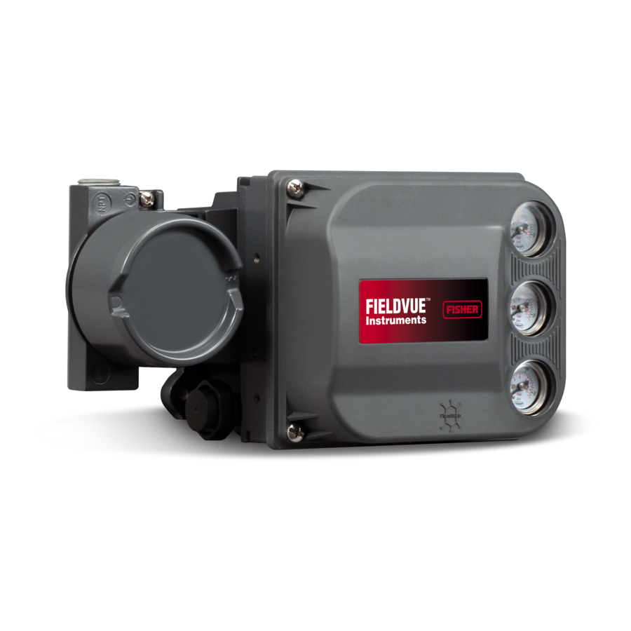
DVC6200 Digital Valve
HC, AD, PD, ODV
09
1 & 2
2
2, 3, 4, 5 & 6
1, 2, 3, 4 & 5
. . . . . . . . . . . . . . . . .
. . . . . . . . . . . . . . . . . . . . .
. . . . . . . . . . . . . . . .
. . . . . . . . . . . . . .
. . . . . . . . . . . . . . . . . .
. . . .
. . . . . . . . . . . . . . . . .
. . . . . . . . . . . . . . .
. . . . . . . . . . . . . . . . . . . . . . .
. . . . . . . . . . . . . . . . . . . .
3
3
3
W9713
3
3
5
5
8
9
9
9
9
11
12
12
13
15
15
. . . . . . . . . . . . . . . . . . . . . . . . . . . . . . . . . . . .
15
16
16
16
16
16
. . . . . . . . . . . . . . . . . . . . . . . . . . . . . . . . . . .
17
17
17
17
18
18
DVC6200 Digital Valve Controller
. . . . . . . . . . . . . . . . . . . . . .
. . . . . . . . . . . . . . . . . . .
. . . . . . . . . . . . . . . . . . . . . . .
. . . . . . . . . . . . . . . .
. . . . . . . . . . . . . . . . . . . . . . . .
. . . . . . . . . . . . . . . . . . . . . . . .
. . . . . . . . . . . . . . . . . . . . . . . . . .
. . . . . . . . . . . . . . . . . . . . . . . .
. . . . . . . . . . . . . . . . . . . . . .
. . . . . . . . . . . . . . . . . . . . . . . . . . .
. . . . . . . . . . . . . . . . . . . . . . . .
. . . . . . . . . . . . . . . . . . . . . . . . . .
. . . . . . . . . . . . . . . . . . . . . . . . . .
. . . . . . . . . . . . . . . . . . . .
. . . . . . . . . . . . . .
. . . . . . . . . . . . . . . . . . . . .
. . . . . . . . . . . . . . . . . . . . . . . . . . . . . . . . .
. . . . . . . . . . . . . . . . . . . .
February 2017
18
18
19
19
20
20
21
21
23
24
24
27
. . . . . . . . . .
27
28
30
33
. . . . . . . . . . . .
33
33
34
34
35
36
Advertisement
Table of Contents
Troubleshooting

Related Manuals for Fisher FIELDVUE DVC6200


Summary of Contents for Fisher FIELDVUE DVC6200
-
Page 1: Table Of Contents
Instruction Manual DVC6200 Digital Valve Controller D103605X012 February 2017 ™ ™ Fisher FIELDVUE DVC6200 Digital Valve Controller This manual applies to Instrument Level HC, AD, PD, ODV Device Type Device Revision 1 & 2 Hardware Revision Firmware Revision 2, 3, 4, 5 & 6 DD Revision 1, 2, 3, 4 &... - Page 2 Instruction Manual DVC6200 Digital Valve Controller February 2017 D103605X012 Contents (continued) Removing the Module Base ....Replacing the Module Base ....Section 4 Calibration .
-
Page 3: Section 1 Introduction
This instruction manual describes using the 475 Field Communicator to set up and calibrate the instrument. You can also use Fisher ValveLink software or ValveLink Mobile software to setup, calibrate, and diagnose the valve and instrument. For information on using ValveLink software with the instrument refer to ValveLink software help or documentation. - Page 4 Lead/Lag Set Point Filter 1. Refer to brochure part # D351146X012 for information on Fisher optimized digital valves for compressor antisurge applications. 2. HC = HART Communicating ; AD = Advanced Diagnostics ; PD = Performance Diagnostics ; ODV = Optimized Digital Valve.
-
Page 5: Specifications
D Using FIELDVUE Instruments with the Smart Wireless THUMt Adapter and a HART Interface Module (HIM) (D103469X012) D Audio Monitor for HART Communications (D103265X012) D HART Field Device Specification - Supplement to Fisher FIELDVUE DVC6200 Digital Valve Controller (D103639X012) D Using the HART Tri‐Loop HART‐to‐Analog Signal Converter with FIELDVUE Digital Valve Controllers (D103267X012) D Implementation of Lock‐in‐Last Strategy (D103261X012) D Fisher HF340 Filter Instruction Manual (D102796X012) - Page 6 Maximum particle density size: Class 7 DVC6200 digital valve controller or DVC6215 Oil content: Class 3 feedback unit: J Integral mounting to the Fisher GX Pressure Dew Point: Class 3 or at least 10 K less than Control Valve and Actuator System J Window the lowest ambient temperature expected mounting to Fisher rotary actuators J Sliding‐stem...
- Page 7 Instruction Manual Introduction D103605X012 February 2017 Table 1‐2. Specifications (continued) Lightning and Surge Protection—The degree of TIIS— Technology Institution of Industrial Safety immunity to lightning is specified as Surge immunity (Japan) in table 1‐3. For additional surge protection Contact your Emerson Automation Solutions sales commercially available transient protection devices office...
-
Page 8: Educational Services
Table 1‐2. Specifications (continued) Options (continued) Declaration of SEP Integral Switch Fisher Controls International LLC declares this One isolated switch, configurable throughout the product to be in compliance with Article 4 paragraph calibrated travel range or actuated from a device alert 3 of the PED Directive 2014/68/EU. -
Page 9: Section 2 Wiring Practices
Instruction Manual Wiring Practices D103605X012 February 2017 Section 2 Wiring Practices22 Control System Requirements There are several parameters that should be checked to ensure the control system is compatible with the DVC6200 digital valve controller. HART Filter Depending on the control system you are using, a HART filter may be needed to allow HART communication. The HART filter is a passive device that is inserted in field wiring from the HART loop. - Page 10 Instruction Manual Wiring Practices February 2017 D103605X012 As shown in figure 2‐2, the voltage available at the instrument depends upon: D the control system compliance voltage D if a filter, wireless THUM adapter, or intrinsic safety barrier is used, and D the wire type and length. The control system compliance voltage is the maximum voltage at the control system output terminals at which the control system can produce maximum loop current.
-
Page 11: Compliance Voltage
Instruction Manual Wiring Practices D103605X012 February 2017 Table 2‐1. Cable Characteristics Capacitance Capacitance Resistance Resistance Cable Type pF/Ft pF/m Ohms/ft Ohms/m BS5308/1, 0.5 sq mm 61.0 0.022 0.074 BS5308/1, 1.0 sq mm 61.0 0.012 0.037 BS5308/1, 1.5 sq mm 61.0 0.008 0.025 BS5308/2, 0.5 sq mm... -
Page 12: Auxiliary Terminal Wiring Length Guidelines
Instruction Manual Wiring Practices February 2017 D103605X012 Auxiliary Terminal Wiring Length Guidelines The Auxiliary Input Terminals of a DVC6200 with instrument level ODV can be used with a locally‐mounted switch for initiating a partial stroke test. Some applications require that the switch be installed remotely from the DVC6200. The length for wiring connected to the Auxiliary Input Terminals is limited by capacitance. -
Page 13: Installation In Conjunction With A Rosemountt 333 Hart Tri-Loopt Hart-To-Analog Signal Converter
Instruction Manual Wiring Practices D103605X012 February 2017 The following example shows how to calculate the cable length for a Foxboro I/A control system (1988) with a C master of 50, 000 pF and a Belden 9501 cable with characteristic capacitance of 50pF/ft. Length(ft) = [160,000 - 50,000pF] [50pF/ft] Length = 2200 ft. - Page 14 Instruction Manual Wiring Practices February 2017 D103605X012 Commissioning the Digital Valve Controller for use with the HART Tri‐Loop Signal Converter To prepare the digital valve controller for use with a 333 HART Tri‐Loop, you must configure the digital valve controller to burst mode, and select Burst Command 3.
-
Page 15: Section 3 Configuration
Instruction Manual Configuration D103605X012 February 2017 Section 3 Configuration Guided Setup Field Communicator Configure > Guided Setup (2‐1) To quickly setup the instrument, the following procedures will guide you through the process. D Device Setup—This procedure is used to configure actuator and valve information, calibrate the valve assembly, and assign the tuning set for the valve assembly. -
Page 16: Mode And Protection
Instruction Manual Configuration February 2017 D103605X012 Table 3‐1. Default Detailed Setup Parameters (continued) Setup Parameter Default Setting Travel Deviation Alert Enable Travel Deviation Alert Point Travel Deviation Time 9.99 sec Pressure Deviation Alert Enable Deviation & Other Alerts Pressure Deviation Alert Point 5 psi Pressure Deviation Alert Time 5.0 sec... -
Page 17: Serial Numbers
Instruction Manual Configuration D103605X012 February 2017 D Description—Enter a description for the application with up to 16 characters. The description provides a longer user‐defined electronic label to assist with more specific instrument identification than is available with the HART tag. D Message—Enter any message with up to 32 characters. Message provides the most specific user‐defined means for identifying individual instruments in multi‐instrument environments. -
Page 18: Spec Sheet
Instruction Manual Configuration February 2017 D103605X012 D Input Range Lo—Permits setting the Input Range Low value. Input Range Low should correspond to Travel Range Low, if the Zero Power Condition is configured as closed. If the Zero Power Condition is configured as open, Input Range Low corresponds to Travel Range High. -
Page 19: Cutoffs And Limits
Instruction Manual Configuration D103605X012 February 2017 D Fallback-Sensor/Tvl Deviation—The instrument will fallback to pressure control if a travel sensor failure is detected, or if the Tvl Dev Press Fallback setting is exceeded for more than the Tvl Dev Press Fallback Time. Note Travel / Pressure Select must be set to Travel for double‐acting actuators Cutoffs and Limits... -
Page 20: Pressure Control
Instruction Manual Configuration February 2017 D103605X012 D EPPC Set Point—Used in conjunction with End Point Pressure Control, End Point Pressure Control Set Point allows the user to select a pressure to be delivered by the instrument at the travel extreme. For a fail‐closed valve, this pressure must be sufficient to maintain the fully open position. -
Page 21: Control Mode
Instruction Manual Configuration D103605X012 February 2017 Control Mode D Control Mode—This displays the current control mode of the instrument. This will show Analog if the instrument is in PointtoPoint mode and is using a 420 mA signal for its power and set point. This will show Digital if the instrument is in Multidrop mode and is using 24 VDC for power and a digital set point for control. - Page 22 Instruction Manual Configuration February 2017 D103605X012 Figure 3‐2. Travel Target Versus Ranged Set Point, for Various Input Characteristics (Zero Power Condition = Closed) Ranged Set Point, % Ranged Set Point, % Input Characteristic = Linear Input Characteristic = Equal Percentage Ranged Set Point, % Input Characteristic = Quick Opening A6535‐1...
-
Page 23: Dynamic Response
Instruction Manual Configuration D103605X012 February 2017 Dynamic Response D SP Rate Open—Maximum rate (% of valve travel per second) at which the digital valve controller will move to the open position regardless of the rate of input current change. A value of 0 will deactivate this feature and allow the valve to stroke open as fast as possible. -
Page 24: Tuning
Stabilize/Optimize or Performance Tuner may be used to achieve the desired results more rapidly than manual Expert tuning. Table 3‐4 provides tuning set selection guidelines for Fisher and Baumann actuators. These tuning sets are only recommended starting points. After you finish setting up and calibrating the instrument, you may have to select either... - Page 25 (Window‐mount) 60, 70 Depends upon pneumatic connections. See 1061 Piston Dbl w/o Spring description for Travel Sensor Motion Fisher 68, 80, 100, 130 Mounting Style Travel Sensor Motion Away from the top of the instrument Towards the top of the...
- Page 26 The Performance Tuner is used to determine digital valve controller tuning. It can be used with digital valve controllers mounted on most sliding‐stem and rotary actuators, including Fisher and other manufacturers' products. Moreover, because the performance tuner can detect internal instabilities before they become apparent in the travel response, it can generally optimize tuning more effectively than manual tuning.
-
Page 27: Pressure Tuning
Instruction Manual Configuration D103605X012 February 2017 Pressure Tuning D Pressure Tuning Set There are twelve Pressure Tuning Sets to choose from. Each tuning set provides a preselected value for the digital valve controller gain settings. Tuning set C provides the slowest response and M provides the fastest response. Tuning set B is appropriate for controlling a pneumatic positioner. -
Page 28: Valve And Actuator
Instruction Manual Configuration February 2017 D103605X012 is configurable from 0% to 2%, corresponding to a symmetric window from 0% to +/-2% around the Primary Setpoint. Default value is 0.25%. D Integrator Limit—The Integrator Limit provides an upper limit to the integrator output. The high limit is configurable from 0 to 100% of the I/P drive signal. - Page 29 Instruction Manual Configuration D103605X012 February 2017 Zero Power Condition—The position of the valve (open or closed) when the electrical power to the instrument is removed. Zero Power Condition (ZPC) is determined by relay type, as shown in figure 3‐3. Figure 3‐3. Zero Power Condition Relay Type Loss of Electrical Power Single‐Acting Direct (Relay A or C)
-
Page 30: Partial Stroke Test
Instruction Manual Configuration February 2017 D103605X012 Partial Stroke Test (PST) (Instrument Level ODV only) Field Communicator Configure > Manual Setup > Partial Stroke (2-2-6) Note Partial Stroke is only available for instrument level ODV. Partial Stroke Test (PST) D PST Pressure Limit— This defines the actuator pressure at which a partial stroke test will abort. This prevents the DVC6200 from exhausting (or building) excessive pressure to the actuator in an attempt to move a stuck valve. - Page 31 Instruction Manual Configuration D103605X012 February 2017 Table 3‐7. Values for Disabling Partial Stroke Pressure Limit Actuator Type Relay Type Zero Power Condition Partial Stroke Start Point Partial Stroke Pressure Limit (Disabled) Open Closed Closed Psupply A or C Open Psupply Open Closed Single Acting...
- Page 32 Instruction Manual Configuration February 2017 D103605X012 PST Enable—Yes or No. This enables or disables the Partial Stroke Test. PST Start Point—Valve Open or Valve Closed. This defines the travel stop that the valve needs to be at before a partial stroke test can be initiated.
-
Page 33: Outputs
Instruction Manual Configuration D103605X012 February 2017 Outputs Field Communicator Configure > Manual Setup > Outputs (2-2-6) HC, AD, PD or (2-2-7) ODV Output Terminal Configuration Note These menu items are only available on units that have the optional 420 mA position transmitter or switch hardware installed. D Output Terminal Enable—If using the optional output terminal for a Position Transmitter or Switch output, this must be Enabled. -
Page 34: Hart Variable Assignments
Instruction Manual Configuration February 2017 D103605X012 HART Variable Assignments Instrument variables can be reported via four different HART variable assignments. The Primary Variable is always configured as Analog Input. However, the remaining three variables have additional options as listed below. Primary Variable (PV) Analog Input Secondary Variable (SV) -
Page 35: Alert Setup
Instruction Manual Configuration D103605X012 February 2017 Alert Setup Field Communicator Configure > Alert Setup (2‐3) An alert is a notification that the instrument has detected a problem. A shutdown is an action that the instrument takes to drive the air output to the Zero Power Condition as per figure 3‐3. Some alerts can be configured to shutdown the instrument. -
Page 36: Change To Hart 5 / Hart 7
Instruction Manual Configuration February 2017 D103605X012 Change to HART 5 / Change to HART 7 Field Communicator Service Tool > Maintenance > Change to HART 5 / Change to HART 7 (3-5-3) HC or (3-5-4) AD, PD or (3-5-5) ODV Note This procedure must never be done while the valve is in service and controlling the process. -
Page 37: Section 4 Calibration
Instruction Manual Calibration D103605X012 February 2017 Section 4 Calibration Calibration Overview When a DVC6200 digital valve controller is ordered as part of a control valve assembly, the factory mounts the digital valve controller on the actuator and connects the necessary tubing, then sets up and calibrates the controller. For digital valve controllers that are ordered separately, recalibration of the analog input or pressure sensors generally is unnecessary. -
Page 38: Travel Calibration
Instruction Manual Calibration February 2017 D103605X012 Travel Calibration If a double‐acting relay is used, you will be prompted to run the relay adjustment when auto or manual calibration is selected. Select Yes to adjust the relay, select No to proceed with calibration. For additional information, refer to Relay Adjustment on page 43. -
Page 39: Manual Calibration
Instruction Manual Calibration D103605X012 February 2017 Manual Calibration Two procedures are available to manually calibrate travel: D Analog Adjust— This procedure is used when you can manually change the 4-20 mA current source to move the valve. D Digital Adjust— This procedure is used when the 4-20 mA current source cannot be manually changed. Analog Calibration Adjust Connect a variable current source to the instrument LOOP + and LOOP - terminals. -
Page 40: Pushbutton Calibration
Instruction Manual Calibration February 2017 D103605X012 2. From the adjustment menu, select the direction and size of change required to set the travel at 0%. Selecting large, medium, and small adjustments causes changes of approximately 10.0%, 1.0%, and 0.1%, respectively. If another adjustment is required, repeat step 2. -
Page 41: Sensor Calibration
Instruction Manual Calibration D103605X012 February 2017 Sensor Calibration Pressure Sensors Note The pressure sensor is calibrated at the factory and should not require calibration. Output Pressure Sensor To calibrate the output pressure sensor, connect an external reference gauge to the output being calibrated. The gauge should be capable of measuring maximum instrument supply pressure. -
Page 42: Analog Input Calibration
Instruction Manual Calibration February 2017 D103605X012 Supply Pressure Sensor Note Supply Pressure Sensor Calibration is not available for instrument level HC. To calibrate the supply pressure sensor, connect an external reference gauge to the output side of the supply regulator. The gauge should be capable of measuring maximum instrument supply pressure. Follow the prompts on the Field Communicator display to calibrate the instrument's supply pressure sensor. -
Page 43: Relay Adjustment
Instruction Manual Calibration D103605X012 February 2017 Press OK when you have read this message. 3. The value of the Analog Input appears on the display. Press OK to display the adjustment menu. 4. From the adjustment menu, select the direction and size of adjustment to the displayed value. Selecting large, medium, and small adjustments causes changes of approximately 0.4 mA, 0.04 mA, and 0.004 mA, respectively. -
Page 44: Single-Acting Relays
Instruction Manual Calibration February 2017 D103605X012 Figure 4‐1. Relay A Adjustment (Shroud Removed for Clarity) FOR SINGLE‐ACTING DIRECT RELAYS: ROTATE ADJUSTMENT DISC IN THIS DIRECTION UNTIL IT CONTACTS THE BEAM FOR DOUBLE‐ACTING RELAYS: ROTATE ADJUSTMENT DISC IN THIS DIRECTION TO DECREASE OUTPUT PRESSURE ADJUSTMENT DISC FOR DOUBLE‐ACTING RELAYS:... -
Page 45: Pst Calibration
Instruction Manual Calibration D103605X012 February 2017 PST Calibration (ODV Instrument Level only) This procedure permits you to run the Partial Stroke Calibration, which enables the Partial Stroke Test. It establishes values for Partial Stroke Pressure Limit, Pressure Set Point and Pressure Saturation Time for End Point Pressure Control, Travel Deviation Alert Point and Travel Deviation Time. - Page 46 Instruction Manual Calibration February 2017 D103605X012...
-
Page 47: Section 5 Device Information, Diagnostics, And Alerts
Instruction Manual Device Information, Diagnostics, and Alerts D103605X012 February 2017 Section 5 Device Information, Diagnostics, and Alerts55 Overview Field Communicator Overview (1) Status & Primary Purpose Variables The overview section provides basic information about the current state of the instrument and gives you access to the current values of: D Alert Status D Communication Status... -
Page 48: Service Tools
Instruction Manual Device Information, Diagnostics, and Alerts February 2017 D103605X012 Service Tools Field Communicator Service Tools (3) Device Status Instrument alerts, when enabled, detect many operational and performance issues that may be of interest. If there are no alerts currently active, this display will be empty. Alert Record The DVC6200 will store 20 alerts. -
Page 49: Pressure
Instruction Manual Device Information, Diagnostics, and Alerts D103605X012 February 2017 D Variable Out of Range—This alert is active if one or more of the measured analog sensor readings (loop current, pressure, temperature, or travel) is saturated or reading out of its configured range. The condition may be due to improper configuration or physical setup and not be due to a sensor malfunction. -
Page 50: Travel
Instruction Manual Device Information, Diagnostics, and Alerts February 2017 D103605X012 Travel Note The Travel Alert Deadband applies to the Travel Deviation Alert as well as the Travel Alert Hi, Lo, Hi Hi, and Lo Lo. D Travel Deviation Alert—If the difference between the Travel Target and the Travel exceeds the Travel Deviation Alert Point for more than the Travel Deviation Time, the Travel Deviation Alert is active. -
Page 51: Travel History
Instruction Manual Device Information, Diagnostics, and Alerts D103605X012 February 2017 Travel History D Cycle Count High Alert—This alert is active if the Cycle Counter exceeds the Cycle Count Alert Point. The Cycle Count records the number of times the travel changes direction when it is outside of the deadband. To clear the alert, set the Cycle Counter to a value less than the alert point. -
Page 52: Status
Instruction Manual Device Information, Diagnostics, and Alerts February 2017 D103605X012 Status D Calibration in Progress Alert—This alert is active when calibration is in progress. D AutoCal in Progress Alert—This alert is active when auto calibration is in progress. D Diagnostic in Progress Alert—This alert is active when a diagnostic test is in progress. D Diagnostic Data Available Alert—This alert is active when diagnostic data has been collected and is being stored in the instrument. -
Page 53: Variables
Instruction Manual Device Information, Diagnostics, and Alerts D103605X012 February 2017 When enabled, a partial stroke test may be initiated by the device (as a scheduled, auto partial stroke test), a remote pushbutton located in the field or at the valve, a Field Communicator, or ValveLink software. D Automatic (Scheduled) The Auto Partial Stroke Test allows the partial stroke test to be scheduled by the DVC6200. - Page 54 Instruction Manual Device Information, Diagnostics, and Alerts February 2017 D103605X012 D Actuator Pressure(s) D Travel/Pressure Control Configuration (also provides a procedure to modify) D Control Mode (also provides a procedure to modify) D Instrument Temperature D Travel Counts (this is the raw travel sensor reading used for advanced adjustments) D Maximum Recorded Temperature D Minimum Recorded Temperature D Number of Power Ups...
-
Page 55: Section 6 Maintenance And Troubleshooting
Instruction Manual Maintenance and Troubleshooting D103605X012 February 2017 Section 6 Maintenance and Troubleshooting66 The DVC6200 digital valve controller enclosure is rated Type 4X and IP66, therefore periodic cleaning of internal components is not required. If the DVC6200 is installed in an area where the exterior surfaces tend to get heavily coated or layered with industrial or atmospheric contaminants, however, it is recommended that the vent (key 52) be periodically inspected to ensure it is fully open. -
Page 56: Replacing The Magnetic Feedback Assembly
Instruction Manual Maintenance and Troubleshooting February 2017 D103605X012 from fire or explosion if natural gas is used as the supply medium and appropriate preventive measures are not taken. Preventive measures may include, but are not limited to, one or more of the following: ensuring adequate ventilation and the removal of any ignition sources. -
Page 57: Component Replacement
Instruction Manual Maintenance and Troubleshooting D103605X012 February 2017 Component Replacement When replacing any of the components of the DVC6200, the maintenance should be performed in an instrument shop whenever possible. Make sure that the electrical wiring and pneumatic tubing is disconnected prior to disassembling the instrument. -
Page 58: Replacing The Module Base
Instruction Manual Maintenance and Troubleshooting February 2017 D103605X012 Replacing the Module Base Refer to figure 7‐2 or 7‐4 for key number locations. CAUTION To avoid affecting performance of the instrument, take care not to damage the module base seal or guide surface. Do not bump or damage the bare connector pins on the PWB assembly. -
Page 59: I/P Converter
Instruction Manual Maintenance and Troubleshooting D103605X012 February 2017 I/P Converter Refer to figure 7‐2 or 7‐4 for key number locations. The I/P converter (key 41) is located on the front of the module base. Note After I/P converter submodule replacement, calibrate the digital valve controller to maintain accuracy specifications. Replacing the I/P Filter A screen in the supply port beneath the I/P converter serves as a secondary filter for the supply medium. - Page 60 Instruction Manual Maintenance and Troubleshooting February 2017 D103605X012 4. Ensure that the O‐ring (key 39) and screen (key 231) stay in the module base and do not come out with the I/P converter (key 41). Replacing the I/P Converter 1. Refer to figure 6‐2. Inspect the condition of the O‐ring (key 39) and screen (key 231) in the module base (key 2). Replace them, if necessary.
-
Page 61: Printed Wiring Board (Pwb) Assembly
Instruction Manual Maintenance and Troubleshooting D103605X012 February 2017 Printed Wiring Board (PWB) Assembly Refer to figure 7‐2 or 7‐4 for key number locations. The PWB assembly (key 50) is located on the back of the module base assembly (key 2). Note If the PWB assembly submodule is replaced, calibrate and configure the digital valve controller to maintain accuracy specifications. - Page 62 Instruction Manual Maintenance and Troubleshooting February 2017 D103605X012 Figure 6‐4. Printed Wiring Board (PWB) Connections and Settings TRAVEL SENSOR CONNECTOR TERMINAL BOX CONNECTOR OPERATIONAL MODE SELECTION X0463 TRAVEL SENSOR TRANSMITTER / SWITCH CONNECTOR SELECTION TERMINAL BOX CONNECTOR OPERATIONAL MODE SELECTION X0432 Note For the digital valve controller to operate with a 4 to 20 mA control signal, be sure the DIP switch is in the point‐to‐point loop...
-
Page 63: Pneumatic Relay
Instruction Manual Maintenance and Troubleshooting D103605X012 February 2017 Pneumatic Relay Refer to figure 7‐2 or 7‐4 for key number locations. The pneumatic relay (key 24) is located on the front of the module base. Note After relay submodule replacement, calibrate the digital valve controller to maintain accuracy specifications. Removing the Pneumatic Relay 1. -
Page 64: Terminal Box
Instruction Manual Maintenance and Troubleshooting February 2017 D103605X012 Perform the following procedure to replace the gauges, tire valves, or pipe plugs. Refer to figure 7‐2 and 7‐3 for key number locations. 1. Remove the front cover (key 43). 2. Remove the gauge, pipe plug, or tire valve as follows: For gauges (key 47), the flats are on the gauge case. -
Page 65: Replacing The Terminal Box
Instruction Manual Maintenance and Troubleshooting D103605X012 February 2017 3. Separate the module base from the housing by performing the Removing the Module Base procedure. 4. Disconnect the terminal box wiring connector from the PWB assembly (key 50). 5. Remove the screw (key 72). Pull the terminal box assembly straight out of the housing. Replacing the Terminal Box Note Inspect all O‐rings for wear and replace as necessary. -
Page 66: Restart Processor
Instruction Manual Maintenance and Troubleshooting February 2017 D103605X012 5. Adjust the resistance of the 1 kilohm potentiometer until the voltage read on the voltmeter is 10.0 volts. 6. Record the current shown on the milliammeter. 7. If the current recorded in step 6 is the same as that recorded in step 4 (± 0.08 mA), the voltage available is adequate. - Page 67 Instruction Manual Maintenance and Troubleshooting D103605X012 February 2017 Table 6‐3. Instrument Troubleshooting Symptom Possible Cause Action 2. Instrument will not 2j. PWB failure. 2j. Use a 4-20 mA current source to apply power to the communicate. instrument. Terminal voltage across the LOOP+ and LOOP- terminals should be 8.0 to 9.5 VDC.
-
Page 68: Dvc6200 Technical Support Checklist
Instruction Manual Maintenance and Troubleshooting February 2017 D103605X012 DVC6200 Technical Support Checklist Have the following information available prior to contacting your Emerson Automation Solutions sales office support. 1. Instrument serial number as read from nameplate ________________________________________________ 2. Is the digital valve controller responding to the control signal? Yes _________ No _________ If not, describe ___________________________________________________________________________ 3. -
Page 69: Section 7 Parts
Use only genuine Fisher replacement parts. Components that are not supplied by Emerson Automation Solutions should not, under any circumstances, be used in any Fisher instrument. Use of components not supplied by Emerson Automation Solutions may void your warranty, might adversely affect the performance of the instrument, and could cause personal injury and property damage. - Page 70 Instruction Manual Parts D103605X012 February 2017 Description Part Number Figure 7‐1. Terminal Box Note The Remote Mount Feedback Unit kit is not orderable by part number due to nameplate/approval requirements. Contact your Emerson Automation Solutions sales office for information on ordering this kit. 9 Remote Mount Feedback Unit Kit (see figure 7‐5) [remote housing assembly (key25);...
-
Page 71: Parts List
Instruction Manual Parts D103605X012 February 2017 Parts List Description Part Number 63 Lithium grease (not furnished with the instrument) 64 Pipe thread sealant (not furnished with the instrument) 65 Lubricant, silicone sealant (not furnished with the instrument) Note Retaining Ring (3 req'd) Parts with footnote numbers shown are available in parts kits;... -
Page 72: Terminal Box
Instruction Manual Parts February 2017 D103605X012 Description Part Number Description Part Number 24* Relay Assembly, (includes shroud, relay seal, mounting screws) Pressure Gauges, Pipe Plugs, or (continued) Extreme Temperature option (fluorosilicone elastomers) Tire Valve Assemblies Standard Bleed (see figure 7‐3) Single‐acting direct (relay C) 38B5786X142 Double‐acting (relay A) - Page 73 Instruction Manual Parts D103605X012 February 2017 Figure 7‐2. FIELDVUE DVC6200 Digital Valve Controller Housing Assembly HOUSING B—BACK VIEW HOUSING A—BACK VIEW (USED FOR ALL (USED FOR GX ACTUATOR) ACTUATORS EXCEPT GX) DOUBLE‐ACTING DIRECT‐ACTING REVERSE‐ACTING APPLY LUBRICANT, SEALANT, OR THREAD LOCK...
- Page 74 Instruction Manual Parts February 2017 D103605X012 Figure 7‐2. FIELDVUE DVC6200 Digital Valve Controller Housing Assembly (continued) SECTION C-C SCALE 2 : 1 SECTION A-A SECTION E-E SCALE 2 : 1 SECTION F-F SCALE 2 : 1 APPLY LUBRICANT, SEALANT, OR THREAD LOCK...
- Page 75 Instruction Manual Parts D103605X012 February 2017 Figure 7‐4. FIELDVUE DVC6205 Base Unit Housing Assembly SECTION B-B SECTION A-A SECTION H-H APPLY LUBRICANT, SEALANT, OR THREAD LOCK APPLY LUBRICANT ON ALL O-RINGS UNLESS OTHERWISE SPECIFIED GE40181...
- Page 76 Instruction Manual Parts February 2017 D103605X012 Figure 7‐4. FIELDVUE DVC6205 Base Unit Housing Assembly (continued) SECTION C-C SCALE 2 : 1 SECTION E-E SCALE 2 : 1 DOUBLE‐ACTING SHOWN DOUBLE‐ACTING DIRECT‐ACTING REVERSE‐ACTING APPLY LUBRICANT, SEALANT, OR THREAD LOCK APPLY LUBRICANT ON ALL O-RINGS UNLESS OTHERWISE SPECIFIED GE40181...
- Page 77 Instruction Manual Parts D103605X012 February 2017 Figure 7‐4. FIELDVUE DVC6205 Base Unit Housing Assembly (continued) PIPE MOUNTING WALL MOUNTING APPLY LUBRICANT, SEALANT, OR THREAD LOCK APPLY LUBRICANT ON ALL O-RINGS UNLESS OTHERWISE SPECIFIED GE40181...
- Page 78 Instruction Manual Parts February 2017 D103605X012 Figure 7‐5. FIELDVUE DVC6215 Remote Feedback Assembly SECTION A-A PARTS NOT SHOWN: 158 APPLY LUBRICANT/SEALANT GE46670-B HOUSING A (USED FOR GX ACTUATOR) SECTION A-A PARTS NOT SHOWN: 158 APPLY LUBRICANT/SEALANT GE40178-B HOUSING B (USED FOR ALL ACTUATORS EXCEPT GX)
-
Page 79: Appendix A Principle Of Operation
Instruction Manual Principle of Operation D103605X012 February 2017 Appendix A Principle of OperationAA−A HART Communication The HART (Highway Addressable Remote Transducer) protocol gives field devices the capability of communicating instrument and process data digitally. This digital communication occurs over the same two‐wire loop that provides the 4‐20 mA process control signal, without disrupting the process signal. - Page 80 Instruction Manual Principle of Operation February 2017 D103605X012 Figure A‐2. Typical FIELDVUE Instrument to Personal Computer Connections for ValveLink Software CONTROL SYSTEM HART MODEM FIELD TERM. E1362 DVC6200 digital valve controllers are loop‐powered instruments that provide a control valve position proportional to an input signal from the control room.
- Page 81 Instruction Manual Principle of Operation D103605X012 February 2017 Figure A‐3. FIELDVUE DVC6200 Digital Valve Controller Block Diagram INPUT SIGNAL 4-20 mA HART VALVE TRAVEL FEEDBACK PRINTED WIRING BOARD DRIVE SIGNAL TERMINAL BOX OUTPUT A AUXILIARY TERMINALS PNEUMATIC CONVERTER RELAY SUPPLY PRESSURE...
- Page 82 Instruction Manual Principle of Operation February 2017 D103605X012...
-
Page 83: Appendix B Field Communicator Menu Tree
Instruction Manual Field Communicator Menu Trees D103605X012 February 2017 Appendix B Field Communicator Menu Trees This section contains the Field Communicator menu trees for instrument level HC, AD, PD, and ODV. It also contains an alphabetized function/variable list to help locate the function/variable on the appropriate menu tree. All Fast Key Sequences referenced in the menu trees assume the Online menu (see figure B-2) as the starting point. - Page 84 Instruction Manual Field Communicator Menu Trees February 2017 D103605X012 Function/Variable See Figure Function/Variable See Figure Lo Limit/Cutoff Point B-6, B-8 SP Rate Open Lo Limit/Cutoff Select B-6, B-8 Spring Rate Manual Calibration Spring Rate Units Manufacturer (Device) Stabilize/Optimize B-4, B-7, B-10 Maximum Recorded Temperature B-10 Stem Diameter...
- Page 85 Instruction Manual Field Communicator Menu Trees D103605X012 February 2017 Figure B-1. Hot Key Figure B-2. Online HART Application Hot Key 1 Offline Online 2 Online 1 Instrument Mode 3 Utility 2 Change Instrument Mode 1 Overview 4 HART Diagnostics 3 Write Protection 2 Configure 4 Change Write Protection 3 Service Tools Figure B-3.
- Page 86 Instruction Manual Field Communicator Menu Trees February 2017 D103605X012 Figure B-5. Manual Setup > Mode Protection (2-2-1) and Manual Setup > Instrument (2-2-2) 2-2-1 Mode and Protection 2-2-2-1 Identification 1 Instrument Mode 2 Change Instrument Mode 1 HART Tag 3 Write Protection 2 HART Long Tag 4 Change Write Protection Manual Setup 3 Description...
- Page 87 Instruction Manual Field Communicator Menu Trees D103605X012 February 2017 Figure B-6. Manual Setup > Travel/Pressure Control (2-2-3) 2-2-3 Travel/Pressure Control HC, AD, PD 1 Travel/Pressure Select 2-2-3-2 2 Cutoffs and Limits Cutoffs and Limits 3 Pressure Control 1 Hi Limit/Cutoff Select 4 Pressure Fallback 2 Hi Limit/Cutoff Point 5 Control Mode 3 Lo Limit/Cutoff Select 6 Characterization...
- Page 88 Instruction Manual Field Communicator Menu Trees February 2017 D103605X012 Figure B-7. Manual Setup > Tuning (2-2-4) through Manual Setup > Outputs (2-2-7) 2-2-4-1 Travel Tuning 2-2-4 Tuning 1 Travel Tuning Set 2 Proportional Gain 1 Travel Tuning 3 Velocity Gain 2 Pressure Tuning 4 MLFB Gain 3 Travel/Pressure Integral Settings 5 Integral Enable Manual Setup...
- Page 89 Instruction Manual Field Communicator Menu Trees D103605X012 February 2017 Figure B-8. Alert Setup (2-3) 2-3-1 Electronics 1 Drive Signal Alert Enable 2-3-2-2 (HC) 2-3-3-2 (AD, PD, ODV) 2-3-2 (AD, PD, ODV) Travel Deviation Supply Pressure Lo Alert 1 Travel Deviation 1 Supply Pressure Lo Alert Enable 2 Travel Deviation Alert Enable 2 Supply Pressure Lo Alert Point Alert Setup...
- Page 90 Instruction Manual Field Communicator Menu Trees February 2017 D103605X012 Figure B-9. Calibration (2-4) HART 5 2-4-1 Travel Calibration 1 Auto Calibration 2 Last AutoCal Status 3 Manual Calibration 4 Calibration Record Calibration HART 7 2-4-1 HART 7 1 Travel Calibration Travel Calibration 2 Relay Adjust 1 Auto Calibration 3 Sensor Calibration 2 Last AutoCal Status 4 PST Calibration...
-
Page 91: Glossary
Instruction Manual Glossary D103605X012 February 2017 Glossary Alert Point Control Loop An adjustable value that, when exceeded, An arrangement of physical and electronic activates an alert. components for process control. The electronic components of the loop continuously measure one or more aspects of the process, then alter Algorithm those aspects as necessary to achieve a desired process condition. - Page 92 Hardware Revision The signal to the I/P converter from the printed wiring board. It is the percentage of the total Revision number of the Fisher instrument microprocessor effort needed to drive the valve hardware. The physical components of the fully open.
- Page 93 Instruction Manual Glossary D103605X012 February 2017 HART (acronym) Instrument Protection The acronym HART stands for Highway Determines if commands from a HART device can Addressable Remote Transducer. calibrate and/or configure certain parameters in the instrument. There are two types of instrument protection: HART Universal Revision Configuration and Calibration: Prohibits changing...
- Page 94 Instruction Manual Glossary February 2017 D103605X012 Minimum Closing Time Primary Master Minimum time, in seconds, for the travel to Masters are communicating devices. A primary decrease through the entire ranged travel. This master is a communicating device permanently rate is applied to any travel decrease. Valid entries wired to a field instrument.
- Page 95 Instruction Manual Glossary D103605X012 February 2017 Set Point Filter Time (Lag Time) Travel Accumulator Deadband The time constant, in seconds, for the first‐order Region around the travel reference point input filter. The default of 0 seconds will bypass established at the last increment of the the filter.
- Page 96 Instruction Manual Glossary February 2017 D103605X012 Travel Deviation Travel Sensor The difference between the analog input signal A device within the FIELDVUE instrument that (in percent of ranged input), the “target” travel, senses valve stem or shaft movement. The travel and the actual “ranged”...
-
Page 97: Index
Instruction Manual Index D103605X012 February 2017 Index Calibration in Progress Alert, 52 Certifications, Other China, NEPSI, 7 India, PESO CCOE, 7 Japan, TIIS, 7 Russia, Kazakhstan and Belarus, CUTR, 7 Actuator Compatibility, 7 South Korea, KGS, 7 Actuator Style, 28 Change Control Mode, 21 Alert Record Full Alert, 51 Change HART Universal Revision, 36... - Page 98 Instruction Manual Index February 2017 D103605X012 Pressure, 49 Filter Settings, Typical Lead/Lag, 23 Status, 52 Flash Integrity Failure, 48 Travel, 50 frequency shift keying (FSK), 79 Travel History, 51 Function, Output Terminal Configuration Diagnostic Data Available Alert, 52 Alert Switch, 33 Diagnostic in Progress Alert, 52 Limit Switch, 33 Transmitter, 33...
- Page 99 Instruction Manual Index D103605X012 February 2017 Input Range Lo, 18 Lloyds Register, Marine Type Approval, Other Classifications/Certifications, 7 Input Signal, 6 Lo Limit/Cutoff Point, 19 Installation, 3 Lo Limit/Cutoff Select, 19 Instrument Level, Capabilities, 4 Loop Current Validation Alert, 49 Instrument Mode, 16 Instrument Time, Edit, 18 Instrument Time is Approximate Alert, 49...
- Page 100 Instruction Manual Index February 2017 D103605X012 Pneumatic Relay maintenance, 63 removing, 63 Offline/Failed Alert, 48 replacing, 63 Options, 7, 8 Polling Address, 17 Output Circuit Communication Failure, 49 Position Transmitter, 33 Output Pressure Sensor, Calibration, 41 Pressure Control, 20 Pressure Range High, 20 Output Signal, 6 Pressure Range Lo, 20 Output Terminal Configuration, 33...
- Page 101 Instruction Manual Index D103605X012 February 2017 Restart Control Mode, 21 Switch Configuration, 33 Alert Switch Source, 33 Restart Processor, 66 Limit Switch Trip Point, 33 RShaft End Mount, Magnet Assembly, 28 Switch Closed, 33 RShaft Window #1, Magnet Assembly, 28 RShaft Window #2, Magnet Assembly, 28 Technical Support Checklist, 68 Temperature Limits, Operating Ambient, 6...
- Page 102 Instruction Manual Index February 2017 D103605X012 End Point Pressure Control, 19 Fallback Recovery, 20 Pressure Control, 20 Valve Serial Number, 17 Pressure Fallback, 20 Valve Style, 28 Travel/Pressure Select, 18 Tvl Dev Press Fallback, 20 ValveLink software, 4 Tvl Dev Press Fallback Time, 20 Variable Out of Range, 49 Travel/Pressure Select, 18 Variables, Status &...
- Page 103 Instruction Manual DVC6200 Digital Valve Controller D103605X012 February 2017...
- Page 104 Responsibility for proper selection, use, and maintenance of any product remains solely with the purchaser and end user. Fisher, FIELDVUE, ValveLink, PROVOX, Rosemount, Tri-Loop, DeltaV, RS3, and THUM are marks owned by one of the companies in the Emerson Automation Solutions business unit of Emerson Electric Co.