Sign In
Upload
Manuals
Brands
Daikin Manuals
Air Conditioner
FBQ60B7V1 x 2
Daikin FBQ60B7V1 x 2 Manuals
Manuals and User Guides for Daikin FBQ60B7V1 x 2. We have
7
Daikin FBQ60B7V1 x 2 manuals available for free PDF download: Service Manual, Operation Manual
Daikin FBQ60B7V1 x 2 Service Manual (502 pages)
SkyAir series Service Diagnosis
Brand:
Daikin
| Category:
Air Conditioner
| Size: 2.95 MB
Table of Contents
Table of Contents
2
1 List of Applicable Models
8
R-FU Series
8
R-GA Series
9
R-G Series
9
R-KU Series
10
R-LU Series
11
2 Symptom-Based Troubleshooting
36
2.1 Overview
36
Applicable Model
38
Supposed Causes
38
2.2 Equipment Does Not Operate
38
Troubleshooting
39
Indoor Unit Fan Operates, but Compressor Does Not Operate
40
Cooling / Heating Operation Starts but Stops Immediately
43
After Unit Shuts Down, It Cannot be Restarted for a While
45
Equipment Operates but Does Not Provide Cooling
48
Equipment Operates but Does Not Provide Heating
51
Equipment Discharges White Mist
54
Equipment Produces Loud Noise or Vibration
56
2.10 Equipment Discharges Dust
59
Remote Controller LCD Displays "88
60
3 Troubleshooting by Remote Controller
61
Procedure of Self-Diagnosis by Remote Controller
61
Wired Remote Controller
62
Hecking an Error or Warning
62
Wireless Remote Controller
63
Taking Corrective Action
63
3.2 Error Codes and Description
66
Outdoor Unit, System
69
Inverter Series
71
3.3 Detailed Error Codes
80
A0 Error of External Protection Device
86
Method of Error Detection
86
Error Decision Conditions
86
A1 Indoor Unit PCB Abnormality
88
A3 Drain Water Level System Abnormality
90
A6 Indoor Unit Fan Motor Abnormality
93
A6 Fan Motor (M1F) Lock, Overload
103
A7 Swing Flap Motor Abnormality / Lock
105
A8 Abnormal Power Supply Voltage
107
A9 Electronic Expansion Valve Coil (Y1E) Abnormality
109
AF Drain System Abnormality
112
AF Drain Level above Limit
114
AJ Capacity Setting Abnormality
115
Remote Controller Display
117
C1 Transmission Error (between Indoor Unit PCB and Fan PCB)
122
C1 Transmission Error (between Indoor Unit PCB and Adaptor PCB)
125
C4, C5, C9 Thermistor Abnormality
128
C6 Defective Combination (between Indoor Unit PCB and Fan PCB)
130
CC Humidity Sensor System Abnormality
132
CJ Remote Controller Thermistor Abnormality
135
E0 Actuation of Safety Device
137
E0 Activation of Outdoor Unit Protection Device
145
E1 Outdoor Unit PCB Abnormality
147
E3 High Pressure System Abnormality
150
E3 Abnormally High Pressure Level (HPS)
155
E3 High Pressure Abnormality (HPS)
157
E3 Actuation of High Pressure Switch
160
E4 Low Pressure System Abnormality
169
E4 Actuation of Pressure Sensor
171
E4 Actuation of Low Pressure Sensor
175
E4 Low Pressure System Abnormality
180
E5 Compressor Motor Lock
183
E6 Compressor Overcurrent
188
Approximate Input Current Value
190
E7 Outdoor Unit Fan Motor Abnormality
191
E9 Electronic Expansion Valve Abnormality
203
E9 Electronic Expansion Valve Coil Abnormality
207
F3 Discharge Pipe Temperature Abnormality
217
F3 Discharge Pipe Temperature Control
225
F6 Abnormal Heat Exchanging Temperature
227
F6 Refrigerant Overcharged
229
H3 High Pressure Switch Abnormality
231
H3 High Pressure Switch System Abnormality
236
H4 Low Pressure Sensor System Abnormality
238
H7 Outdoor Unit Fan Motor Signal Abnormality
242
H9, J3, J5, J6, J7, J8 Thermistor System Abnormality
244
H9 Outdoor Air Thermistor System Abnormality
246
J1 Pressure Sensor Abnormality
248
J2 Current Sensor System Abnormality
250
J3 Discharge Pipe Thermistor System Abnormality
252
J5 Suction Pipe Thermistor Abnormality
255
J6 Heat Exchanger Thermistor System Abnormality
257
J7 Liquid Pipe Thermistor Abnormality
259
J9 Subcooling Heat Exchanger Gas Pipe Thermistor Abnormality
261
JA High Pressure Sensor Abnormality
263
JC Suction Pipe Pressure Sensor Abnormality
266
L1 Outdoor Unit PCB Abnormality
268
L1 Outdoor Inverter PCB Abnormality
270
L1 Outdoor Unit PCB Abnormality
272
L4 Overcurrent of DC Output (Instantaneous)
275
L4 Radiation Fin Temperature Rise
277
Radiation Fin Temperature Detection Value
279
L5 Overcurrent of DC Output (Instantaneous)
285
L5 Momentary Overcurrent of Inverter Compressor
288
L5 Output Overcurrent Detection
291
L5 Inverter Compressor Abnormality
294
L5 Output Overcurrent Detection
297
(L8) Electronic Thermal Switch (Time Lag)
301
L8 Inverter Current Abnormality
304
L8 Inverter Compressor Overcurrent
307
L8 Electronic Thermal (Time Lag)
310
L9 Stall Prevention (Time Lag)
316
L9 Inverter Startup Error
318
LC Transmission Error between Inverter and Control PCB
324
LC Transmission Error (between Control PCB and Inverter PCB)
330
P1 Inverter Over-Ripple Protection
333
P1 Open Phase or Power Supply Voltage Imbalance
336
P4 Radiation Fin Thermistor Abnormality
338
P4 Radiation Fin Thermistor or Related Abnormality
342
PJ Defective Capacity Setting
343
PJ Error in Capacity Setting
345
PJ Field Setting Error after Replacing Main PCB or Defective Combination of PCB
346
PJ Defective Combination of Inverter and Fan Driver
348
PJ Defective Capacity Setting
350
U0 Refrigerant Shortage
354
U0 Low Pressure Drop Due to Refrigerant Shortage or Electronic Expansion Valve Failure
356
U0 Refrigerant Shortage
359
U1 Reverse Phase
365
U2 Insufficient Voltage
368
U2 Power Supply Voltage Abnormality
370
U2 Power Supply Insufficient or Instantaneous Failure
372
U2 Power Supply Voltage Abnormality
377
U3 Check Operation Is Not Executed
380
U4 or UF Transmission Error (between Indoor Unit and Outdoor Unit)
382
U4 Transmission Error between Indoor Unit and Outdoor Unit
388
U5 Transmission Error between Indoor Unit and Remote Controller
411
U7 Transmission Error between Outdoor Units
419
U8 Transmission Error between Main Remote Controller and Sub Remote Controller
422
U9 Transmission Error between Indoor and Outdoor Units in the same System
428
UA Defective Field Setting Switch
431
UA Improper Combination of Indoor and Outdoor Units, Indoor Units and Remote Controller
434
UA Field Setting Switch Abnormality
437
UA Field Setting Switch and Transmission Line Abnormality
440
UC Centralized Address Setting Error
444
UC Address Duplication of Centralized Controller
445
UE Transmission Error between Centralized Controller and Indoor Unit
446
UF Mis-Connection of Field Wiring
454
UF System Is Not Set yet
455
UF Transmission Error between Indoor and Outdoor Unit / Piping and Wiring Mismatch / Refrigerant Shortage
457
Outdoor Units
458
UF Transmission System Abnormality (between Indoor and Outdoor Units)
462
UH System Error, Refrigerant System Address Undefined
463
Check for Fan Motor Connector (Signal Line)
466
3.110 Check
466
Check for Fan Motor Connector (Power Supply Line)
467
Thermistor Resistance / Temperature Characteristics
468
Evaluation of Abnormal High Pressure
471
In Cooling Operation
471
In Heating Operation
472
Evaluation of Abnormal Low Pressure
473
Check for Power Transistor
475
Voltage Measuring Method
477
Pressure Sensor for Except RZQ(S)-B, RZQ-C7 and CMSQ
478
Pressure Sensor for RZQ(S)-B, RZQ-C7 and CMSQ
479
Electronic Expansion Valve Connector and Coil Resistance Criteria
480
Check for Factors Causing Wet Operation
481
Check for Excessive Refrigerant Charging
482
Check for Clogged Points
484
Check for Inadequate Refrigerant
485
Diagnosis of Inadequate Refrigerant
487
Fan Motor Pulse Check
489
Check for Causes of Rise in High Pressure
490
Check for Causes of Drop in Low Pressure
492
Method of Checking Inverter’s Power Transistors and Diode Modules
495
Electronic Circuit
496
Power Module Checking
497
Diode Module Checking
498
Broken Wire Check of the Connecting Wires
499
Warning
501
Advertisement
Daikin FBQ60B7V1 x 2 Service Manual (381 pages)
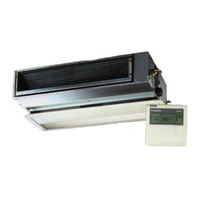
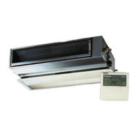
Sky-Air Indoor
Brand:
Daikin
| Category:
Air Conditioner
| Size: 7.24 MB
Table of Contents
Service Manual
1
Table of Contents
3
About this Manual
11
Combination Overview
12
System Outline
19
1 General Outline
21
What Is in this Chapter
21
Fcq35, 50, 60, 71B
22
Fcq100, 125B
24
Fcq71D
26
Fcq100, 125, 140D
28
Ffq25, 35, 50, 60B
30
Fbq35, 50B
32
Fbq60, 71B
34
Fbq100, 125B
36
Fdq125B
38
Fdq200, 250B
40
Fhq35, 50B
42
Fhq60, 71B
44
Fhq100B
46
Fhq125B
48
Fuq71B
50
Fuq100, 125B
52
Faq71B
54
Faq100B
56
Fdeq71, 100B
58
Fdeq125B
60
2 Specifications
63
What Is in this Chapter
63
Fcq - B
64
Fcq - D
65
Ffq - B
66
Fbq - B
67
Fdq - B
68
Fhq - B
69
Fuq - B
70
Faq - B
71
Technical Specifications
71
Electrical Specifications
71
Fdeq - B
72
What Is in this Chapter?
73
Indoor Piping
74
Pipe Connection Diameters
76
Piping Components
77
4 Wiring Diagrams
79
What Is in this Chapter
79
Fcq35, 50, 60B
80
Fcq71, 100, 125B
82
Fcq71, 100, 125, 140D
84
Ffq25, 35, 50, 60B
86
Fbq35, 50, 60B
88
Fbq71B
90
Fbq100, 125B
92
Fdq125, 200, 250B
94
Fhq35, 50, 60B
96
Fhq71, 100, 125B
98
Fuq71, 100, 125B
100
Faq71B
102
Faq100B
104
Fdeq71B
106
Fdeq100B
108
Fdeq125B
110
Switch Box Layout
113
What Is in this Chapter
113
Fcq35, 50, 60, 71B
114
Fcq100, 125B
115
Fcq71, 100, 125 140D
116
Ffq25, 35, 50, 60B
117
Fbq35, 50, 60, 71, 100, 125B
118
Fdq125, 200, 250B
119
Fhq35, 50, 60, 71, 100, 125B
120
Fuq71, 100, 125B
121
Faq71B
122
Faq100B
123
Fdeq71, 100, 125B
124
What Is in this Chapter
125
Fcq35, 50, 60B
126
Fcq71, 100, 125B
127
Fcq71, 100, 125, 140D
128
Ffq25, 35, 50, 60B
130
Fbq35, 50, 60, 71B & Fdeq71B
131
Fbq100, 125B & Fdeq100, 125B
132
Fdq125, 200, 250B
133
Fhq35, 50, 60B
134
Fhq71, 100, 125B
135
Fuq71, 100, 125B
136
Faq71B
137
Faq100B
138
What Is in this Chapter
141
Restart Standby
141
Automatic Restart
141
Forced Thermostat off
141
Freeze Prevention Function
141
Functions of Thermistors
142
Forced Operating Mode (Emergency Operation)
143
Outdoor Unit Identification Function
145
Simulated Operation Function
146
Restart Standby
147
Automatic Restart
148
Using Conditions for Remote Control Thermostat
149
Forced Thermostat off
151
Freeze Prevention Function
152
PMV Control
153
Thermostat Control
154
Drain Pump Control
155
Condensation Avoidance Control
157
Draft Avoidance Control 1
158
Draft Avoidance Control 2
159
Fan and Flap Operations
160
Indoor Unit Fan Control
161
Additional Checks for Troubleshooting
163
What Is in this Chapter
165
Checks
165
Overview of General Problems
165
Overview of General Problems
167
Equipment Does Not Operate
168
Equipment Operates but Does Not Provide Heating
174
Equipment Discharges White Mist
176
Equipment Produces Loud Noise or Shakes
177
Equipment Discharges Dust
178
Swing Flap Does Not Operate
180
Troubleshooting by LED Indications on the Indoor Unit
189
System Malfunctions
191
Overview of the Indoor Safety Devices
192
What Is in this Chapter?
193
Malfunctioning Indoor PCB
194
Malfunction of Drain Water Level System
195
Malfunctioning Drain System
197
Indoor Unit Fan Motor Lock
198
Malfunctioning Capacity Setting
200
Thermistor Abnormality
202
Malfunctioning Remote Controller Air Thermistor
204
Malfunctioning of Moisture Sensor System
205
What Is in this Chapter
209
Malfunction of Transmission between Indoor and Outdoor Unit (U4 or UF)
210
Remote Controller (U5)
213
Malfunction of Transmission between MAIN Remote Controller
213
And SUB Remote Controller
213
Malfunctioning Field Setting Switch
214
Centralized Address Setting Error
216
What Is in this Chapter?
217
Test Run Checks
218
What Is in this Chapter?
223
How to Change the Field Settings with the Wired Remote Control
224
How to Change the Field Settings with the Infrared Remote Control
226
Overview of the Field Settings on the Indoor Units
227
Overview of the Factory Settings on the Indoor Units
228
Setting the Ceiling Height
229
Setting the Filter Counter
230
Main/Sub Setting When Using Two Remote Controls
232
Setting the Centralized Group no
233
The Field Setting Levels
234
General Operation Data
238
Fbq100, 125B
243
Fbq60, 71B
243
Fdeq125B
243
Fcq35, 50, 60, 71B
244
Fcq100, 125B
246
Ffq25, 35, 50, 60B
248
Fbq35, 50B
250
Fbq60, 71B
252
Fbq100, 125B
254
Fdq125, 200, 250B
256
Fdeq71, 100B
258
Fdeq125B
260
Fcq71, 100, 125, 140D
262
Removal of Suction Grille
263
Removal of Air Filter
264
Removal of Decoration Panel
266
Removal of Horizontal Blade
268
Removal of Swing Motor
269
Removal of Switch Box
271
Removal of Pc Board
273
Removal of Humidity Sensor and Air Temperature Thermistor
275
Removal of Fan Motor
276
Removal of Drain Pan, Drain Pump, Float Switch
278
Removal of Heat Exchanger Temperature Thermistor
281
Ffq25, 50, 60B
282
Removal of Horizontal Vane
289
Removal of Fan Rotor and Fan Motor
295
Removal of Drain Pan
298
Removal of Drain Pump
299
Installation of Drain Pump
301
Replacement of Heat Exchanger Thermistor
304
Replacement of Heat Exchanger
306
Replacement of Pc Board
312
Replacement of Receiver Section of Infrared Remote Control
316
Fhq35, 50, 60, 71, 100, 125B
319
Removal of Air Filter and Suction Grille
320
Removal of Electrical Parts and Pc Boards
322
Removal of Fan Bearing
329
Removal of Bottom Panel and Drain Pan
331
Fuq71, 100, 125B
334
Removal of Fan
338
Removal of Air Flow Control Blade
349
Faq71B
351
Removal of Front Grille
354
Removal of Electrical Box
357
Removal of Heat Exchanger
358
Faq100B
362
Removal of Electrical Parts Box
365
Removal of Swing Louvre Unit
367
Removal of Fan Rotor
373
Daikin FBQ60B7V1 x 2 Service Manual (390 pages)
Brand:
Daikin
| Category:
Air Conditioner
| Size: 5.61 MB
Table of Contents
Service Manual
1
Table of Contents
3
What Is in this Chapter
3
What Is in this Chapter?
21
Fcq71D
26
Fcq100, 125, 140D
28
Ffq25, 35, 50, 60B
30
Fbq35, 50B
32
Fbq60, 71B
34
Fbq100, 125B
36
Fhq35, 50B
42
Fhq60, 71B
44
Fhq100B
46
Fhq125B
48
Fuq71B
50
Fuq100, 125B
52
Faq71B
54
Faq100B
56
Fdeq71, 100B
58
Fdeq125B
60
What Is in this Chapter?
63
2 Specifications
64
Technical Specifications
71
Electrical Specifications
71
3 Functional Diagrams
73
What Is in this Chapter
73
Indoor Piping
74
Pipe Connection Diameters
76
4 Wiring Diagrams
79
What Is in this Chapter
79
Fcq35, 50, 60B
80
Fcq71, 100, 125B
82
Fcq71, 100, 125, 140D
84
Ffq25, 35, 50, 60B
86
Fbq35, 50, 60B
88
Fbq71B
90
Fbq100, 125B
92
Fdq125, 200, 250B
94
Fhq35, 50, 60B
96
Fhq71, 100, 125B
98
Fuq71, 100, 125B
100
Faq71B
102
Faq100B
104
Fdeq71B
106
Fdeq100B
108
Fdeq125B
110
5 Switch Box Layout
113
What Is in this Chapter
113
Fcq35, 50, 60, 71B
114
Fcq100, 125B
115
Fcq71, 100, 125 140D
116
Ffq25, 35, 50, 60B
117
Fbq35, 50, 60, 71, 100, 125B
118
Fdq125, 200, 250B
119
Fhq35, 50, 60, 71, 100, 125B
120
Fuq71, 100, 125B
121
Faq71B
122
Faq100B
123
Fdeq71, 100, 125B
124
What Is in this Chapter?
125
Fcq35, 50, 60B
126
Fcq71, 100, 125B
127
Fcq71, 100, 125, 140D
128
Ffq25, 35, 50, 60B
130
Fbq35, 50, 60, 71B & Fdeq71B
131
Fbq100, 125B & Fdeq100, 125B
132
Fdq125, 200, 250B
133
Fhq35, 50, 60B
134
Fhq71, 100, 125B
135
Fuq71, 100, 125B
136
Faq71B
137
Faq100B
138
Functions of Thermistors
142
Forced Operating Mode (Emergency Operation)
143
Outdoor Unit Identification Function
145
Simulated Operation Function
146
Restart Standby
147
Automatic Restart
148
Using Conditions for Remote Controller Thermostat
149
Forced Thermostat off
151
Freeze Prevention Function
152
PMV Control
153
Thermostat Control
154
Drain Pump Control
155
Condensation Avoidance Control
157
Draft Avoidance Control 1
158
Draft Avoidance Control 2
159
Fan and Flap Operations
160
Indoor Unit Fan Control
161
Additional Checks for Troubleshooting
163
What Is in this Chapter
165
General Troubleshooting Flowchart
166
Overview of General Problems
167
Equipment Does Not Operate
168
Equipment Operates but Does Not Provide Heating
174
Equipment Discharges White Mist
176
Equipment Produces Loud Noise or Shakes
177
Equipment Discharges Dust
178
Swing Flap Does Not Operate
180
Procedure of Self-Diagnosis by Remote Controller
182
Fault-Diagnosis by Wired Remote Controller
183
Troubleshooting by LED Indications on the Indoor Unit
189
Troubleshooting by Remote Controller Display / LED Display
190
System Malfunctions
191
Overview of the Indoor Safety Devices
192
What Is in this Chapter
193
Malfunctioning Indoor PCB
194
Malfunction of Drain Water Level System
195
Malfunctioning Drain System
197
Indoor Unit Fan Motor Lock
198
Malfunctioning Capacity Setting
200
Thermistor Abnormality
202
Malfunctioning Remote Controller Air Thermistor
204
Malfunctioning of Moisture Sensor System
205
What Is in this Chapter
207
Malfunction of Transmission between Indoor and Outdoor Unit (U4 or UF)
208
Malfunction of Transmission between Indoor Unit and Remote Controller (U5)
210
Malfunction of Transmission between MAIN Remote Controller
211
And SUB Remote Controller
211
Malfunctioning Field Setting Switch
212
Centralized Address Setting Error
214
What Is in this Chapter
215
Indoor Unit: Checking the Power Supply Wave Form
215
What Is in this Chapter?
227
Test Run Checks
228
Setting the Wireless Remote Controller
229
What Is in this Chapter?
233
How to Change the Field Settings with the Wired Remote Controller
234
Overview of the Field Settings on the Indoor Units
237
Overview of the Factory Settings on the Indoor Units
238
Setting the Ceiling Height
239
Setting the Filter Counter
240
Setting the Centralized Group no
243
The Field Setting Levels
244
3 Test Run and Operation Data
247
General Operation Data
248
Fcq35, 50, 60, 71B
253
Fcq35, 50, 60, 71B
254
Fcq100, 125B
256
Ffq25, 35, 50, 60B
258
Fbq35, 50B
260
Fbq60, 71B
262
Fbq100, 125B
264
Fdq125, 200, 250B
266
Fdeq71, 100B
268
Fdeq125B
270
Fcq71, 100, 125, 140D
272
Removal of Humidity Sensor and Air Temperature Thermistor
285
Removal of Heat Exchanger Temperature Thermistor
291
Ffq25, 50, 60B
292
Removal of Horizontal Vane
299
Installation of Drain Pump
311
Replacement of Heat Exchanger Thermistor
314
Replacement of Heat Exchanger
316
Replacement of Pc Board
322
Fhq35, 50, 60, 71, 100, 125B
329
Removal of Electrical Parts and Pc Boards
332
Removal of Fan Bearing
339
Removal of Bottom Panel and Drain Pan
341
Fuq71, 100, 125B
344
Removal of Fan
348
Removal of Air Flow Control Blade
359
Faq71B
361
Removal of Front Grille
364
Removal of Electrical Box
367
Faq100B
372
Removal of Electrical Parts Box
375
Removal of Swing Louvre Unit
377
Removal of Fan Rotor
383
Advertisement
Daikin FBQ60B7V1 x 2 Service Manual (314 pages)
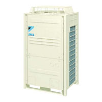
R-410A, 50Hz
Brand:
Daikin
| Category:
Heat Pump
| Size: 17.46 MB
Table of Contents
Table of Contents
2
Introduction
7
Safety Cautions
7
Preface
11
Skyair Inverter GQI III Series
12
Part 1 General Information
14
Combination
15
Combination Overview
15
Combination Matrix
16
External Appearance
17
Model Name and Power Supply
18
Part 2 Specifications
20
Specifications
21
RZQ71C7, 100C7, 125C7 and 140C7 (Single Phase)
21
RZQS71C7, 100C7, 125C7 and 140C7 (Single Phase)
25
Part 3 Remote Controller
30
Wired Remote Controller
31
Features
31
Installation
33
Wireless Remote Controller
35
Features
35
Method of Operating Remote Controller
37
The INSPECTION / TEST Button
37
Maintenance Mode Setting
38
Operation of the Remote Controller's Inspection / Test Operation Button
40
Remote Controller Service Mode
41
Part 4 Functional Description
42
General Functionality
44
Functions of Thermistors
44
Forced Operating Mode (Emergency Operation)
46
Outdoor Unit Identification Function
48
Simulated Operation Function
49
Restart Standby
50
Automatic Restart
51
Using Conditions for Remote Controller Thermostat
52
Forced Thermostat off
54
Test Run Control
55
4-Way Valve Control
56
Pump down Operation
57
Defrost Operation
58
Freeze Prevention Function
60
PMV Control
61
Preheating Operation Control
62
Crankcase Heater Control
63
Indoor Unit Functional Concept
64
Thermostat Control
64
Drain Pump Control
65
Condensation Avoidance Control
66
Draft Avoidance Control 1
67
Draft Avoidance Control 2
68
Fan and Flap Operation
69
Indoor Unit Fan Control
70
Outdoor Unit Functional Concept
72
Function Outline in Cooling Mode
72
Function Outline in Heating Mode
73
Frequency Regulating Functions
74
Starting Frequency Control
74
Starting Control
75
General Frequency Control
76
Low Pressure Protection Control
78
High Pressure Protection Control
80
Discharge Pipe Temperature Control
81
Suction Pipe Superheat Protection Control (Heating Mode)
82
Inverter Current Protection Control
83
Protection Control by Overall Current
84
Inverter Cooling Fin Temperature Control
85
Pressure Difference Control
86
Oil Recovery Operation
88
Expansion Valve Regulating Functions
89
Expansion Valve Control at Startup
89
General Expansion Valve Control
90
Discharge Pipe Temperature Protection Control
91
Outdoor Unit Fan Speed Control
92
Part 5 Test Operation
94
Test Operation
95
Test Run Checks
95
Setting the Wireless Remote Controller
96
Field Settings
100
How to Change the Field Settings with the Wired Remote Controller
100
How to Change the Field Settings with the Wireless Remote Controller
102
Overview of the Field Settings on the Indoor Units
103
Overview of the Factory Settings on the Indoor Units
104
MAIN/SUB Setting When Using Two Remote Controllers
105
Setting the Centralized Group no
106
The Field Setting Levels
107
Overview of the Field Settings on the Outdoor Units
110
Overview of the Factory Settings on the Outdoor Units
110
Existence of DIP Switch and BS Button
111
Quiet (Low Noise) Operation
117
I-Demand Function
119
Setting for Low Humidity Application
121
Defrost Start Setting
126
Test Run and Operation Data
127
General Operation Data
127
Operation Range
130
Part 6 Troubleshooting
132
How to Handle Request for Maintenance
134
General Troubleshooting Flowchart
134
Troubleshooting Based on Equipment Condition
135
Overview of General Problems
135
Equipment Does Not Operate
136
Indoor Fan Operates, but Compressor Does Not
138
Cooling/Heating Operation Starts but Stops Immediately
140
After Unit Shuts Down, It Cannot be Restarted for a While
142
Equipment Operates but Does Not Provide Cooling
144
Equipment Operates but Does Not Provide Heating
146
Equipment Discharges White Mist
148
Equipment Produces Loud Noise or Shakes
149
Equipment Discharges Dust
151
Remote Controller LCD Displays "88
152
Swing Flap Does Not Operate
153
Procedure of Self-Diagnosis by Remote Controller
155
The Inspection/Test Button
155
Fault-Diagnosis by Wired Remote Controller
156
Fault-Diagnosis by Wireless Remote Controller
157
Remote Controller Display Malfunction Code and Contents
161
Troubleshooting by LED Indications
163
Troubleshooting by LED on the Indoor Units
163
Troubleshooting by LED on Outdoor Unit PC Board
164
Troubleshooting by Remote Controller Display / LED Display
165
Indoor Malfunctions
165
Outdoor Malfunctions
166
System Malfunctions
167
Overview of the Outdoor Safety Devices
168
Overview of the Indoor Safety Devices
169
A1" Malfunctioning Indoor PC Board
170
A3" Malfunction of Drain Water Level System
171
A6" Indoor Unit Fan Motor Lock
173
A7" Swing Flap Motor Malfunction / Lock
175
A8" Abnormal Power Supply Voltage
177
AF" Malfunctioning Drain System
178
AJ" Malfunctioning Capacity Setting
180
C1" Failure of Transmission (between Indoor Unit PC Board and Fan PC Board)
182
C4", "C9" Thermistor Abnormality
184
C6" Failure of Combination (between Indoor Unit PC Board and Fan PC Board)
186
CJ" Malfunctioning Remote Controller Air Thermistor
187
CC" Humidity Sensor System Malfunction
188
E1" Failure of Outdoor Unit PC Board
189
E3" Abnormal High Pressure (Detected by the HPS)
190
E4" Actuation of Low Pressure Sensor: Single Phase C Series
192
E5" Compressor Motor Lock
194
E7" Malfunction of Outdoor Unit Fan Motor
196
E9" Malfunction of Electronic Expansion Valve
199
F3" Malfunctioning in Discharge Pipe Temperature
202
H3" Malfunctioning HPS System
204
H9", "J3", "J5", "J6", "J7", "J8" Malfunction of Thermistor System
205
J1" Malfunction of Pressure Sensor
206
L1" Faulty Outdoor PC Board
208
L4" Radiation Fin Temperature Increased
210
L5" DC Output Overcurrent (Instantaneous)
212
L8" Electronic Thermal (Time Lag)
214
L9" Stall Prevention (Time Lag)
216
LC" Malfunction of Transmission System (between Control and Inverter PC Board)
218
P1" Open Phase or Power Supply Voltage Imbalance
220
P4" Malfunction of Radiator Fin Temperature Thermistor
221
PJ" Failure of Capacity Setting
222
U0" Gas Shortage (Malfunction)
223
U2" Abnormal Power Supply Voltage
225
U4", "UF" Malfunction of Transmission between Indoor and Outdoor Unit
227
UF" Malfunction of Transmission between Indoor and Outdoor Unit / Piping and Wiring Mismatch / Gas Shortage
230
U5" Malfunction of Transmission between Indoor Unit and Remote Controller
231
U8" Malfunction of Transmission between MAIN Remote Controller and SUB Remote Controller
232
UA" Malfunctioning Field Setting Switch
233
UC" Centralized Address Setting Error
235
Part 7 Appendix
252
Dimensions
253
Rzq71C7, Rzqs71·100C7V1B
253
Rzq100~140C, Rzqs125·140C7V1B
254
Installation and Service Space (RZQ100~140C7, RZQS125~140C7)
255
Non Stacked
255
Stacked
256
Multiple Rows
256
Piping Diagrams
257
Piping Symbol
257
Pair System
258
Twin System
260
Triple System
262
Double Twin System
263
Pipe Connection Diameters
264
Re-Using Existing Field Piping
265
Wiring Diagrams
271
Outdoor Unit
271
Switch Box Layout
273
Rzq71C7, Rzqs71·100C7V1B
273
Rzq100~140C7, Rzqs125·140C7V1B
274
PCB Layout
275
Rzq71C7, Rzqs71·100C7V1B
275
Rzq100~140C7, Rzqs125·140C7V1B
276
Part 8 Removal Procedure
278
Rzq71C7, Rzqs71·100C7V1B
279
Removal of Outside Panels and Related Parts
279
Removal of Propeller Fan and Fan Motor
280
Removal of Switch Box
281
Removal of PC Board Assy (1)
282
Removal of PC Board Assy (2)
283
Removal of PC Board Assy (3)
284
Removal of Low Pressure Sensor, Electronic Expansion Valve, and Others
285
Removal of Thermistor
286
Removal of Four Way Valve
287
Removal of Compressor
288
Rzq100~140C7, Rzqs125·140C7V1B
289
Removal of Outside Panels
289
Removal of Propeller Fan and Fan Motor
290
Removal of Switch Box
291
Removal of PC Board
292
Removal of Pressure Sensor, Electronic Expansion Valve, and Others
293
Removal of Thermistor
294
Removal of Four Way Valve
295
Removal of Compressor
296
Daikin FBQ60B7V1 x 2 Service Manual (222 pages)
R-410A Heat Pump 50Hz
Brand:
Daikin
| Category:
Heat Pump
| Size: 3.91 MB
Table of Contents
Table of Contents
2
Introduction
6
Safety Cautions
6
Preface
10
Part 1 General Information
14
Model Name and Power Supply
15
Possible Combinations and Standard Capacity for Twin, Triple and Double Twin Operation
16
External Appearance
17
Part 2 Specifications
18
Specifications
19
Outdoor Units
19
Electric Characteristics
20
Part 3 Remote Controller
22
Wired Remote Controller
23
Features
23
Installation
25
Wireless Remote Controller
27
Features
27
Method of Operating Remote Controller
29
The INSPECTION / TEST Button
29
Maintenance Mode Setting
30
Operation of the Remote Controller's Inspection / Test Operation Button
32
Remote Controller Service Mode
33
Part 4 Field Setting
34
Field Setting of Indoor Unit
35
Field Setting from Remote Controller
35
Setting Contents and Code No. - Skyair Indoor Unit
37
Skyair Indoor Unit
37
Detailed Explanation of Setting Modes
38
Filter Sign Setting
38
Fan Speed off When Thermostat Is off
39
Automatic Operation Mode Control
40
Fan Speed Changeover When Thermostat off
40
Auto Restart after Power Failure Reset
40
Air Flow Direction Setting
41
Field Setting of Outdoor Unit
43
Field Setting from Remote Controller
43
Explanation of each Setting
44
Field Setting by Demand Adapter
46
Demand Operation by External Input
46
Field Setting from Outdoor Unit PC Board
49
Function of each Switch
49
Emergency Operation
55
Emergency Operation (Forced Operation) Setting Procedure
55
Test Operation Setting Procedure
56
Emergency Operation (When the Remote Controller Is Lost)
56
Part 5 Function and Operation
58
Indoor Unit
59
Function Details
59
Drain Pump Control
62
Fan Airflow Direction Adjustment Control
62
Electric Heater Control
62
Dew Condensation Prevention Control
63
Defrost Control
64
Cold Air Prevention Control
64
Outdoor Unit
65
Function List
65
Flow Chart of Outdoor Unit
66
Table of Functions and Operations
68
Function Details
72
Startup Control
73
Function Control
74
Electronic Expansion Valve Pi Control
74
Protection Control
76
Low Pressure Protection Control
76
High Pressure Protection Control
76
Pump down Residual Operation
77
Defrosting Operation
79
List of Electrical and Functional Parts
82
Outdoor Unit
82
Operation Range
83
Operation Limits
83
Part 6 Troubleshooting
84
Maintenance Inspections
86
Optimal Operation Condition
86
Refrigerant Saturation Curve (R-410A)
89
Cautions in Handling New Refrigerant
90
Refrigerant Charge
92
Flaring and Flare Nut
92
Air Tighteness Test
93
Troubleshooting Based on Equipment Condition
94
Equipment Does Not Operate
95
Indoor Fan Operates, but Compressor Does Not
96
Cooling/Heating Operation Starts but Stops Immediately
98
After Equipment Shuts Down, It Cannot be Restarted for a While
100
Equipment Operates but Does Not Provide Cooling
101
Equipment Operates but Does Not Provide Heating
103
Equipment Discharges White Mist
104
Equipment Produces Loud Noise or Shakes
105
Equipment Discharges Dust
106
Remote Controller LCD Displays "88
107
Swing Flap Does Not Move
108
Procedure of Self-Diagnosis by LED
109
Troubleshooting by LED on Outdoor Unit PC Board
109
Diagnosis by Remote Controller
110
Confirm Method of Malfunction Code
110
Remote Controller Display Malfunction Code and Contents
113
A1" Failure of Indoor Unit PC Board
115
A3" Malfunction of Drain Water Level System (Float Type)
116
A6" Malfunction of Indoor Unit Fan Motor
118
A6" Malfunction of Indoor Unit Fan Motor
120
A6" Indoor Unit Fan Motor Overload, Overcurrent, Lock
121
A7" Malfunction of Swing Flap Motor
123
AF" Failure of Drain System
124
AJ" Malfunction of Capacity Determination Device
125
C4" Malfunction of Heat Exchange Temperature Sensor System
126
C9" Malfunction of Suction Air Temperature Sensor System
127
CC" Malfunction of Humidity Sensor System
128
CJ" Malfunction of Remote Controller Air Thermistor
129
E1" Failure of Outdoor Unit PC Board
130
E3" Abnormal High Pressure Level
131
E4" Low Pressure System Malfunction
133
E5" Inverter Compressor Motor Lock
135
E7" Malfunction of Outdoor Unit Fan Motor
136
E9" Malfunction of Moving Part of Electronic Expansion Valve
139
F3" Malfunction of Discharge Pipe Temperature
141
H3" Abnormal High Pressure Switch
143
H7" Abnormal Outdoor Fan Motor Signal
145
H9" "J3" "J5" "J6" "J7" "J8" Malfunction of Thermistor System
147
JA" Malfunction of High Pressure Sensor
149
JC" Malfunction of Low Pressure Sensor
151
L1" Faulty Outdoor Inverter PC Board
153
L4" Radiation Fin Temperature Increased
154
L5" Momentary Overcurrent of Inverter Compressor
156
L8" Inverter Compressor Overcurrent
158
L9" Compressor Inverter Start up Error
160
LC" Malfunction of Transmission between Inverter and Control PC Board
162
P1" Inverter Over-Ripple Protection
165
PJ" Defective Combination of Inverter and Fan Driver
166
U0" Gas Shortage (Malfunction)
167
U1" Reverse Phase
168
U2" Power Supply Insufficient or Instantaneous Failure
169
U4" Malfunction of Transmission (between Indoor and Outdoor Unit)
172
U5" Malfunction of Transmission (between Indoor Unit and Remote Controller)
174
U8" Transmission Error between Main Remote Controller and Sub Remote Controller
175
U9" Malfunction of Transmission between Indoor and Outdoor Units in the same System
176
UA" Malfunction of Field Setting Switch and Transmission Line
178
UC" Centralized Address Duplicated
180
UE" Malfunction of Transmission between Centralized Controller and Indoor Unit
181
UF" Transmission System Malfunction (between Indoor and Outdoor Units)
183
Part 7 Appendix
196
Items Improved from the Existing Models
197
Piping Diagrams
198
Pair
198
Twin
199
Triple
200
Double Twin
201
Wiring Diagrams
202
Outdoor Unit
202
Daikin FBQ60B7V1 x 2 Operation Manual (10 pages)
Brand:
Daikin
| Category:
Air Conditioner
| Size: 0.9 MB
Table of Contents
Table of Contents
3
What to Do before Operation
3
Names and Functions of Parts
3
Operation Range
4
Installation and Installation Site
4
Operation Procedure
4
Optimum Operation
4
Not a Malfunction of the Air Conditioner
5
Troubleshooting
6
Maintenance
6
Daikin FBQ60B7V1 x 2 Operation Manual (10 pages)
Split system air conditioners
Brand:
Daikin
| Category:
Air Conditioner
| Size: 0.87 MB
Table of Contents
Table of Contents
4
What to Do before Operation
4
Names and Functions of Parts
4
Operation Range
4
Installation Site
4
Operation Procedure
5
Optimum Operation
5
Not a Malfunction of the Air Conditioner
5
Troubleshooting
6
Maintenance
7
Advertisement
Related Products
Daikin FBQ60BV1
Daikin FBQ60BVL
Daikin FBQ60BV1A
Daikin Super Multi NX FBQ60C7VEB
Daikin FBQ60D2VEB
Daikin FBQ60C8VEB
Daikin FBQ60B8V1
Daikin FBQ60D
Daikin FBQ60EVE4
Daikin FBQ140DVET
Daikin Categories
Air Conditioner
Heat Pump
Remote Control
Chiller
Fan
More Daikin Manuals
Login
Sign In
OR
Sign in with Facebook
Sign in with Google
Upload manual
Upload from disk
Upload from URL