Daikin FCQ35B7V1 Service Manual
Hide thumbs
Also See for FCQ35B7V1:
- Technical data manual (20 pages) ,
- Service manual (381 pages) ,
- Operation manual (10 pages)
Table of Contents
Advertisement
Advertisement
Table of Contents
Troubleshooting

Related Manuals for Daikin FCQ35B7V1


Summary of Contents for Daikin FCQ35B7V1
-
Page 1: Service Manual
ESIE05-04 Service Manual R-410A Sky-Air Indoor... -
Page 3: Table Of Contents
ESIE05-04 Table of Contents Introduction About This Manual .................. i–i Combination Overview ................i–ii Part 1 System Outline General Outline What Is in This Chapter? ................ 1–3 FCQ35, 50, 60, 71B ................1–4 FCQ100, 125B ..................1–6 FCQ71D ....................1–8 FCQ100, 125, 140D ................ - Page 4 ESIE05-04 Functional Diagrams What Is in This Chapter? ................. 1–55 Indoor Piping.................... 1–56 Pipe Connection Diameters ..............1–58 Piping Components ................. 1–59 Wiring Diagrams What Is in This Chapter? ................. 1–61 FCQ35, 50, 60B ..................1–62 FCQ71, 100, 125B ................... 1–64 FCQ71, 100, 125, 140D................
- Page 5 ESIE05-04 PCB Layout What Is in This Chapter? ................ 1–107 FCQ35, 50, 60B ..................1–108 FCQ71, 100, 125B .................. 1–109 FCQ71, 100, 125, 140D ................1–110 FFQ25, 35, 50, 60B ................1–112 FBQ35, 50, 60, 71B & FDEQ71B ............1–113 FBQ100, 125B &...
- Page 6 ESIE05-04 Part 2 Functional Description Functional concept What Is in This Chapter? ................. 2–3 Functions of Thermistors ................. 2–4 Forced Operating Mode (Emergency Operation)........2–5 Outdoor Unit Identification Function ............2–7 Simulated Operation Function ..............2–8 Restart Standby ..................2–9 Automatic Restart ..................
- Page 7 ESIE05-04 Part 3 Troubleshooting Troubleshooting What Is in This Chapter? ................ 3–3 General Troubleshooting Flowchart ............3–4 Overview of General Problems ............... 3–5 Procedure of Self-Diagnosis by Remote Controller ........ 3–20 Fault-diagnosis by Wired Remote Controller .......... 3–21 Fault-diagnosis by Wireless Remote Controller ........3–22 Overview of Error Codes.................
- Page 8 ESIE05-04 Additional Checks for Troubleshooting What Is in This Chapter? ................. 3–53 Indoor Unit: Checking the Fan Motor Hall IC ........... 3–54 Indoor Unit: Checking the Power Supply Wave Form......3–55 Checking the Thermistors ................ 3–56 Resistance Conversion Table (Ambient, Coil, Fin) ......... 3–57 Evaluation of Abnormal High Pressure ............
- Page 9 ESIE05-04 Part 4 Commissioning and Test Run Pre-Test Run Checks What Is in This Chapter? ................ 4–3 Test Run Checks ..................4–4 Setting the Wireless Remote Controller ..........4–5 Field Settings What Is in This Chapter? ................ 4–9 How to Change the Field Settings with the Wired Remote Controller ...................
- Page 10 ESIE05-04 Part 5 Disassembly and Maintenance Disassembly and Maintenance What Is in This Chapter? ................. 5–3 FCQ35, 50, 60, 71B ................. 5–4 FCQ100, 125B ..................5–6 FFQ25, 35, 50, 60B ................. 5–8 FBQ35, 50B ..................... 5–10 FBQ60, 71B ..................... 5–12 FBQ100, 125B ..................
- Page 11 ESIE05-04 Introduction Part 0 Introduction About This Manual Target group This service manual is intended for and should only be used by qualified engineers. Purpose of this This service manual contains all the information you need to do the necessary repair and maintenance manual tasks for the R-410A Sky Air Indoor Units.
- Page 12 Pair split outdoor The table below contains the possible combinations between indoor units and pair split outdoor units. Non Inverter Inverter Outdoor unit Cooling Only Cooling Only Heat Pump Indoor unit FCQ35B7V1 FCQ50B7V1 FCQ60B7V1 FFQ25B(7)V1B FFQ35B(7)V1B FFQ50B(7)V1B FFQ60B(7)V1B FBQ35B7V1 FBQ50B7V1...
- Page 13 ESIE05-04 Introduction Multi split outdoor The table below contains the possible combinations between indoor units and multi split outdoor units. Inverter Outdoor unit Cooling Only Heat Pump Indoor unit FCQ35B7V1 FCQ50B7V1 FCQ60B7V1 FFQ25B(7)V1B FFQ35B(7)V1B FFQ50B(7)V1B FFQ60B(7)V1B FBQ35B7V1 FBQ50B7V1 FBQ60B7V1 FHQ35BUV1B...
- Page 14 Sky Air outdoor The table below contains the possible combinations between indoor units and Sky Air outdoor units. Non Inverter Inverter Outdoor unit Cooling Only Heat Pump Heat Pump Indoor unit FCQ35B7V1 FCQ50B7V1 FCQ60B7V1 FCQ71B7V3B FCQ100B7V3B FCQ125B7V3B FCQ71DV3B FCQ100DV3B FCQ125DV3B...
- Page 15 ESIE05-04 Introduction Non Inverter Inverter Outdoor unit Cooling Only Heat Pump Heat Pump Indoor unit FHQ35BUV1B FHQ50BUV1B FHQ60BUV1B FHQ71BUV3B FHQ100BUV3B FHQ125BUV3B FUQ71BV3B FUQ100BV3B FUQ125BV3B FAQ71BV3B FAQ100BV3B...
- Page 16 Introduction ESIE05-04 Combination matrix Possible indoor combination (Standard capacity for twin, triple and double twin operation) Twin Triple Double Twin Outdoor models 35-35 RZQ71B8V3B (KHRQ22M20TA7) RZQ100B8V3B 50-50 35-35-35 RZQ100B7W1B (KHRQ22M20TA7) (KHRQ127H7) RZQ125B8V3B 60-60 50-50-50 35-35-35-35 RZQ125B7W1B (KHRQ22M20TA7) (KHRQ127H7) (3x KHRQ22M20TA7) 71-71 50-50-50 35-35-35-35...
- Page 17 ESIE05-04 Introduction Combination matrix Possible indoor combination (Standard capacity for twin, triple and double twin operation) Twin Triple Double Twin Outdoor models 60-60-60 50-50-50-50 100-100 RZQ200B7W1B 71-71-71 (3x KHQ22M20TA7) (KHRQ22M20TA7) (KHRQ250H7) 125-125 60-60-60-60 RZQ250B7W1B (KHRQ22M20TA7) (3x KHRQ22M20TA7) Notes: 1 Possible indoor types: FCQ50~125 FFQ50, 60 FHQ50~125...
- Page 18 Introduction ESIE05-04 Combination matrix Possible indoor combination (Standard capacity for twin and triple operation) Twin Triple Outdoor models RQ71B7V3/W1 35-35 RR71B7V3/W1 (KHRQ22M20TA7) RQ100B7V3/W1 50-50 50-60 35-71 35-35-35 RR100B7V3/W1 (KHRQ22M20TA7) (KHRQ22M20TA7) (KHRQ22M20TA7) (KHRQ127H7) RQ125B7W1 60-60 50-71 50-50-50 RR125B7W1 (KHRQ22M20TA7) (KHRQ22M20TA7) (KHRQ127H7) Notes: 1 Possible indoor types: FCQ35~71...
- Page 19 ESIE05-04 Part 1 System Outline What is in this part? This part contains the following chapters: Chapter See page 1–General Outline 1–3 2–Specifications 1–45 3–Functional Diagrams 1–55 4–Wiring Diagrams 1–61 5–Switch Box Layout 1–95 6–PCB Layout 1–107 Part 1 – System Outline 1–1...
- Page 20 ESIE05-04 1–2 Part 1 – System Outline...
-
Page 21: What Is In This Chapter?
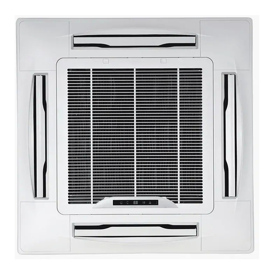
ESIE05-04 General Outline Part 1 General Outline What Is in This Chapter? Introduction This chapter contains the following information on the indoor units: Outlook and dimensions Components General outline This chapter contains the following general outlines: General outline See page 1.2–FCQ35, 50, 60, 71B 1–4 1.3–FCQ100, 125B... - Page 22 General Outline ESIE05-04 FCQ35, 50, 60, 71B Outlook and The illustration below shows the outlook and the dimensions of the unit (mm). dimensions 1–4 Part 1 – System Outline...
- Page 23 ESIE05-04 General Outline Components The table below contains the different components of the unit. Component Liquid pipe connection Gas pipe connection Drain pipe connection Power supply connection Transmission wiring connection Air outlet Air suction grille Water supply intake for drain Corner decoration cover Drain hose Part 1 –...
- Page 24 General Outline ESIE05-04 FCQ100, 125B Outlook and The illustration below shows the outlook and the dimensions of the unit (mm). dimensions 1–6 Part 1 – System Outline...
- Page 25 ESIE05-04 General Outline Components The table below contains the different components of the unit. Component Liquid pipe connection Gas pipe connection Drain pipe connection Power supply connection Transmission wiring connection Air discharge outlet Air suction grille Water supply intake for drain Corner decoration cover Drain hose Part 1 –...
-
Page 26: Fcq71D
General Outline ESIE05-04 FCQ71D Outlook and The illustration below shows the outlook and the dimensions of the unit (mm). dimensions 1–8 Part 1 – System Outline... - Page 27 ESIE05-04 General Outline Components The table below contains the different components of the unit. Component Liquid pipe connection Gas pipe connection Drain pipe connection Power supply / Wiring / Remote controller connection Air outlet Suction grille Corner decoration cover Drain hose (accessory) Part 1 –...
-
Page 28: Fcq100, 125, 140D
General Outline ESIE05-04 FCQ100, 125, 140D Outlook and The illustration below shows the outlook and the dimensions of the unit (mm). dimensions 1–10 Part 1 – System Outline... - Page 29 ESIE05-04 General Outline Components The table below contains the different components of the unit. Component Liquid pipe connection Gas pipe connection Drain pipe connection Power supply / Wiring / Remote controller connection Power supply connection Air-Outlet Suction grille Corner decoration cover Drain hose (accessory) Part 1 –...
-
Page 30: Ffq25, 35, 50, 60B
General Outline ESIE05-04 FFQ25, 35, 50, 60B Outlook and The illustration below shows the outlook and the dimensions of the unit (mm). dimensions 1–12 Part 1 – System Outline... - Page 31 ESIE05-04 General Outline Components The table below contains the different components of the unit. Component Liquid pipe connection Gas pipe connection Drain pipe connection Power supply connection Remote control code and control wiring connection Air discharge outlet Suction grille Drain hose Part 1 –...
-
Page 32: Fbq35, 50B
General Outline ESIE05-04 FBQ35, 50B Outlook and The illustration below shows the outlook and the dimensions of the unit (mm). dimensions 1–14 Part 1 – System Outline... - Page 33 ESIE05-04 General Outline Components The table below contains the different components of the unit. Component Liquid pipe connection Gas pipe connection Drain pipe connection Remote controller wiring connection Power supply connection Drain hole Air filter Air suction side Air discharge side Nameplate Part 1 –...
-
Page 34: Fbq60, 71B
General Outline ESIE05-04 FBQ60, 71B Outlook and The illustration below shows the outlook and the dimensions of the unit (mm). dimensions 1–16 Part 1 – System Outline... - Page 35 ESIE05-04 General Outline Components The table below contains the different components of the unit. Component Liquid pipe connection Gas pipe connection Drain pipe connection Remote controller wiring connection Power supply connection Drain hole Air filter Air suction side Air discharge side Nameplate Part 1 –...
-
Page 36: Fbq100, 125B
General Outline ESIE05-04 FBQ100, 125B Outlook and The illustration below shows the outlook and the dimensions of the unit (mm). dimensions 1–18 Part 1 – System Outline... - Page 37 ESIE05-04 General Outline Components The table below contains the different components of the unit. Component Liquid pipe connection Gas pipe connection Drain pipe connection Remote controller wiring connection Power supply connection Drain hole Air filter Air suction side Air discharge side Nameplate Part 1 –...
- Page 38 General Outline ESIE05-04 1.10 FDQ125B Outlook and The illustration below shows the outlook and the dimensions of the unit (mm). dimensions 1–20 Part 1 – System Outline...
- Page 39 ESIE05-04 General Outline Components The table below contains the different components of the unit. Component Power supply instake Drain connection Gas pipe connection single union Liquid pipe connection single union Filter Part 1 – System Outline 1–21...
- Page 40 General Outline ESIE05-04 1.11 FDQ200, 250B Outlook and The illustration below shows the outlook and the dimensions of the unit (mm). dimensions 1–22 Part 1 – System Outline...
- Page 41 ESIE05-04 General Outline Components The table below contains the different components of the unit. Component Power supply instake Drain connection Gas pipe connection Liquid pipe connection Filter Part 1 – System Outline 1–23...
-
Page 42: Fhq35, 50B
General Outline ESIE05-04 1.12 FHQ35, 50B Outlook and The illustration below shows the outlook and the dimensions of the unit (mm). dimensions 1–24 Part 1 – System Outline... - Page 43 ESIE05-04 General Outline Components The table below contains the different components of the unit. Component Air outlet Air suction grille Air filter Gas pipe connection Liquid pipe connection Drain pipe connection Earth terminal (Inside the electric components box) Suspension bracket Backward piping and wiring connection opening lid Upward piping and wiring connection opening lid Right side pipe connection...
-
Page 44: Fhq60, 71B
General Outline ESIE05-04 1.13 FHQ60, 71B Outlook and The illustration below shows the outlook and the dimensions of the unit (mm). dimensions 1–26 Part 1 – System Outline... - Page 45 ESIE05-04 General Outline Components The table below contains the different components of the unit. Component Air outlet Air suction grille Air filter Gas pipe connection Liquid pipe connection Drain pipe connection Earth terminal (Inside the electric components box) Suspension bracket Backward piping and wiring connection opening lid Upward piping and wiring connection opening lid Right side pipe connection...
-
Page 46: Fhq100B
General Outline ESIE05-04 1.14 FHQ100B Outlook and The illustration below shows the outlook and the dimensions of the unit (mm). dimensions 1–28 Part 1 – System Outline... - Page 47 ESIE05-04 General Outline Components The table below contains the different components of the unit. Component Air outlet Air suction grille Air filter Gas pipe connection Liquid pipe connection Drain pipe connection Earth terminal (Inside the electric components box) Suspension bracket Backward piping and wiring connection opening lid Upward piping and wiring connection opening lid Right side pipe connection...
-
Page 48: Fhq125B
General Outline ESIE05-04 1.15 FHQ125B Outlook and The illustration below shows the outlook and the dimensions of the unit (mm). dimensions 1–30 Part 1 – System Outline... - Page 49 ESIE05-04 General Outline Components The table below contains the different components of the unit. Component Air outlet Air suction grille Air filter Gas pipe connection Liquid pipe connection Drain pipe connection Earth terminal (Inside the electric components box) Suspension bracket Backward piping and wiring connection opening lid Upward piping and wiring connection opening lid Right side pipe connection...
-
Page 50: Fuq71B
General Outline ESIE05-04 1.16 FUQ71B Outlook and The illustration below shows the outlook and the dimensions of the unit (mm). dimensions 1–32 Part 1 – System Outline... - Page 51 ESIE05-04 General Outline Components The table below contains the different components of the unit. Component Liquid pipe connection Gas pipe connection Drain pipe connection Air outlet Air suction grille Corner decoration cover Right pipe and wiring connection Rear pipe and wiring connection Cover for upwards pipe and wiring connection Accessory drain elbow Part 1 –...
-
Page 52: Fuq100, 125B
General Outline ESIE05-04 1.17 FUQ100, 125B Outlook and The illustration below shows the outlook and the dimensions of the unit (mm). dimensions 1–34 Part 1 – System Outline... - Page 53 ESIE05-04 General Outline Components The table below contains the different components of the unit. Component Liquid pipe connection Gas pipe connection Drain pipe connection Air outlet Air suction grille Corner decoration cover Right pipe and wiring connection Rear pipe and wiring connection Cover for upwards pipe and wiring connection Accessory drain elbow Part 1 –...
-
Page 54: Faq71B
General Outline ESIE05-04 1.18 FAQ71B Outlook and The illustration below shows the outlook and the dimensions of the unit (mm). dimensions 1–36 Part 1 – System Outline... - Page 55 ESIE05-04 General Outline Components The table below contains the different components of the unit. Component Front panel Front grille Air outlet Gas pipe Liquid pipe Drain hose Grounding terminal Right side pipe connection hole Left side pipe connection hole Part 1 – System Outline 1–37...
-
Page 56: Faq100B
General Outline ESIE05-04 1.19 FAQ100B Outlook and The illustration below shows the outlook and the dimensions of the unit (mm). dimensions 1–38 Part 1 – System Outline... - Page 57 ESIE05-04 General Outline Components The table below contains the different components of the unit. Component Front grille Air filter Discharge outlet Gas piping connection Gas piping connection Drain piping connection Earth terminal Slit hole for right side piping connection Slit hole for left side piping connection Part 1 –...
-
Page 58: Fdeq71, 100B
General Outline ESIE05-04 1.20 FDEQ71, 100B Outlook and The illustration below shows the outlook and the dimensions of the unit (mm). dimensions 1–40 Part 1 – System Outline... - Page 59 ESIE05-04 General Outline Components The table below contains the different components of the unit. Component Liquid pipe connection Gas pipe connection Remote controller wiring connection Power supply connection Drain pipe connection Air filter Air suction side Air discharge side Nameplate Part 1 –...
-
Page 60: Fdeq125B
General Outline ESIE05-04 1.21 FDEQ125B Outlook and The illustration below shows the outlook and the dimensions of the unit (mm). dimensions 1–42 Part 1 – System Outline... - Page 61 ESIE05-04 General Outline Components The table below contains the different components of the unit. Component Liquid pipe connection Gas pipe connection Remote controller wiring connection Power supply connection Drain pipe connection Air filter Air suction side Air discharge side Nameplate Part 1 –...
- Page 62 General Outline ESIE05-04 1–44 Part 1 – System Outline...
-
Page 63: What Is In This Chapter?
ESIE05-04 Specifications Part 1 Specifications What Is in This Chapter? Introduction This chapter contains the following information: Technical specifications Electrical specifications Indoor units This chapter contains the following specifications: Specifications See page 2.2–FCQ – B 1–46 2.3–FCQ – D 1–47 2.4–FFQ –... -
Page 64: Specifications
Specifications ESIE05-04 FCQ – B Technical The table below contains the technical specifications. specifications Specification FCQ35B7V1 FCQ50B7V1 FCQ60B7V1 FCQ71B7V3B FCQ100B7V3B FCQ125B7V3B Heat exchanger Rows x stages x fin pitch 2 x 8 x 1.5 mm 2 x 12 x 1.5 mm Face area 0.331 m²... - Page 65 ESIE05-04 Specifications FCQ – D Technical The table below contains the technical specifications. specifications Specification FCQ71DV3B FCQ100DV3B FCQ125DV3B FCQ140DV3B Heat exchanger Rows x stages x fin pitch 2 x 10 x 1.2 mm 2 x 12 x 1.2 mm Face area 0.454 m²...
- Page 66 Specifications ESIE05-04 FFQ – B Technical The table below contains the technical specifications. specifications Specification FFQ25B7V1B FFQ35B7V1B FFQ50B7V1B FFQ60B7V1B Heat exchanger Rows x stages x fin pitch 2x10x1.5 mm Face area 0.269 m² Tube type HiXSS diam. 7 Fin type Multi louver fin Air flow rate cooling (high) 9.0 m³/min...
- Page 67 ESIE05-04 Specifications FBQ – B Technical The table below contains the technical specifications. specifications Specification FBQ35B7V1 FBQ50B7V1 FBQ60B7V1 FBQ71B7V3B FBQ100B7V3B FBQ125B7V3B Heat exchanger Rows x stages x fin pitch 3 x 14 x 1.75 mm Face area 0.132 m² 0.221 m² 0.338 m²...
- Page 68 Specifications ESIE05-04 FDQ – B Technical The table below contains the technical specifications. specifications Specification FDQ125B7V3B FDQ200B7V3B FDQ250B7V3B Heat exchanger Rows x stages x fin pitch 3 x 14 x 1.75 mm 3 x 24 x 2.00 mm Face area 0.338 m²...
- Page 69 ESIE05-04 Specifications FHQ – B Technical The table below contains the technical specifications. specifications Specification FHQ35BUV1B FHQ50BUV1B FHQ60BUV1B FHQ71BUV1B FHQ100BUV1B FHQ125BUV1B Heat exchanger Rows x stages x fin pitch 2 x 12 x 1.75 mm 3 x 12 x 1.75 mm 2 x 12 x 1.75 mm 3 x 12 x 1.75 mm Face area...
- Page 70 Specifications ESIE05-04 FUQ – B Technical The table below contains the technical specifications. specifications Specification FUQ71BUV1B FUQ100BUV1B FUQ125BUV1B Heat exchanger Rows x stages x fin pitch 3 x 6 x 1.5 mm 3 x 8 x 1.5 mm Face area 0.265 m²...
-
Page 71: Technical Specifications
ESIE05-04 Specifications FAQ – B Technical The table below contains the technical specifications. specifications Specification FAQ71BUV1B FAQ100BUV1B Heat exchanger Rows x stages x fin pitch 2 x 16 x 1.4 mm 2 x 12 x 1.4 mm Face area 0.289 m² 0.332 m²... - Page 72 Specifications ESIE05-04 2.10 FDEQ – B Technical The table below contains the technical specifications. specifications Specification FDEQ71B7V3B FDEQ100B7V3B FDEQ125B7V3B Heat exchanger Rows x stages x fin pitch 3 x 14 x 1.75 mm Face area 0.226 m² 0.344 m² Tube type Hi-XSS diam.
-
Page 73: Functional Diagrams
ESIE05-04 Functional Diagrams Part 1 Functional Diagrams What Is in This Chapter? Introduction This chapter contains the following information: Functional diagrams Pipe connection diameters. Functional This chapter contains the following functional diagrams: diagrams Functional diagram See page 3.2–Indoor Piping 1–56 3.3–Pipe Connection Diameters 1–58 3.4–Piping Components... -
Page 74: Indoor Piping
Functional Diagrams ESIE05-04 Indoor Piping All indoor units R3T (*) Heating Cooling Liquid piping Gas piping Indoor unit (*) Remark R3T only present on following types of indoor units: FCQ35~60B FFQ25~60B FBQ35~60B FHQ35~60B 1–56 Part 1 – System Outline... - Page 75 ESIE05-04 Functional Diagrams Piping components The table below contains the different components of the functional diagrams. Component Function / remark Flare connection See pipe connection diameter. Heat exchanger The heat exchanger is of the multi louvre fin type. Hi-X -tubes and coated waffle louvre fins are used.
-
Page 76: Pipe Connection Diameters
Functional Diagrams ESIE05-04 Pipe Connection Diameters Indoor units The table below contains the refrigerant pipe connection diameters. ∅ Gas pipe (flare) ∅ Liquid pipe (flare) Model FCQ35B 9.5 mm 6.4 mm FCQ50, 60B 12.7 mm 6.4 mm FCQ71, 100, 125B 15.9 mm 9.5 mm FCQ71, 100, 125D... -
Page 79: Wiring Diagrams
ESIE05-04 Wiring Diagrams Part 1 Wiring Diagrams What Is in This Chapter? Introduction This chapter contains the wiring diagrams of the indoor units. Indoor units: This chapter contains the following wiring diagrams: Wiring diagram See page 4.2–FCQ35, 50, 60B 1–62 4.3–FCQ71, 100, 125B 1–64 4.4–FCQ71, 100, 125, 140D... -
Page 80: Fcq35, 50, 60B
Wiring Diagrams ESIE05-04 FCQ35, 50, 60B Wiring diagram The illustration below shows the wiring diagram of the unit. indoor Wired remote controller outdoor Norm.emerg. Note 3 Receiver / Display unit Terminals for Operation Indicator Simultaneous Operation System Fan Operation Compressor Operation Adaptor for Remote wiring... - Page 81 ESIE05-04 Wiring Diagrams Float switch Wired remote controller Printed circuit board Selector switch (Main/Sub) Capacitor (M2F) Fuse (5A, 250V) Receiver/display unit (attached to wireless remote controller) Light emitting diode (Service monitor-green) A2P, A3P Printed circuit board Motor (Swing flap) ON/OFF button Motor (Indoor fan) Light emitting diode (on-red) Motor (Drain pump)
-
Page 82: Fcq71, 100, 125B
Wiring Diagrams ESIE05-04 FCQ71, 100, 125B Wiring diagram The illustration below shows the wiring diagram of the unit. indoor Wired Remote Controller outdoor Norm.emerg. Note 3 Receiver / Display unit Terminals for Operation Indicator Simultaneous Operation System Fan Operation Compressor Operation Remote ON/OFF Forced OFF... - Page 83 ESIE05-04 Wiring Diagrams Float switch Receiver/display unit (attached to wireless remote controller) Printed circuit board A2P, A3P Printed circuit board Capacitor (M2F) ON/OFF button Light emitting diode (Service monitor-green) Light emitting diode (on-red) Motor (Swing flap) Light emitting diode (timer-green) Motor (Indoor fan) Light emitting diode (filter sign-red) Motor (Drain pump)
-
Page 84: Fcq71, 100, 125, 140D
Wiring Diagrams ESIE05-04 FCQ71, 100, 125, 140D Wiring diagram The illustration below shows the wiring diagram of the unit. Receiver / Display Unit to Outdoor Unit Note 5 Norm.Emg. Note 5 Note 2 Central Remote Controller In case of simultaneous operation system Wired Remote Controller... - Page 85 ESIE05-04 Wiring Diagrams Printed circuit board (Power supply) Receiver/display unit (attached to wireless remote controller) Printed circuit board (Control) Printed circuit board Printed circuit board (Humidity sensor unit) Printed circuit board Light emitting diode (Service monitor-green) Push button (ON/OFF) Magnetic relay (M1P) Light emitting diode (on-red) Motor (Indoor fan) Light emitting diode (timer-green)
-
Page 86: Ffq25, 35, 50, 60B
Wiring Diagrams ESIE05-04 FFQ25, 35, 50, 60B Wiring diagram The illustration below shows the wiring diagram of the unit. In case of simultaneous operation system Indoor unit Indoor unit (Master) (Slave) to Outdoor Unit : Connector discrimination colour for components. : Connector colour for components. - Page 87 ESIE05-04 Wiring Diagrams Printed circuit board Wired remote controller Capacitor (M1F) Thermistor (Air) Fuse (F5A, 250V) Selector switch (Main/Sub) Light emitting diode (Service monitor-green) Magnetic relay (M1P) Wireless remote controller (Receiver/display unit) Motor (Indoor fan) Printed circuit board Motor (Drain pump) Printed circuit board Motor (Swing flap) Push button (ON/OFF)
-
Page 88: Fbq35, 50, 60B
Wiring Diagrams ESIE05-04 FBQ35, 50, 60B Wiring diagram The illustration below shows the wiring diagram of the unit. 35,50,60,CLASS indoor outdoor Wired Remote Controller Terminals for Operation Indicator Details of Wired Remote Controller (Optional accessory) Adaptor for wiring : Field wiring Switch box : Terminal : Connector... - Page 89 ESIE05-04 Wiring Diagrams Float switch Wired remote controller Printed circuit board ON/OFF button Capacitor (Fan) Timer mode start/stop button Fuse (5A, 250V) BS3, BS8 Programming time button Thermal fuse (152°C) (M1F embedded) BS4, BS9 Temperature setting button Light emitting diode (Service monitor-green) Operation mode selector button Motor (Fan) Timer ON/OFF button...
-
Page 90: Fbq71B
Wiring Diagrams ESIE05-04 FBQ71B Wiring diagram The illustration below shows the wiring diagram of the unit. 71 CLASS outdoor indoor Wired Remote Controller Terminals for Operation Indicator Details of Wired Remote Controller (Optional accessory) Remote ON/OFF Forced OFF Adaptor for wiring Switch box : Field wiring : Terminal... - Page 91 ESIE05-04 Wiring Diagrams Float switch Wired remote controller Printed circuit board ON/OFF button Capacitor (Fan) Timer mode start/stop button Thermal fuse (152°C) (M1F embedded) BS3, BS8 Programming time button Light emitting diode (Service monitor-green) BS4, BS9 Temperature setting button Motor (Fan) Operation mode selector button Motor (Drain pump) Timer ON/OFF button...
-
Page 92: Fbq100, 125B
Wiring Diagrams ESIE05-04 FBQ100, 125B Wiring diagram The illustration below shows the wiring diagram of the unit. 100,125 CLASS outdoor indoor Wired Remote Controller Terminals for Operation Indicator Details of Wired Remote Controller (Optional accessory) Remote ON/OFF Forced OFF Adaptor for wiring : Field wiring Switch box : Terminal... - Page 93 ESIE05-04 Wiring Diagrams Float switch Wired remote controller Printed circuit board ON/OFF button Capacitor (Fan) Timer mode start/stop button Thermal fuse (152°C) (M1F embedded) BS3, BS8 Programming time button Light emitting diode (Service monitor-green) BS4, BS9 Temperature setting button Motor (Fan) Operation mode selector button Motor (Drain pump) Timer ON/OFF button...
-
Page 94: Fdq125, 200, 250B
Wiring Diagrams ESIE05-04 FDQ125, 200, 250B Wiring diagram The illustration below shows the wiring diagram of the unit. 125 CLASS Wired Remote outdoor indoor Controller Terminals for Operation Indicator Details of Wired Remote Controller Remote ON/OFF Forced OFF Adaptor for wiring Switch box : Terminal : Field wiring... - Page 95 ESIE05-04 Wiring Diagrams Printed circuit board Temperature setting button up Printed circuit board Temperature setting button down Capacitor (Fan) Operation mode selector button Thermal fuse (M1F embedded) Timer ON/OFF button Light emitting diode (Service monitor-green) BS12 Inspection/test operation button Magnetic contactor (M1F) BS14 Filter sign reset button Motor (Fan)
-
Page 96: Fhq35, 50, 60B
Wiring Diagrams ESIE05-04 4.10 FHQ35, 50, 60B Wiring diagram The illustration below shows the wiring diagram of the unit. In case of simultaneous operation system Indoor unit Indoor unit (Master) (Slave) : Connector discrimination colour for components. Remote : Connector colour for components. Controller : Connector colour for printed circuit board. - Page 97 ESIE05-04 Wiring Diagrams Printed circuit board Wired remote controller Capacitor (M1F) Thermistor (Air) Fuse (F5A, 250V) Selector switch (Main/Sub) Light emitting diode (Service monitor-green) Magnetic relay (M1S) Wireless remote controller (Receiver/display unit) Magnetic relay (M1P) Printed circuit board Motor (Indoor fan) Printed circuit board Motor (Swing flap) Push button (ON/OFF)
-
Page 98: Fhq71, 100, 125B
Wiring Diagrams ESIE05-04 4.11 FHQ71, 100, 125B Wiring diagram The illustration below shows the wiring diagram of the unit. In case of simultaneous operation system Indoor unit Indoor unit (Master) (Slave) Remote Controller to Outdoor Unit Note 4 Wired Remote Controller Note 6 Note 4... - Page 99 ESIE05-04 Wiring Diagrams Printed circuit board Wireless remote controller (Receiver/display unit) Capacitor (M1F) Printed circuit board Light emitting diode (Service monitor-green) Printed circuit board Magnetic relay (M1S) Push button (ON/OFF) Magnetic relay (M1P) Light emitting diode (on-red) Motor (Indoor fan) Light emitting diode (timer-green) Motor (Swing flap) Light emitting diode (filter sign-red)
-
Page 100: Fuq71, 100, 125B
Wiring Diagrams ESIE05-04 4.12 FUQ71, 100, 125B Wiring diagram The illustration below shows the wiring diagram of the unit. In case of simultaneous operation system Indoor unit Indoor unit (Master) (Slave) Remote Controller Wired Remote to Outdoor Controller Unit Note 4 Norm.Emg. - Page 101 ESIE05-04 Wiring Diagrams Printed circuit board Wired remote controller Capacitor (M1F) Thermistor (Air) Light emitting diode (Service monitor-green) Selector switch (Main/Sub) Magnetic relay (M1S) Magnetic relay (M1P) Wireless remote controller (Receiver/display unit) Motor (Indoor fan) Printed circuit board Motor (Drain pump) Printed circuit board Motor (Swing flap) Push button (ON/OFF)
-
Page 102: Faq71B
Wiring Diagrams ESIE05-04 4.13 FAQ71B Wiring diagram The illustration below shows the wiring diagram of the unit. Receiver / Display unit Attached to Wireless Remote Controller) to Outdoor Unit Note 4 Note 4 In case of simultaneous Norm.Emg. Input from outside Note 2 operation system Transmission wiring... - Page 103 ESIE05-04 Wiring Diagrams Printed circuit board Wireless remote controller (Receiver/display unit) Light emitting diode (Service monitor-green) Printed circuit board Motor (Indoor fan) Printed circuit board Motor (Swing flap) Push button (ON/OFF) Thermistor (Air) Light emitting diode (on-red) Thermistor (Coil) Light emitting diode (timer-green) Selector switch (Emergency) Light emitting diode (filter sign-red) Terminal block...
-
Page 104: Faq100B
Wiring Diagrams ESIE05-04 4.14 FAQ100B Wiring diagram The illustration below shows the wiring diagram of the unit. In case of simultaneous operation system Indoor unit Indoor unit (Master) (Slave) Remote Controller Wired Remote Controller to Outdoor Unit Note 4 Norm. Emg. - Page 105 ESIE05-04 Wiring Diagrams Printed circuit board Wireless remote controller (Receiver/display unit) Printed circuit board (Transformer 230V/16V) Printed circuit board Capacitor (M1F) Printed circuit board Light emitting diode (Service monitor-green) Push button (ON/OFF) Magnetic relay (M1S) Light emitting diode (on-red) Magnetic relay (M1P) Light emitting diode (timer-green) Motor (Indoor fan) Light emitting diode (filter sign-red)
-
Page 106: Fdeq71B
Wiring Diagrams ESIE05-04 4.15 FDEQ71B Wiring diagram The illustration below shows the wiring diagram of the unit. 71 CLASS outdoor indoor Wired Remote Controller Terminals for Operation Indicator Details of Wired Remote Controller (Optional Accessory) Remote ON/OFF Forced OFF Adaptor for wiring Switch box Colors: BLK : Black... - Page 107 ESIE05-04 Wiring Diagrams Printed circuit board Wired remote controller Capacitor (Fan) ON/OFF button Thermal fuse (136°C) (T1R embedded) Timer mode start/stop button Light emitting diode (Service monitor-green) BS3, BS8 Programming time button Motor (Fan) BS4, BS9 Temperature setting button Thermistor (Air) Operation mode selector button Thermistor (Coil) Timer ON/OFF button...
-
Page 108: Fdeq100B
Wiring Diagrams ESIE05-04 4.16 FDEQ100B Wiring diagram The illustration below shows the wiring diagram of the unit. 100 CLASS outdoor indoor Wired Remote Controller Terminals for Operation Indicator Details of Wired Remote Controller (Optional Accessory) Remote ON/OFF Forced OFF Adaptor for wiring Switch box Colors: : Field wiring... - Page 109 ESIE05-04 Wiring Diagrams Printed circuit board Wired remote controller Capacitor (Fan) ON/OFF button Thermal fuse (136°C) (T1R embedded) Timer mode start/stop button Light emitting diode (Service monitor-green) BS3, BS8 Programming time button Motor (Fan) BS4, BS9 Temperature setting button Thermistor (Air) Operation mode selector button Thermistor (Coil) Timer ON/OFF button...
-
Page 110: Fdeq125B
Wiring Diagrams ESIE05-04 4.17 FDEQ125B Wiring diagram The illustration below shows the wiring diagram of the unit. 125 CLASS indoor outdoor Wired Remote Controller Terminals for Operation Indicator Details of Wired Remote Controller (Optional Accessory) Remote ON/OFF Forced OFF Adaptor for wiring Colors: Switch box BLK : Black... - Page 111 ESIE05-04 Wiring Diagrams Printed circuit board Wired remote controller Capacitor (Fan) ON/OFF button Thermal fuse (136°C) (T1R embedded) Timer mode start/stop button Light emitting diode (Service monitor-green) BS3, BS8 Programming time button Motor (Fan) BS4, BS9 Temperature setting button Thermistor (Air) Operation mode selector button Thermistor (Coil) Timer ON/OFF button...
- Page 112 Wiring Diagrams ESIE05-04 1–94 Part 1 – System Outline...
-
Page 113: Switch Box Layout
ESIE05-04 Switch Box Layout Part 1 Switch Box Layout What Is in This Chapter? Introduction This chapter shows the switch box components. Indoor units This chapter contains the following switch box layouts: PCB layout See page 5.2–FCQ35, 50, 60, 71B 1–96 5.3–FCQ100, 125B 1–97... -
Page 114: Fcq35, 50, 60, 71B
Switch Box Layout ESIE05-04 FCQ35, 50, 60, 71B The illustration below shows the switch box layout: Item Description Printed circuit board Transformer Fan motor capacitor Terminal strip (for remote control P1/P2) Terminal strip (interconnection wiring) 1–96 Part 1 – System Outline... -
Page 115: Fcq100, 125B
ESIE05-04 Switch Box Layout FCQ100, 125B The illustration below shows the switch box layout: Item Description Printed circuit board Transformer Fan motor capacitor Terminal strip (for remote control P1/P2) Terminal strip (interconnection wiring) Part 1 – System Outline 1–97... -
Page 116: Fcq71, 100, 125 140D
Switch Box Layout ESIE05-04 FCQ71, 100, 125 140D The illustration below shows the switch box layout: PCB1 PCB2 PCB3 X1M Item Description PCB1 Printed circuit board (A1P), power circuit PCB2 Printed circuit board (A2P), control circuit PCB3 Printed circuit board (A3P) Teminal strip (for P1/P2, F1/F2) Teminal strip ( for interconnection wiring) 1–98... -
Page 117: Ffq25, 35, 50, 60B
ESIE05-04 Switch Box Layout FFQ25, 35, 50, 60B The illustration below shows the switch box layout: Item Description Printed circuit board Transformer Fan motor capacitor Terminal strip (for remote control P1/P2) Terminal strip (interconnection wiring) Part 1 – System Outline 1–99... -
Page 118: Fbq35, 50, 60, 71, 100, 125B
Switch Box Layout ESIE05-04 FBQ35, 50, 60, 71, 100, 125B The illustration below shows the switch box layout: Item Description Printed circuit board Transformer Fan motor capacitor Terminal strip (for remote control P1/P2) Terminal strip (interconnection wiring) 1–100 Part 1 – System Outline... -
Page 119: Fdq125, 200, 250B
ESIE05-04 Switch Box Layout FDQ125, 200, 250B The illustration below shows the switch box layout: Item Description Printed circuit board Transformer Fan motor capacitor Terminal strip (for remote control P1/P2) Terminal strip (interconnection wiring) Part 1 – System Outline 1–101... -
Page 120: Fhq35, 50, 60, 71, 100, 125B
Switch Box Layout ESIE05-04 FHQ35, 50, 60, 71, 100, 125B The illustration below shows the switch box layout: Item Description Printed circuit board Transformer Fan motor capacitor Terminal strip (for remote control P1/P2) Terminal strip (interconnection wiring) 1–102 Part 1 – System Outline... -
Page 121: Fuq71, 100, 125B
ESIE05-04 Switch Box Layout FUQ71, 100, 125B The illustration below shows the switch box layout: Item Description Printed circuit board Transformer Fan motor capacitor Terminal strip (for remote control P1/P2) Terminal strip (interconnection wiring) Part 1 – System Outline 1–103... -
Page 122: Faq71B
Switch Box Layout ESIE05-04 5.10 FAQ71B The illustration below shows the switch box layout: Item Description Printed circuit board Terminal strip (for remote control P1/P2, F1/F2, T1/T2) Terminal strip (interconnection wiring) 1–104 Part 1 – System Outline... -
Page 123: Faq100B
ESIE05-04 Switch Box Layout 5.11 FAQ100B The illustration below shows the switch box layout: Item Description Printed circuit board Terminal strip (for remote control P1/P2) Terminal strip (interconnection wiring) Part 1 – System Outline 1–105... -
Page 124: Fdeq71, 100, 125B
Switch Box Layout ESIE05-04 5.12 FDEQ71, 100, 125B The illustration below shows the switch box layout: Item Description Printed circuit board Transformer Terminal strip (for remote control P1/P2) Terminal strip (interconnection wiring) 1–106 Part 1 – System Outline... -
Page 125: What Is In This Chapter?
ESIE05-04 PCB Layout Part 1 PCB Layout What Is in This Chapter? Introduction This chapter contains the following information: It describes which unit uses which PCB types It shows the PCB connectors Indoor units This chapter contains the following PCB layouts: PCB layout See page 6.2–FCQ35, 50, 60B... -
Page 126: Fcq35, 50, 60B
PCB Layout ESIE05-04 FCQ35, 50, 60B The illustration below shows the PCB connectors. X20A X27A X11A X10A X33A X19A X60A X61A X35A X24A X15A X25A X36A X40A X17A X18A Connectors The table below describes the PCB connectors. Connector Connected to Description Terminal strip for P1/P2 X10A... -
Page 127: Fcq71, 100, 125B
ESIE05-04 PCB Layout FCQ71, 100, 125B The illustration below shows the PCB connectors. X27A X11A X11A X10A X33A X19A X60A X61A X35A X20A X24A X15A X18A X36A X40A X25A Connectors The table below describes the PCB connectors. Connector Connected to Description Terminal strip for P1/P2 X10A... -
Page 128: Fcq71, 100, 125, 140D
PCB Layout ESIE05-04 FCQ71, 100, 125, 140D PCB1 - Power PCB The illustration below shows the PCB1 connectors. X56A X54A X27A X25A X55A X20A Connectors The table below describes the PCB connectors. Connector Connected to Description X20A Fan motor (Power supply & feedback) X25A Drain pump motor X27A... - Page 129 ESIE05-04 PCB Layout PCB2 - Control PCB The illustration below shows the PCB2 connectors. X36A X40A X57A X16A X30A X24A X18A X35A X15A X58A X33A Connectors The table below describes the PCB connectors. Connector Connected to Description Not used X15A Float switch X16A Humidity sensor...
-
Page 130: Ffq25, 35, 50, 60B
PCB Layout ESIE05-04 FFQ25, 35, 50, 60B The illustration below shows the PCB connectors. X27A X11A X10A X33A X60A X61A X19A X20A X35A X24A X15A X25A X36A X40A X17A X18A Connectors The table below describes the PCB connectors. Connector Connected to Description Terminal strip for P1/P2 X10A... -
Page 131: Fbq35, 50, 60, 71B & Fdeq71B
ESIE05-04 PCB Layout FBQ35, 50, 60, 71B & FDEQ71B The illustration below shows the PCB connectors. X61A X60A X33A X11A X25A X27A X15A X18A X19A X21A X17A X10A X35A X40A Connectors The table below describes the PCB connectors. Connector Connected to Description Terminal strip for P1/P2 X10A... -
Page 132: Fbq100, 125B & Fdeq100, 125B
PCB Layout ESIE05-04 FBQ100, 125B & FDEQ100, 125B The illustration below shows the PCB connectors. X61A X60A X33A X11A X25A X27A X15A X18A X21A X19A X10A X40A X35A Connectors The table below describes the PCB connectors. Connector Connected to Description Terminal strip for P1/P2 X10A Transformer secondary side... -
Page 133: Fdq125, 200, 250B
ESIE05-04 PCB Layout FDQ125, 200, 250B The illustration below shows the PCB connectors.ì X61A X33A X11A X27A X60A X31A X18A X19A X21A X10A X40A X35A Connectors The table below describes the PCB connectors. Connector Connected to Description Terminal strip for P1/P2 X10A Transformer secondary side X11A... -
Page 134: Fhq35, 50, 60B
PCB Layout ESIE05-04 FHQ35, 50, 60B The illustration below shows the PCB connectors. X61A X60A X33A X11A X27A X14A X15A X40A X20A X23A X29A X18A X19A X25A X17A X35A X10A X5A X24A X26A Connectors The table below describes the PCB connectors. Connector Connected to Description... -
Page 135: Fhq71, 100, 125B
ESIE05-04 PCB Layout 6.10 FHQ71, 100, 125B The illustration below shows the PCB connectors. X61A X60A X33A X11A X27A X14A X15A X40A X20A X29A X18A X25A X19A X35A X10A X5A X24A X26A Connectors The table below describes the PCB connectors. Connector Connected to Description... -
Page 136: Fuq71, 100, 125B
PCB Layout ESIE05-04 6.11 FUQ71, 100, 125B The illustration below shows the PCB connectors. X61A X60A X11A X27A X14A X15A X20A X29A X18A X25A X19A X35A X10A X5A X24A Connectors The table below describes the PCB connectors. Connector Connected to Description Terminal strip for P1/P2 X10A... -
Page 137: Faq71B
ESIE05-04 PCB Layout 6.12 FAQ71B The illustration below shows the PCB connectors. X27A X20A X30A X36A X35A X18A X19A X15A X24A Connectors The table below describes the PCB connectors. Connector Connected to Description X15A Connector float switch X18A Coil thermistor (liquid) X19A Air thermistor X20A... -
Page 138: Faq100B
PCB Layout ESIE05-04 6.13 FAQ100B The illustration below shows the PCB connectors. X61A X60A X27A X11A X19A X35A X14A X15A X24A X25A X29A X98A X20A X10A X26A X18A Connectors The table below describes the PCB connectors. Connector Connected to Description Terminal strip for P1/P2 X10A X2A on A2P... - Page 139 ESIE05-04 Part 2 Functional Description What is in this part? This part contains information on the functions used to control the system. Understanding these functions is vital when diagnosing a malfunction that is related to the functional control. Overview This part contains the following chapters: Chapter See page 1–Functional concept...
- Page 140 ESIE05-04 2–2 Part 2 – Functional Description...
- Page 141 ESIE05-04 Functional concept Part 2 Functional concept What Is in This Chapter? Introduction This chapter will explain more details about the various functions that are programmed for the Sky - Air R410A indoor units. Overview This chapter contains the following topics: Topic See page 1.2–Functions of Thermistors...
-
Page 142: Functions Of Thermistors
Functional concept ESIE05-04 Functions of Thermistors Locating the thermistors Remark Sensor R3T on indoor coil of FCQ35~60B7V1, FFQ35~60BV1, FBQ35~60B7V1 & FHQ35~60BUV1 is not used when the indoor units are connected to sky-air outdoor units (RR, RQ, RZQ). Functions of the thermistors Ther- Wiring... -
Page 143: Forced Operating Mode (Emergency Operation)
ESIE05-04 Functional concept Forced Operating Mode (Emergency Operation) Purpose The table below describes the purpose of the forced operating mode. If... Then... R/C is defective Forced operating mode can be used to go to cooling or heat- ing. In forced operating mode, the compressor is forced to Indoor PCB is defective operate until the defective indoor or outdoor PCB is back Outdoor PCB is defective... - Page 144 Functional concept ESIE05-04 Step Action Switch ON the emergency switch on the outdoor PCB. Set the emergency switch on the outdoor PCB to the forced mode you prefer (Cooling or Heating). Turn ON the power supply. Active components Component Forced cooling Forced heating Forced defrosting Compressor...
-
Page 145: Outdoor Unit Identification Function
ESIE05-04 Functional concept Outdoor Unit Identification Function Purpose The purpose of the outdoor unit identification function is to enable the indoor unit to automatically determine which operating mode has to be set in function of the type of connected outdoor unit (c/o or h/p). -
Page 146: Simulated Operation Function
Functional concept ESIE05-04 Simulated Operation Function Outline When a malfunction on one of the below thermistors occurs, operation will continue while displaying the applicable alarm on the remote-controller. Fin thermistor malfunction is only displayed when pressing the "Inspection" button on the remote-controller. Sensors Outside temperature thermistor Outdoor heat exchanger thermistor... -
Page 147: Restart Standby
ESIE05-04 Functional concept Restart Standby Outline To prevent the compressor from frequently turning ON and OFF and allow pressure equalization, forced thermostat OFF will be conducted for 3 minutes after compressor stopping (compressor guard timer). Graph Restart standby Thermostat OFF complete Compressor Moves to “Stop”... -
Page 148: Automatic Restart
Functional concept ESIE05-04 Automatic Restart Purpose The purpose of the auto-restart function is to automatically resume the same operating mode as when the unit was operating when the power supply is restored after a power failure. Do not use the "Automatic Restart" function to daily start/stop the unit. Precautions when When you have to turn OFF the power supply in order to carry out maintenance, make sure to turn turning OFF power... -
Page 149: Using Conditions For Remote Controller Thermostat
ESIE05-04 Functional concept Using Conditions for Remote Controller Thermostat Applicable The remote control thermostat is only available in wired remote controls. Method Unlike with VRV units, the remote control sensor is standard disabled for sky-air units. The use of the remote control sensor can be enabled by changing field setting 10(20)-2-02 to 10(20)-2-01. - Page 150 Functional concept ESIE05-04 And assuming suction temperature has changed from 30°C to 18°C (F --> A): Body thermostat sensor is used for temperatures from 30°C to 25°C (F --> D). Remote controller thermostat sensor is used for temperatures from 25°C to 21°C (D --> B). Body thermostat sensor is used for temperatures from 21°C to 18°C (B -->...
-
Page 151: Forced Thermostat Off
ESIE05-04 Functional concept Forced Thermostat OFF Outline The unit will perform the forced thermostat off function in following conditions: Condition 1 Thermostat off due to freeze-up prevention. (cooling) Prevent the indoor unit heat exchanger from freezing in cooling operation when one of the below conditions is applicable: Indoor unit heat exchanger temperature <... -
Page 152: Freeze Prevention Function
Functional concept ESIE05-04 1.10 Freeze Prevention Function Purpose In order to avoid formation of ice on the indoor unit heat exchanger in cooling and dry mode, the system automatically starts up a freeze prevention cycle when a number of specific conditions are fulfilled. -
Page 153: Pmv Control
ESIE05-04 Functional concept 1.11 PMV Control Applicable units All inverter R410A sky-air Outline When the automatic mode is selected on the remote-controller, the unit will automatically activate the PMV control. The PMV index is a calculated average comfort level. Refer to ISO 7730 for details. Function An optimized indoor temperature will be calculated using the following inputs: Outdoor air temperature... -
Page 154: Thermostat Control
Functional concept ESIE05-04 1.12 Thermostat Control Purpose Based on the information received from the air return sensor, the thermostat control will decide the required operation status of the system. Thermostat control Cooling mode: Set point Thermostat ON –0.5 K +1 K Thermostat OFF Heating mode: Set point... -
Page 155: Drain Pump Control
ESIE05-04 Functional concept 1.13 Drain Pump Control Purpose Control the water draining from the drain pan. Starting conditions The drain pump control starts the drain pump motor when one of the following conditions is fulfilled: Cooling operation is activated Abnormal high water level is detected in the drain pan Normal control In normal control, the drain pump is turned ON at compressor starting and turned OFF 5 minutes after the compressor has stopped (residual operation). - Page 156 Functional concept ESIE05-04 Float switch 1 The thermostat is immediately turned OFF. activation during 2 The drain pump continues to operate for minimum 10 minutes (even if abnormality is solved within thermostat ON the 10 minutes). 3 If the float switch closes again within 80 seconds, cooling operation can restart within the 10 minutes recovery period.
-
Page 157: Condensation Avoidance Control
ESIE05-04 Functional concept 1.14 Condensation Avoidance Control Purpose Avoid condensation on the swing flap when the most downward position of the swing flap (position 4) is selected on the remote controller. Applicable units This function is applicable for the FHQ units only. Method The condensation avoidance control will function in the following operating modes: Cooling (automatic) -
Page 158: Draft Avoidance Control 1
Functional concept ESIE05-04 1.15 Draft Avoidance Control 1 Purpose Avoid draft for the customer by delaying transfer of the flap to the Po0 (horizontal) position for a certain amount of time when defrosting and in heating thermostat OFF. Heating thermostat The time chart below illustrates the draft avoidance control 1 in heating thermostat OFF. -
Page 159: Draft Avoidance Control 2
ESIE05-04 Functional concept 1.16 Draft Avoidance Control 2 Purpose The purpose of the draft avoidance control 2 is to avoid draft when the flap is moving. Starting conditions The draft avoidance control 2 is activated when: Hot start is finished, or Cold air prevention control is finished. -
Page 160: Fan And Flap Operations
Functional concept ESIE05-04 1.17 Fan and Flap Operations Cooling operation The table below contains the fan and flap operations. Function In… Flap (FCQ and Flap (FAQ) Remote control FHQ) indication Thermostat ON Swing operation Swing Swing Swing in Dry Keep Airflow direction setting Set position Set position... -
Page 161: Indoor Unit Fan Control
ESIE05-04 Functional concept 1.18 Indoor Unit Fan Control Outline During compressor start and stop control, the indoor fan will receive instruction from the outdoor unit in order to protect the compressor from receiving liquid and to assure a smooth compressor start up: Indoor fan control before compressor stop Indoor fan control during compressor stop Indoor fan control before compressor startup... - Page 162 Functional concept ESIE05-04 At compressor In cooling: The indoor fan is operated at low speed until the low-pressure value reaches 6 bar. startup In heating: Hot startup controlWhen performing a startup, or after the defrosting cycle has been completed, the indoor fan will be controlled as to prevent cold air draft and secure the starting performance (quick pressure build-up).
-
Page 163: Additional Checks For Troubleshooting
ESIE05-04 Part 3 Troubleshooting What is in this part? This part contains the following chapters: Chapter See page 1–Troubleshooting 3–3 2–Error Codes 3–31 3–Error Codes: System Malfunctions 3–45 4–Additional Checks for Troubleshooting 3–53 Part 3 – Troubleshooting 3–1... - Page 164 ESIE05-04 3–2 Part 3 – Troubleshooting...
-
Page 165: What Is In This Chapter
ESIE05-04 Troubleshooting Part 3 Troubleshooting What Is in This Chapter? Introduction When a problem occurs, you have to check all possible malfunctions. This chapter gives a general idea of where to look for malfunctions. Not all repair procedures are described. Some procedures are considered common practice. Overview This chapter contains the following topics: Topic... -
Page 166: General Troubleshooting Flowchart
Troubleshooting ESIE05-04 General Troubleshooting Flowchart Find out the situation according to the following procedure when there is a request for service from the customer. Troubleshooting by remote Turn the power supply Refer to "Remote controller display Wait until controller malfunction switch ON or replace malfunction code and contents". -
Page 167: Overview Of General Problems
ESIE05-04 Troubleshooting Overview of General Problems Overview Equipment Condition Remedy Equipment does not operate. See page 3-6 Fan operates, but compressor does not. See page 3-8 Cooling/heating operation starts but stops See page 3-10 immediately. Equipment operates but does not provide See page 3-12 heating. -
Page 168: Equipment Does Not Operate
Troubleshooting ESIE05-04 1.3.1 Equipment does not operate Applicable Model All models of SkyAir series Error Detection Method Error Generating Condition Possible Causes Fuse blown or disorder of contact in operation circuit Faulty operation switch or contact point Faulty high pressure switch Faulty magnetic switch for fan motor Activation or fault of overcurrent relay for fan motor Faulty overcurrent relay for compressor... - Page 169 ESIE05-04 Troubleshooting Troubleshooting Is power switch OFF or fuse for Turn on power switch or replace power switch fuse. blown? If high-harmonics circuit breaker is not used on inverter compressor, have the circuit breaker replaced. Is there power failure? Wait until power returns. Normal.
- Page 170 Troubleshooting ESIE05-04 1.3.2 Indoor fan operates, but compressor does not Applicable Model All models of SkyAir series Method of Malfunction Detection Malfunction Decision Conditions Possible Causes Faulty thermistor Faulty indoor/outdoor unit PCB Faulty magnetic switch Faulty power transistor Faulty compressor 3–8 Part 3 –...
- Page 171 ESIE05-04 Troubleshooting Troubleshooting · Indoor unit fan runs at set airflow rate. · (In cooling operation) When air thermistor ambient temperature is higher than set temperature · (In heating operation) When air thermistor ambient temperature is lower than set temperature Is the power switch OFF or the fuse for Turn on the power...
- Page 172 Troubleshooting ESIE05-04 1.3.3 Cooling/heating operation starts but stops immediately Applicable Model All models of SkyAir series Error Detection Method Error Generating Condition Possible Cause Excess charge of refrigerant Air intrudes into refrigerant system Faulty pressure switch Faulty magnetic switch for outdoor unit fan motor Faulty aux.
- Page 173 ESIE05-04 Troubleshooting Troubleshooting wired Is the type of the operation Diagnose based on the lamp of remote controller remote controller wired or wireless? flashing? error code on remote controller Wireless Is the operation lamp of indoor unit photo-sensing section flashing? Heating: Indoor unit Cooling: Outdoor unit Malfunction of fan motor...
-
Page 174: Equipment Operates But Does Not Provide Heating
Troubleshooting ESIE05-04 1.3.6 Equipment operates but does not provide heating Applicable Model All models of SkyAir series Error Detection Method Error Generating Condition Possible Cause Excess charge of refrigerant Air intrudes into refrigerant system Faulty pressure switch Faulty magnetic switch for outdoor unit fan motor Faulty aux. - Page 175 ESIE05-04 Troubleshooting Troubleshooting Is the unit Wait for a while. in defrost mode? No abnormality Measure the temperature of suction air and supply air. Temperature difference = Suction air temp. – Supply air temp. Temperature Does the difference for heating heat load increase after No abnormality should be between 14...
-
Page 176: Equipment Discharges White Mist
Troubleshooting ESIE05-04 1.3.7 Equipment discharges white mist Applicable Model All models of SkyAir series Error Detection Method Error Generating Condition Possible Cause Humid installation site Installation site is dirty and with dense oil mists. Soiled heat exchanger Clogged air filter Malfunction of fan motor Troubleshooting Is the room... -
Page 177: Equipment Produces Loud Noise Or Shakes
ESIE05-04 Troubleshooting 1.3.8 Equipment produces loud noise or shakes Applicable Model All models of SkyAir series Error Detection Method Error Generating Condition Possible Cause Excess charge of refrigerant Air intrudes into refrigerant system Flushing noise due to refrigerant shortage. (Sound of shoo...) Troubleshooting [Installation work side] Does... -
Page 178: Equipment Discharges Dust
Troubleshooting ESIE05-04 1.3.9 Equipment discharges dust Applicable Model All models of SkyAir series Error Detection Method Error Generating Condition Possible Cause Carpet Animal's hair Application (cloth shop,...) Troubleshooting Does the trouble generate at the time of operation start again after Dust collected inside the indoor extended period of unit are blown out. - Page 179 ESIE05-04 Troubleshooting 1.3.10 Remote controller LCD displays "88" Applicable Model All models of SkyAir series Error Detection Method Error Generating Condition Possible Cause Troubleshooting Trouble generates just after power The unit is checking to confirm supply ON that remote controller is normal. Indication appears for short time.
-
Page 180: Swing Flap Does Not Operate
Troubleshooting ESIE05-04 1.3.11 Swing flap does not operate Applicable Models FUQ, FHQ, FAQ100 Method of Utilizes ON/OFF of the limit switch when the motor turns. Malfunction Detection Malfunction When ON/OFF of the micro switch for positioning cannot be reversed even through the swing flap Decision motor for a specified amount of time (about 30 seconds). - Page 181 ESIE05-04 Troubleshooting Troubleshooting the connectors correctly connected to Connect correctly. X29A and X14A on the PC board? the limit switch’s transfer Connect correctly. connector correctly connected? Turn the power supply off once and back on, and check whether the swing flap motor swings when the power supply is turned back on.
-
Page 182: Procedure Of Self-Diagnosis By Remote Controller
Troubleshooting ESIE05-04 Procedure of Self-Diagnosis by Remote Controller The following modes can be selected by using the [Inspection/Test Operation] button on the The inspection/test button remote control. Depress Inspection/Test Operation button for more than 4 seconds. Service data can be obtained. Indoor unit settings can be made. -
Page 183: Fault-Diagnosis By Wired Remote Controller
ESIE05-04 Troubleshooting Fault-diagnosis by Wired Remote Controller Explanation If operation stops due to malfunction, the remote controller’s operation LED blinks, and malfunction code is displayed. (Even if stop operation is carried out, malfunction contents are displayed when inspection mode is entered.) The malfunction code enables you to tell what kind of malfunction caused operation to stop. - Page 184 Troubleshooting ESIE05-04 Fault-diagnosis by Wireless Remote Controller Introduction Contrary to the wired remote controller, the wireless remote controller does not display the error code. Instead, the operation LED on the light reception section flashes. Checking To find the error code, proceed as follows: Step Action Press the INSPECTION/TEST button to select “inspection”.
- Page 185 ESIE05-04 Troubleshooting Step Action Press the UP or DOWN button and change the UNIT No. until the receiver of the remote controller starts to beep. DOWN If you hear... Then... 3 short beeps Follow all steps below. 1 short beep Follow steps 3 and 4.
- Page 186 Troubleshooting ESIE05-04 Step Action Press the UP or DOWN button to change the error code upper digit until the receiver of the remote controller starts to beep. DOWN DOWN If you hear... Then... 2 short beeps The upper digit matches. 1 short beep No digits match.
- Page 187 ESIE05-04 Troubleshooting Step Action Press the UP or DOWN button and change the error code lower digit until the receiver of the remote controller generates a continuous beep. DOWN DOWN Press the MODE button to return to normal status. If you do not press any button for at least 1 min, the remote controller returns automatically to normal status.
- Page 188 Troubleshooting ESIE05-04 Overview of Error Codes Malfunction Code Contents/Processing Remarks Failure of PC board ass’y for indoor unit Malfunction of drain water level system Indoor unit fan motor overload / overcurrent / lock (Note 1) Abnormal drain water level Activation of float switch during compressor off. Failure of capacity setting Either capacity data is set incorrectly, or capacity has not been set for the data IC...
-
Page 189: Troubleshooting By Led Indications On The Indoor Unit
ESIE05-04 Troubleshooting Troubleshooting by LED Indications on the Indoor Unit Foreword Troubleshooting can be carried out by service monitor LED (green). (Blinks when normal) : LED on / : LED off / : LED blinks / — : No connection with troubleshooting Microcomputer Transmission Normal Monitor... -
Page 190: Troubleshooting By Remote Controller Display / Led Display
Troubleshooting ESIE05-04 Troubleshooting by Remote Controller Display / LED Display : LED blinks / : LED on / : LED off / — : No connection with troubleshooting Explanation for Symbols : High probability of malfunction : Possibility of malfunction : Low probability of malfunction —... -
Page 191: System Malfunctions
ESIE05-04 Troubleshooting 1.9.2 System Malfunctions Outdoor Unit Remote Location of Malfunction Contents of Malfunction Details of Malfunction Controller Malfunction Other PC Board Display (Reference than PC Page) Outdoor Indoor Remote Board Unit Unit Controller — Transmission error (between 3–46 or UF indoor and outdoor unit) —... -
Page 192: Overview Of The Indoor Safety Devices
Troubleshooting ESIE05-04 1.10 Overview of the Indoor Safety Devices Thermal protector Thermal fuse fan motor Abnormal Reset (automatic) FCQ35, 50, 60, 71B >130°C +/-5°C <83°C +/-20°C N.A. FCQ100, 125B >140°C +/-5°C <45°C +/-15°C N.A. FCQ71, 100, 125, 140D N.A. N.A. N.A. -
Page 193: What Is In This Chapter
ESIE05-04 Error Codes Part 3 Error Codes What Is in This Chapter? Introduction In the first stage of the troubleshooting sequence, it is important to correctly interpret the error code on the remote controller display. The error code helps you to find the cause of the problem. Shutdown For some errors, the system only shuts down when the error occurs several times. -
Page 194: Malfunctioning Indoor Pcb
Error Codes ESIE05-04 Malfunctioning Indoor PCB (A1) Error code LED indications The table below shows the LED indications. Operation HAP (green) HBP (green) Normal Malfunctioning — — Error generation The error is generated when the data from the EEPROM is not received correctly. EEPROM (Electrically Erasable Programmable Read Only Memory): A memory chip that holds its content without power. -
Page 195: Malfunction Of Drain Water Level System
ESIE05-04 Error Codes Malfunction of Drain Water Level System (A3) Error code LED indications The table below shows the LED indications. Operation HAP (green) HBP (green) Normal Malfunctioning Error generation The error is generated when the water level reaches its upper limit and when the float switch turns OFF. - Page 196 Error Codes ESIE05-04 Troubleshooting Begin Is the short- Is the Connect the Is the unit a circuit connector optional drain Short-circuit cassette or built-in connected to X15A on the raising mechanism connector. type? indoor unit connected? PCB? Check the continuity of the short-circuit connector.
-
Page 197: Malfunctioning Drain System
ESIE05-04 Error Codes Malfunctioning Drain System (AF) Error code LED indications The table below shows the LED indications. Operation HAP (green) HBP (green) Normal Malfunctioning Error generation The error is generated when the float switch changes from ON to OFF while the compressor is OFF. Causes The possible causes are: Error in the drain pipe installation... -
Page 198: Indoor Unit Fan Motor Lock
Error Codes ESIE05-04 Indoor Unit Fan Motor Lock (A6) Error code LED indications The table below shows the LED indications. Operation HAP (green) HBP (green) Normal Malfunctioning Error generation The error is generated when the fan rotations are not detected while the output voltage to the fan is at its maximum. - Page 199 ESIE05-04 Error Codes Troubleshooting Caution Be sure to turn off power switch before connect or disconnect connector, or parts damage may be occurred. Part 3 – Troubleshooting 3–37...
-
Page 200: Malfunctioning Capacity Setting
Error Codes ESIE05-04 Malfunctioning Capacity Setting (AJ) Error code LED indications The table below shows the LED indications. Operation HAP (green) HBP (green) Normal Malfunctioning Error generation The error is generated when the following conditions are fulfilled: Condition Description The unit is in operation. The PCB’s memory IC does not contain the capacity code. - Page 201 ESIE05-04 Error Codes Troubleshooting Check if the capacity setting adapter is plugged into X23A of the indoor PCB. Is the capacity setting Plug a capacitor setting adapter plugged into adapter that matches the X23A of the indoor capacity of the unit into X23A. unit PCB? Switch the power supply off and...
-
Page 202: Thermistor Abnormality
Error Codes ESIE05-04 Thermistor Abnormality (C4, C5, C9) Error code The table below describes the two thermistor abnormalities. Error Description Malfunctioning heat exchanger thermistor system. Malfuncioning gaspipe thermistor system. Malfunctioning suction air thermistor system. LED indications The table below shows the LED indications. Operation HAP (green) HBP (green) - Page 203 ESIE05-04 Error Codes Troubleshooting C4: Indoor liquid pipe thermistor (R2T). C5: Gaspipe thermistor (R3T) C9: Air suction thermistor (R1T). Caution Be sure to turn off power switch before connect or disconnect connector, or parts damage may be occurred. Part 3 – Troubleshooting 3–41...
-
Page 204: Malfunctioning Remote Controller Air Thermistor
Error Codes ESIE05-04 Malfunctioning Remote Controller Air Thermistor (CJ) Error code LED indications The table below shows the LED indications. Operation HAP (green) HBP (green) Normal Malfunctioning Error generation The error is generated when the remote controller thermistor becomes disconnected or shorted while the unit is running. -
Page 205: Malfunctioning Of Moisture Sensor System
ESIE05-04 Error Codes Malfunctioning of Moisture Sensor System (CC) Remote controller display Applicable FCQ-D models Method of Even if a malfunction occurs, operation still continues. malfunction Malfunction is detected according to the moisture (output voltage) detected by the moisture detection sensor. - Page 206 Error Codes ESIE05-04 3–44 Part 3 – Troubleshooting...
-
Page 207: What Is In This Chapter
ESIE05-04 Error Codes: System Malfunctions Part 3 Error Codes: System Malfunctions What Is in This Chapter? Introduction In the first stage of the troubleshooting sequence, it is important to correctly interpret the error code on the remote controller display. The error code helps you to find the cause of the problem. Overview This chapter contains the following topics: Topic... -
Page 208: Malfunction Of Transmission Between Indoor And Outdoor Unit (U4 Or Uf)
Error Codes: System Malfunctions ESIE05-04 Malfunction of Transmission between Indoor and Outdoor Unit (U4 or UF) Error code Error generation The error is generated when the microprocessor detects that the transmission between the indoor and the outdoor unit is not normal over a certain amount of time. Causes The possible causes are: Wiring indoor-outdoor transmission wire is incorrect... - Page 209 ESIE05-04 Error Codes: System Malfunctions Troubleshooting 2 Caution Be sure to turn off power switch before connect or disconnect connector, or parts damage may be occurred. Part 3 – Troubleshooting 3–47...
-
Page 210: Malfunction Of Transmission Between Indoor Unit And Remote Controller (U5)
Error Codes: System Malfunctions ESIE05-04 Malfunction of Transmission between Indoor Unit and Remote Controller (U5) Error code Error generation The error is generated when the microprocessor detects that the transmission between the indoor unit and the remote controller is not normal over a certain amount of time. Causes The possible causes are: Malfunctioning remote controller... -
Page 211: Malfunction Of Transmission Between Main Remote Controller
ESIE05-04 Error Codes: System Malfunctions Malfunction of Transmission between MAIN Remote Controller and SUB Remote Controller (U8) Error code Error generation The error is generated when, in case of controlling with two remote controllers, the microprocessor detects that the transmission between the indoor unit and the remote controllers (MAIN and SUB) is not normal over a certain amount of time. -
Page 212: Malfunctioning Field Setting Switch
Error Codes: System Malfunctions ESIE05-04 Malfunctioning Field Setting Switch (UA) Error code Error generation The error is generated when incorrect field settings have been set for pair/twin/triple/double twin. Causes The possible causes are: Malfunctioning indoor or outdoor unit PCB Malfunctioning power supply PCB Indoor-outdoor, indoor-indoor unit transmission wiring Malfunctioning remote controller wiring. - Page 213 ESIE05-04 Error Codes: System Malfunctions Troubleshooting Is the remote control Connect the remote controller connected to more than correctly. one indoor unit? Is the outdoor unit used for Check setting "No. of Connected Twin System Indoor Units" of Twin system? indoor unit.
-
Page 214: Centralized Address Setting Error
Error Codes: System Malfunctions ESIE05-04 Centralized Address Setting Error (UC) Remote Controller Display Applicable Models All indoor unit models Method of Indoor unit microcomputer detects and judges the centralized address signal according to the Malfunction transmission between indoor units. Detection Malfunction When the microcomputer judges that the centralized address signal is duplicated Decision... -
Page 215: What Is In This Chapter
ESIE05-04 Additional Checks for Troubleshooting Part 3 Additional Checks for Troubleshooting What Is in This Chapter? Introduction This chapter explains how you must check the units to carry out troubleshooting correctly. Overview This chapter contains the following topics: Topic See page 4.2–Indoor Unit: Checking the Fan Motor Hall IC 3–54 4.3–Indoor Unit: Checking the Power Supply Wave Form... - Page 216 Additional Checks for Troubleshooting ESIE05-04 Indoor Unit: Checking the Fan Motor Hall IC Applicable units Units using phase cut controlled fan motor with feedback signal. Checking To check the indoor unit fan motor hall IC, proceed as follows: Step Action Make sure connector S7 on PCB 1 is properly connected.
- Page 217 ESIE05-04 Additional Checks for Troubleshooting Indoor Unit: Checking the Power Supply Wave Form Checking To check the power supply wave form, proceed as follows: Step Action Measure the power supply wave form between pin 1 and 2 of X1M for the outdoor units or between pin 1 and 2 of X2M for the indoor units.
- Page 218 Additional Checks for Troubleshooting ESIE05-04 Checking the Thermistors Thermistors If the cause of the problem is related to the thermistors, then the thermistors should be checked prior to changing the PCB. For more information about these thermistors, see: “Wiring Diagrams’’ “Functions of Thermistors”...
- Page 219 ESIE05-04 Additional Checks for Troubleshooting Resistance Conversion Table (Ambient, Coil, Fin) Temperature – The table below is the thermistor (R1T and R2T) temperature – resistance conversion table. resistance Temp. Temp. A (kΩ) Temp. A (kΩ) A (kΩ) (°C) (°C) (°C) 197.81 25.01 4.96...
- Page 220 Additional Checks for Troubleshooting ESIE05-04 Evaluation of Abnormal High Pressure Abnormally high pressure level is mostly caused by the condenser side. The following contents are provided by service engineer based on their field checks. Further, the number is listed in the order of degree of influence.
- Page 221 ESIE05-04 Additional Checks for Troubleshooting Evaluation of Abnormal Low Pressure Abnormally low pressure level is mostly caused by the evaporator side. The following contents are provided based on field checking of service engineer. Further, the number is listed in the order of degree of influence.
- Page 222 Additional Checks for Troubleshooting ESIE05-04 Checks 4.8.1 Clogged Points Temperature differences must occur before or after the clogged points! COMP Indoor Unit Outdoor Unit Check points Check factor Causes Remedies Around Temperature Dust Replace the expan- expansion difference sion valve. Choked moisture mechanism Reduced effective pipe...
- Page 223 ESIE05-04 Additional Checks for Troubleshooting 4.8.2 Indoor Unit: Fan Motor Checks (Phase Controlled Motor) (1) Turn the power supply off. With the relay connector disconnected, measure the resistance between UVW phases of the connector (3 cores) at the motor side, then make sure that the resistance between each phase is balanced and not short-circuited.
- Page 224 Additional Checks for Troubleshooting ESIE05-04 3–62 Part 3 – Troubleshooting...
- Page 225 ESIE05-04 Part 4 Commissioning and Test What is in this part? This part contains the following chapters: Chapter See page 1–Pre-Test Run Checks 4–3 2–Field Settings 4–9 3–Test Run and Operation Data 4–23 Part 4 – Commissioning and Test Run 4–1...
- Page 226 ESIE05-04 4–2 Part 4 – Commissioning and Test Run...
-
Page 227: What Is In This Chapter?
ESIE05-04 Pre-Test Run Checks Part 4 Pre-Test Run Checks What Is in This Chapter? Introduction This chapter contains the following information: Checks before test run Test run checks Setting the address for the receiver of the wireless remote controller Setting the address for the wireless remote controller Overview This chapter contains the following topics: Topic... -
Page 228: Test Run Checks
Pre-Test Run Checks ESIE05-04 Test Run Checks Checks before test Before carrying out a test run, proceed as follows: Step Action Make sure the voltage at the primary side of the safety breaker is: 230 V ± 10% Fully open the liquid and the gas stop valve. Test run checks To carry out a test run, check the following: Check that the temperature setting of the remote controller is at the lowest level in cooling mode... -
Page 229: Setting The Wireless Remote Controller
ESIE05-04 Pre-Test Run Checks Setting the Wireless Remote Controller Introduction To set the wireless remote controller, you have to set the address for: The receiver of the wireless remote controller The wireless remote controller. Setting the address The address for the receiver of the wireless remote controller is factory set to 1. To change this setting, for the receiver proceed as follows: Step... - Page 230 Pre-Test Run Checks ESIE05-04 Setting the address The address for the wireless remote controller is factory set to 1. To change this setting, proceed as for the wireless follows: remote controller Step Action Hold down the FILTER RESET button and the TEST button for at least 4 s, to go to field set mode.
- Page 231 ESIE05-04 Pre-Test Run Checks Step Action Press the UP and DOWN buttons to set the address. Set the same address as the receiver (1, 2 or 3). The receiver does not work with addresses 4, 5 and 6. DOWN Press the RESERVE button to confirm the setting. RESERVE Part 4 –...
- Page 232 Pre-Test Run Checks ESIE05-04 Step Action Press the TEST button to quit the field set mode and return to the normal display. ON / OFF TEMP TIME ˚C DOWN RESERVE CANCEL TIMER MODE SWING /TEST TEST Multiple settings When an outside control (central remote controller...) controls an indoor unit, sometimes the indoor unit does not respond to ON/OFF and temperature settings commands from this controller.
-
Page 233: What Is In This Chapter?
ESIE05-04 Field Settings Part 4 Field Settings What Is in This Chapter? Introduction This chapter contains the following information: How to change the field settings The field settings The factory settings. Overview This chapter contains the following topics: Topic See page 2.2–How to Change the Field Settings with the Wired Remote Controller 4–10 2.3–How to Change the Field Settings with the Wireless Remote Controller... -
Page 234: How To Change The Field Settings With The Wired Remote Controller
Field Settings ESIE05-04 How to Change the Field Settings with the Wired Remote Controller Installation The field settings have to be changed with the remote controller according to the installation conditions conditions. Wired remote The illustration below shows the wired remote controller. controller 23 7 Components... - Page 235 ESIE05-04 Field Settings Setting To set the field settings, you have to change: “Mode No.” “First code No.” “Second code No.”. To change the field settings, proceed as follows: Step Action Hold down the INSPECTION/TEST button for at least 4 s during normal mode to enter the “Field setting mode”.
- Page 236 Field Settings ESIE05-04 How to Change the Field Settings with the Wireless Remote Controller Optional If optional accessories are mounted on the indoor unit, the indoor unit setting may have to be changed. accessories Refer to OH98-2 or the installation manual (optional handbook) for each optional accessory. Wireless remote The illustration below shows the wireless remote controller.
-
Page 237: Overview Of The Field Settings On The Indoor Units
ESIE05-04 Field Settings Overview of the Field Settings on the Indoor Units Field settings The table below contains the possible field settings of all indoor units. Mode First Second code No. Description of the setting code No. 10 or 20 Filter counter Light heavy... -
Page 238: Overview Of The Factory Settings On The Indoor Units
Field Settings ESIE05-04 Overview of the Factory Settings on the Indoor Units Factory settings The table below contains the factory settings of all indoor units Mode No. First code Second code No. FDQ, FEDQ 10 or 20 — — — 11 or 21 12 or 22 —... -
Page 239: Setting The Ceiling Height
ESIE05-04 Field Settings Setting the Ceiling Height Incorrectly setting If you set the controller incorrectly, a connection mistake malfunction “UA” will appear on the remote controller display. See ’Malfunctioning Field Setting Switch (UA)’ on page 3–50. Mode No. 13 or 23 Set the second code No., according to the tables below. -
Page 240: Setting The Filter Counter
Field Settings ESIE05-04 Setting the Filter Counter Mode No. 10 or 20 When the filter counter indication time is set to ON, set the second code No., according to the table First code No. 0 below Unit Mode No. First code No. Second code No. - Page 241 ESIE05-04 Field Settings Note: Monitoring mode THERMO LL speed or set speed INDOOR 6 min 6 min 1 min 1 min Air flow direction Set the air flow direction of the indoor units as given in the table below. This setting is needed when setting the optional air outlet blocking pad has been installed.
- Page 242 Field Settings ESIE05-04 MAIN/SUB Setting when Using Two Remote Controllers Situation The MAIN/SUB setting is necessary when one indoor unit is controlled by two remote controllers. When you use two remote controllers (control panel and separate remote controller), set one to MAIN and the other to SUB.
-
Page 243: Setting The Centralized Group No
ESIE05-04 Field Settings Setting the Centralized Group No. When? If you want to carry out centralized control with a central remote controller and a unified ON/OFF controller, you have to set the group No. for each group with the remote controller. Wired remote The illustration below shows the wired remote controller. -
Page 244: The Field Setting Levels
Field Settings ESIE05-04 2.10 The Field Setting Levels Introduction The three field setting levels are: Inspection level Monitoring level Maintenance mode settings. The inspection level The inspection level is the highest level of the three field setting levels. You can change the views in the inspection level by pressing the INSPECTION/TEST button. - Page 245 ESIE05-04 Field Settings Possible system The table below contains the possible system settings, which are displayed on the remote controller if settings the TEST button is pushed twice shortly. Size Type Software Settings Display Settings Display FDQ, FDEQ — Changing the mode To enter the monitoring level and to change the maintenance mode settings, proceed as follows: settings Step...
- Page 246 Field Settings ESIE05-04 Maintenance Mode The table below describes the maintenance mode settings. Settings Mode No. Function Content and operation method Example of the remote controller display Display malfunction history Past error code The history No. can be changed with the pro- Unit No.
-
Page 247: 3 Test Run And Operation Data
ESIE05-04 Test Run and Operation Data Part 4 Test Run and Operation Data Introduction This chapter contains the following information: General operation data Overview This chapter contains the following topics: Topic See page 3.1–General Operation Data 4–24 Part 4 – Commissioning and Test Run 4–23... -
Page 248: General Operation Data
Test Run and Operation Data ESIE05-04 General Operation Data Guide Lines for The operation value guide lines when operating under standard conditions (at Rated frequency) by Optimal Operation pushing the test run button on the remote controller are as given in the table below. Condition Indoor Unit Fan: “H”... - Page 249 ESIE05-04 Test Run and Operation Data Standard Conditions Indoor Unit Conditions Outdoor Unit Conditions Cooling Operation 27°C DB/19°C WB 35°C DB Heating Operation 20°C DB 7°C DB/6°C WB During or after maintenance, when the power supply is turned back on, operation restarts automatically by the “auto restart function.”...
- Page 250 Test Run and Operation Data ESIE05-04 Correlation of What happens in comparison to normal values is summarized in the table below. Air-Conditioner’s (Measured from 15 ~ 20 minutes or more after operation starts.) Operation Status and Pressure / Running Current When Cooling Air-Conditioner Status Low Pressure...
- Page 251 ESIE05-04 Part 5 Disassembly and Maintenance What is in this part? This part contains the following chapters: Chapter See page 1–Disassembly and Maintenance 5–3 Part 5 – Disassembly and Maintenance 5–1...
- Page 252 ESIE05-04 5–2 Part 5 – Disassembly and Maintenance...
-
Page 253: Fcq35, 50, 60, 71B
ESIE05-04 Disassembly and Maintenance Part 5 Disassembly and Maintenance What Is in This Chapter? Introduction This chapter contains the following information on the indoor units: Exploded views Components Disassembly procedures Exploded views and This chapter contains the following topics: components Topic See page 1.2–FCQ35, 50, 60, 71B... -
Page 254: Fcq35, 50, 60, 71B
Disassembly and Maintenance ESIE05-04 FCQ35, 50, 60, 71B Exploded view The illustration below shows the exploded view. 5–4 Part 5 – Disassembly and Maintenance... - Page 255 ESIE05-04 Disassembly and Maintenance Components The table below contains the components of the exploded view. Component Component Heat exchanger assy Drain pump B1.1 Branch pipe (FCQ35) Float switch B1.1 Distributor with filter Fan motor B1.2 Single union joint Casing assy B1.3 Single union joint Inspection cover assy...
-
Page 256: Fcq100, 125B
Disassembly and Maintenance ESIE05-04 FCQ100, 125B Exploded view The illustration below shows the exploded view. 5–6 Part 5 – Disassembly and Maintenance... - Page 257 ESIE05-04 Disassembly and Maintenance Components The table below contains the components of the exploded view. Component Component Heat exchanger assy Fan motor B1.1 Distributor with filter Casing assy B1.2 Single union joint Inspection cover assy B1.3 Single union joint Drain pan assy B1.4 Flare nut F8.1...
-
Page 258: Ffq25, 35, 50, 60B
Disassembly and Maintenance ESIE05-04 FFQ25, 35, 50, 60B Exploded view The illustration below shows the exploded view. 5–8 Part 5 – Disassembly and Maintenance... - Page 259 ESIE05-04 Disassembly and Maintenance Components The table below contains the components of the exploded view. Component Component Heat exchanger assy Lock metal B1-1 Header assy Single phase AC fan motor B1-1-1 Single union joint 3/8 Vibro-isolating bolt (Only for FFQ25 and FFQ35) Vibration isolator B1-1-1 Single union joint 1/2...
-
Page 260: Fbq35, 50B
Disassembly and Maintenance ESIE05-04 FBQ35, 50B Exploded view The illustration below shows the exploded view. 5–10 Part 5 – Disassembly and Maintenance... - Page 261 ESIE05-04 Disassembly and Maintenance Components The table below contains the components of the exploded view. Component Component Top plate assy Plain washer Right plate assy Fitting bolt drain pump Left plate assy Fan assy Interchangeable plate 31.1 Fan top plate Small bottom plate 31.2 Fan housing bottom...
-
Page 262: Fbq60, 71B
Disassembly and Maintenance ESIE05-04 FBQ60, 71B Exploded view The illustration below shows the exploded view. 5–12 Part 5 – Disassembly and Maintenance... - Page 263 ESIE05-04 Disassembly and Maintenance Components The table below contains the components of the exploded view. Component Component Top plate assy Plain washer Right plate assy Fitting bolt drain pump Left plate assy Fan assy Interchangeable plate 31.1 Fan top plate Small bottom plate 31.2 Fan housing bottom...
-
Page 264: Fbq100, 125B
Disassembly and Maintenance ESIE05-04 FBQ100, 125B Exploded view The illustration below shows the exploded view. 5–14 Part 5 – Disassembly and Maintenance... - Page 265 ESIE05-04 Disassembly and Maintenance Components The table below contains the components of the exploded view. Component Component Top plate assy Fan assy Right plate assy 31.1 Fan top plate Left plate assy 31.2 Fan housing bottom Interchangeable plate 31.3 Fan housing top Small bottom plate 31.4 Rotor assy...
-
Page 266: Fdq125, 200, 250B
Disassembly and Maintenance ESIE05-04 FDQ125, 200, 250B Exploded view The illustration below shows the exploded view. 5–16 Part 5 – Disassembly and Maintenance... - Page 267 ESIE05-04 Disassembly and Maintenance Components The table below contains the components of the exploded view. Component Component Top plate assy 6.22 Thermistor Fan assy + fan mounting plate 6.23 Tie wrap with clip Side plate right 6.24 PCB assy Side plate left 6.25 Power supply transformer Service cover assy...
-
Page 268: Fdeq71, 100B
Disassembly and Maintenance ESIE05-04 FDEQ71, 100B Exploded view The illustration below shows the exploded view. 5–18 Part 5 – Disassembly and Maintenance... - Page 269 ESIE05-04 Disassembly and Maintenance Components The table below contains the components of the exploded view. Component Component Top plate assy Discharge plate assy Suction plate assy Bottom assy Air filter Filter holding plate Fan assy Hook Fan top plate assy Pipe support plate Fan housing bottom (large) Pipe sealing...
-
Page 270: Fdeq125B
Disassembly and Maintenance ESIE05-04 1.10 FDEQ125B Exploded view The illustration below shows the exploded view. 5–20 Part 5 – Disassembly and Maintenance... - Page 271 ESIE05-04 Disassembly and Maintenance Components The table below contains the components of the exploded view. Component Component Top plate assy Flare nut 5/8 Suction plate assy Drain pan sealing assy Air filter Drain pan fixing Fan assy Discharge plate assy Fan top plate assy Bottom assy Fan housing bottom (small)
-
Page 272: Fcq71, 100, 125, 140D
Disassembly and Maintenance ESIE05-04 1.11 FCQ71, 100, 125, 140D Overview This part contains the following topics: Topic See page Removal of Suction Grille 5–23 Removal of Air Filter 5–24 Removal of Decoration Panel 5–26 Removal of Horizontal Blade 5–28 Removal of Swing Motor 5–29 Removal of Switch Box 5–31... - Page 273 ESIE05-04 Disassembly and Maintenance 1.11.1 Removal of Suction Grille Warning Be sure to wait 10 minutes or more after turning off all power supplies before disassembling work. Procedure: Step Procedure Points 1 Removing the suction grille Push the buttons and pull down Push the 2 buttons When closing, push up the simultaneously and pul...
- Page 274 Disassembly and Maintenance ESIE05-04 1.11.2 Removal of Air Filter Warning Be sure to wait 10 minutes or more after turning off all power supplies before disassembling work. Procedure: Step Procedure Points 1 Removing the air filter Open the suction grille. (Refer to the procedure for removing the suction grille.)
- Page 275 ESIE05-04 Disassembly and Maintenance Step Procedure Points 2 Mounting the air filter Hook the air filter on projections at the top of Force the bottom of the air filter into projections at the bottom of the suction grille to secure the air filter.
- Page 276 Disassembly and Maintenance ESIE05-04 1.11.3 Removal of Decoration Panel Warning Be sure to wait 10 minutes or more after turning off all power supplies before disassembling work. Procedure: Step Procedure Points 1 Removing the decoration Remove a string (provided to covers in the corner of prevent the decoration cover decoration panel...
- Page 277 ESIE05-04 Disassembly and Maintenance Step Procedure Points Remove the 2 mounting fixtures on the outside (Section A), then remove Decoration panel the 2 mounting fixtures on the inside (Section B). String Mounting fixture Mounting fixture Mounting fixture Mounting the decoration Remove the decoration coverin the corner panel.
- Page 278 Disassembly and Maintenance ESIE05-04 1.11.4 Removal of Horizontal Blade Warning Be sure to wait 10 minutes or more after turning off all power supplies before disassembling work. Procedure: Step Procedure Points Remove 4 screws each (16 screws in total) to dismount the 4 seal materials.
- Page 279 ESIE05-04 Disassembly and Maintenance 1.11.5 Removal of Swing Motor Warning Be sure to wait 10 minutes or more after turning off all power supplies before disassembling work. Procedure: Step Procedure Points Remove the decoration cover in the corner located right below the refrigerant piping.
- Page 280 Disassembly and Maintenance ESIE05-04 Step Procedure Points Caution during swing motor Protect the connector section installation with using the aluminum tape. Motor-side gear After installing the swing motor, be sure to turn off the power supply for reset (for initializing the vane positions).
- Page 281 ESIE05-04 Disassembly and Maintenance 1.11.6 Removal of Switch Box Warning Be sure to wait 10 minutes or more after turning off all power supplies before disassembling work. Procedure: Step Procedure Points Remove the 2 mounting screws on the switch box cover. Remove the 1 mounting screw on the terminal block cover.
- Page 282 Disassembly and Maintenance ESIE05-04 Step Procedure Points Disconnect the connector for fan motor. Fan motor For FCQ71D : Direct connector For FCQ100~ 140D: Relay Grounding wire connector Remove the grounding wire mounting screw. Remove the switch box fixing screw. Switch box fixing screw Tilt the switch box in the direction shown by the arrow, then draw the...
- Page 283 ESIE05-04 Disassembly and Maintenance 1.11.7 Removal of PC Board Warning Be sure to wait 10 minutes or more after turning off all power supplies before disassembling work. Procedure: Step Procedure Points Remove the switch box according to the procedure for removing the switch box. Remove 2 switch box mounting screws to open the box.
- Page 284 Disassembly and Maintenance ESIE05-04 Step Procedure Points 3 Disconnect the power supply PC board. Disengage the 3 tabs on the front by pressing the back of the PC board in the direction shown by the arrow, then remove the power supply PC board.
-
Page 285: Removal Of Humidity Sensor And Air Temperature Thermistor
ESIE05-04 Disassembly and Maintenance 1.11.8 Removal of Humidity Sensor and Air Temperature Thermistor Warning Be sure to wait 10 minutes or more after turning off all power supplies before disassembling work. Procedure: Step Procedure Points Remove the terminal block box cover according to the procedure for removing the switch box. - Page 286 Disassembly and Maintenance ESIE05-04 1.11.8 Removal of Fan Motor Warning Be sure to wait 10 minutes or more after turning off all power supplies before disassembling work. Procedure: Step Procedure Points Remove the terminal block box cover according to the procedure for removing the switch box, then disconnect the following connectors.
- Page 287 ESIE05-04 Disassembly and Maintenance Step Procedure Points 2 Removing the fan rotor. Remove the resin nut and fan rotor retainer to dismount the fan rotor. Fan rotor retainer Resin nut 3 Remove the fan motor. Disconnect the 2 connectors on the fan motor.
- Page 288 Disassembly and Maintenance ESIE05-04 1.11.10 Removal of Drain Pan, Drain Pump, Float Switch Warning Be sure to wait 10 minutes or more after turning off all power supplies before disassembling work. Procedure: Step Procedure Points 1 Removing the drain pan Remove the drain socket cap to discharge water.
- Page 289 ESIE05-04 Disassembly and Maintenance Step Procedure Points 2 Removing the drain pump Cut the clamp material. Pull the drain hose out. Remove the 3 screws on the drain pump mounting plate. Remove the 2 mounting screws on the drain pump. Displace the drain pump When removing the drain Clamp material...
- Page 290 Disassembly and Maintenance ESIE05-04 Step Procedure Points [Installation procedure of drain pump or float switch] Pay attention to the mounting Drain pump Install a spare drain direction of clamp material. Mounting screw 1mm or less pump or float switch on (For float switch) Provided mounting screw the mounting plate, then...
-
Page 291: Removal Of Heat Exchanger Temperature Thermistor
ESIE05-04 Disassembly and Maintenance 1.11.11 Removal of Heat Exchanger Temperature Thermistor Warning Be sure to wait 10 minutes or more after turning off all power supplies before disassembling work. Procedure: Step Procedure Points Remove the drain pan according to the procedure Clamp for removing the drain pan. -
Page 292: Ffq25, 50, 60B
Disassembly and Maintenance ESIE05-04 1.12 FFQ25, 50, 60B Overview This part contains the following topics: Topic See page Removal of Suction Grille 5–43 Removal of Air Filter 5–44 Removal of Decoration Panel 5–46 Removal of Horizontal Vane 5–49 Removal of Swing Motor 5–51 Removal of Switch Box 5–53... - Page 293 ESIE05-04 Disassembly and Maintenance 1.12.1 Removal of Suction Grille Warning Be sure to wait 10 minutes or more after turning off all power supplies before disassembling work. Procedure: Step Procedure Points 1 Removing the suction grille To remove the suction grille, slide the two tabs simultaneously and pull the suction grille down...
- Page 294 Disassembly and Maintenance ESIE05-04 1.12.2 Removal of Air Filter Warning Be sure to wait 10 minutes or more after turning off all power supplies before disassembling work. Procedure: Step Procedure Points 1 Removing the air filter Open the suction grille. (See "Removal of Suction Grille".) (S2632)
- Page 295 ESIE05-04 Disassembly and Maintenance Step Procedure Points 2 Installation of the air filter Hook the air filter to the protrusions located at the top of the suction grille. Push the lower section of the air filter into the protrusions located at the bottom of the suction grille to secure the air filter in place.
- Page 296 Disassembly and Maintenance ESIE05-04 1.12.3 Removal of Decoration Panel Warning Be sure to wait 10 minutes or more after turning off all power supplies before disassembling work. Procedure: Step Procedure Points 1 Removing the decoration panel Remove the switch box cover and disconnect the connector of swing motor from the harness...
- Page 297 ESIE05-04 Disassembly and Maintenance Step Procedure Points The decoration panel is Loosen the two screws attached with 4 mounting by approx. 10 mm screws. Provisional hanger Remove the two fixing screws at the switch box side first. Loosen the other two screws by approx.
- Page 298 Disassembly and Maintenance ESIE05-04 Step Procedure Points Turn the provisional hanger to disengage it from the hook of switch box, and slide the decoration panel in the arrow direction to remove the panel. (S2640) (S2641) 5–48 Part 5 – Disassembly and Maintenance...
-
Page 299: Removal Of Horizontal Vane
ESIE05-04 Disassembly and Maintenance 1.12.4 Removal of Horizontal Vane Warning Be sure to wait 10 minutes or more after turning off all power supplies before disassembling work. Procedure: Step Procedure Points Removing the decoration panel Refer to the "Removal of Decoration Panel" Remove the padding at Peel not the anti-sweat four corners of frame... - Page 300 Disassembly and Maintenance ESIE05-04 Step Procedure Points Remove the two screws for each bearing of Fixing screws horizontal vane (16 screws in total). Fixing screws (S2645) Remove the horizontal vane. (S2646) 5–50 Part 5 – Disassembly and Maintenance...
- Page 301 ESIE05-04 Disassembly and Maintenance 1.12.5 Removal of Swing Motor Warning Be sure to wait 10 minutes or more after turning off all power supplies before disassembling work. Procedure: Step Procedure Points Removing the decoration panel Fixing screw Refer to the "Removal of Decoration Panel"...
- Page 302 Disassembly and Maintenance ESIE05-04 Step Procedure Points Precaution during swing motor insttallation Engage the swing motor-side gear with the panel-side one. (Otherwise, faulty Motor-side gear swinging operation or abnormal noise may be Panel-side gear caused.) Install the motor after checking of correct gear (S2649) engagement.
- Page 303 ESIE05-04 Disassembly and Maintenance 1.12.6 Removal of Switch Box Warning Be sure to wait 10 minutes or more after turning off all power supplies before disassembling work. Procedure: Step Procedure Points Remove decoration panel first. Fixing screw Remove the lid of switch (M4×12) box.
- Page 304 Disassembly and Maintenance ESIE05-04 Step Procedure Points Remove five pieces of lead wires from PCB on ∗ Five pieces lead wires shown below (connect to the PCB) and the switch box and lead lead wire connected to the capacitor for fan motor. wire connected to the X15A······Lead wire of float switch X17A······Lead wire of thermistor for heating...
- Page 305 ESIE05-04 Disassembly and Maintenance 1.12.7 Removal of Fan Rotor and Fan Motor Warning Be sure to wait 10 minutes or more after turning off all power supplies before disassembling work. Procedure: Step Procedure Points Remove the switch box. Remove the bell mouth (Two screws) A convex protrusion is provided at the position of bell...
- Page 306 Disassembly and Maintenance ESIE05-04 Step Procedure Points Make sure to hold the hub as shown in Fig.1 when tightening or loosening the fan fixing nut with a spanner.To avoid deformation and vibration of the fan, do not apply excessive torque to the shroud (the slash part of Fig.2).
- Page 307 ESIE05-04 Disassembly and Maintenance Step Procedure Points Pull down the fan motor slowly. (S2657) Part 5 – Disassembly and Maintenance 5–57...
- Page 308 Disassembly and Maintenance ESIE05-04 1.12.8 Removal of Drain Pan Warning Be sure to wait 10 minutes or more after turning off all power supplies before disassembling work. Procedure: Step Procedure Points Remove the drain socket to drain water from the drain hole.
- Page 309 ESIE05-04 Disassembly and Maintenance 1.12.9 Removal of Drain Pump Warning Be sure to wait 10 minutes or more after turning off all power supplies before disassembling work. Procedure: Step Procedure Points 1 Removing the drain pump Remove two screws fixing float switch ass'y. (Screw and ) Screw Screw...
- Page 310 Disassembly and Maintenance ESIE05-04 Step Procedure Points Cut the tie wrap fixing the When pulling out the drain drain hose. hose, be sure to wear safety gloves to prevent your finger Remove the screw from injury with heat exchanger fin. Screw (S2662) Pull out the drain hose.
-
Page 311: Installation Of Drain Pump
ESIE05-04 Disassembly and Maintenance 1.12.10 Installation of Drain Pump Warning Be sure to wait 10 minutes or more after turning off all power supplies before disassembling work. Procedure: Step Procedure Points 1 Installing the drain pump Put the lead wire in the wiring groove properly, fix the drain pump ass'y with screw... - Page 312 Disassembly and Maintenance ESIE05-04 Step Procedure Points Insert the drain hose into Inserting the drain hose should the hose plug of the drain be executed before installation pump up to the root of of float switch in order to plug securely. prevent the float switch from damage.
- Page 313 ESIE05-04 Disassembly and Maintenance Step Procedure Points Insert the float switch ass'y. At this time, put the lead wires in the wiring groove properly. (S2661) Install the drain pump together with the float switch with screw When install the drain pan, put the lead wires of float switch and drain pump in wiring groove...
-
Page 314: Replacement Of Heat Exchanger Thermistor
Disassembly and Maintenance ESIE05-04 1.12.11 Replacement of Heat Exchanger Thermistor Warning Be sure to wait 10 minutes or more after turning off all power supplies before disassembling work. Procedure: Step Procedure Points Disconnect the grounding terminal from the header. (S2670) Pull apart the thermistor ass'y and motor lead wire Fan motor lead wire Thermistor... - Page 315 ESIE05-04 Disassembly and Maintenance Step Procedure Points Take out the two tie Heat resistance tie wrap is wraps fixing the anti used. Be sure to use a heat Anti sweat tube sweat tube of header and resistance tie wrap when thermistor.
-
Page 316: Replacement Of Heat Exchanger
Disassembly and Maintenance ESIE05-04 1.12.12 Replacement of Heat Exchanger Warning Be sure to wait 10 minutes or more after turning off all power supplies before disassembling work. Procedure: Step Procedure Points 1 Removing the heat exchanger Remove the refrigerant This work should be performed pipe after completion of with two personnel including refrigerant collection and... - Page 317 ESIE05-04 Disassembly and Maintenance Step Procedure Points Remove the heat exchanger. (S2677) 2 Installing the heat exchanger Groove of ceiling polystyrene foam. Insert the heat exchanger in the groove of ceiling polystyrene foam properly, and bring the tube plate section of heat exchanger into intimate contact with the polystyrene partition...
- Page 318 Disassembly and Maintenance ESIE05-04 Step Procedure Points Install the heat exchanger mounting plate. Insert two thermistors. Set the lead wire with yellow tape (for heating) upper side while that with no tape (for Then cover the header by liquid) lower side. anti sweat tube.
- Page 319 ESIE05-04 Disassembly and Maintenance Step Procedure Points Put the heat exchanger partition plate inside and Fan motor lead wire fix them with two screws. Heat exchanger partition plate (S2672) Fan motor lead wire Pass the thermistor ass'y through the clamps and the slit of partition plate securely as the original state.
- Page 320 Disassembly and Maintenance ESIE05-04 Step Procedure Points Install the drain pan putting the lead wire of float switch and drain pump into the wire groove securely. When install the drain pan, put the lead wires in wiring groove and pass the lead wires above the black sealing material on the drain pan securely.
- Page 321 ESIE05-04 Disassembly and Maintenance Step Procedure Points Install the switch box with For installation of the switch two M4 screws and one box, refer to the "Removal of M5 screw. Switch Box" on page 5-53. For re-wiring inside the switch box, refer to the "Replacement of PC Board"...
-
Page 322: Replacement Of Pc Board
Disassembly and Maintenance ESIE05-04 1.12.13 Replacement of PC Board Warning Be sure to wait 10 minutes or more after turning off all power supplies before disassembling work. Procedure: Step Procedure Points 1 Removing the PC Board Remove the switch box cover. - Page 323 ESIE05-04 Disassembly and Maintenance Step Procedure Points 2 Installing the PC board and re-wiring inside the switch Lead wire of swing motor :X36A High roltage cable of transformer :X11A Engage the PC board Low roltage cable of transformer :X10A with two claws shown in Outdoor unit connection wire :X27A the right figure, push up...
- Page 324 Disassembly and Maintenance ESIE05-04 Step Procedure Points Re-connect the outdoor Be sure to fix the lead wire to unit connection wire, the be connected to the connector earth wire and wire of X10A for low-tension cable of Power remote controller as they transformer to the switch box transformer were, and fix them...
- Page 325 ESIE05-04 Disassembly and Maintenance Step Procedure Points Insert the lead wires of swing flap to the connector on the PC board. Install the cover of switch box and the grille. (S2637) (S2636) Part 5 – Disassembly and Maintenance 5–75...
- Page 326 Disassembly and Maintenance ESIE05-04 1.12.14 Replacement of Receiver Section of Wireless Remote Controller Warning Be sure to wait 10 minutes or more after turning off all power supplies before disassembling work. Procedure: Step Procedure Points 1 Removing the receiver Transmission parts box section Remove two screws of the transmission parts...
- Page 327 ESIE05-04 Disassembly and Maintenance Step Procedure Points Removing the decoration panel Lead wire of receiver section Refer to "Removal of Decoration Panel" Pull out the lead wire of receiver section from wiring groove. Push three claws to remove the corner cover. Push three claws on the (S2697) rear side of panel to...
- Page 328 Disassembly and Maintenance ESIE05-04 Step Procedure Points Install the switch box and When install the decoration the decoration panel. panel, be careful not to catch the lead wire. Insert the lead wire of the receiver section to Tie wrap connector X1A, and bind the two wires with tie wrap.
-
Page 329: Fhq35, 50, 60, 71, 100, 125B
ESIE05-04 Disassembly and Maintenance 1.13 FHQ35, 50, 60, 71, 100, 125B Overview This part contains the following topics: Topic See page Removal of Air Filter and Suction Grille 5–80 Removal of Electrical Parts and PC Boards 5–82 Removal of Horizontal Blade 5–85 Removal of Fan Rotor and Fan Motor 5–86... - Page 330 Disassembly and Maintenance ESIE05-04 1.13.1 Removal of Air Filter and Suction Grille Warning Be sure to wait 10 minutes or more after turning off all power supplies before disassembling work. Procedure: Step Procedure Points Push the 2 tabs and open the suction grilles. Push the air filter installation panel from 2 places in the direction of...
- Page 331 ESIE05-04 Disassembly and Maintenance Step Procedure Points Grip the suction grille hinge strongly and remove the suction grille. Part 5 – Disassembly and Maintenance 5–81...
-
Page 332: Removal Of Electrical Parts And Pc Boards
Disassembly and Maintenance ESIE05-04 1.13.2 Removal of Electrical Parts and PC Boards Warning Be sure to wait 10 minutes or more after turning off all power supplies before disassembling work. Procedure:. Step Procedure Points Loosen the 2 screws of the control box cover and remove the control box cover. - Page 333 ESIE05-04 Disassembly and Maintenance Step Procedure Points Pull down the control box and let it hang by the 2 locations in the rear. Electrical parts can now be removed. Disconnect the connector mounted on the PC board. Remove the PC board installation screw.
- Page 334 Disassembly and Maintenance ESIE05-04 Step Procedure Points Slide the PC board to the left away from the tabs on the right, and remove the PC board. 5–84 Part 5 – Disassembly and Maintenance...
- Page 335 ESIE05-04 Disassembly and Maintenance 1.13.3 Removal of Horizontal Blade Warning Be sure to wait 10 minutes or more after turning off all power supplies before disassembling work. Procedure: Step Procedure Points Gently bend the support plate located at the center of the horizontal blade, and detach the center shaft.
- Page 336 Disassembly and Maintenance ESIE05-04 1.13.4 Removal of Fan Rotor and Fan Motor Warning Be sure to wait 10 minutes or more after turning off all power supplies before disassembling work. Procedure: Step Procedure Points Push the 2 tabs of the fan housing toward the inside with your fingers, and pull out the fan...
- Page 337 ESIE05-04 Disassembly and Maintenance Step Procedure Points Loosen the 2 hexagon set screws of the intermediate bearing. Slide the intermediate bearing to the right and remove the fan rotor ass’y. Part 5 – Disassembly and Maintenance 5–87...
- Page 338 Disassembly and Maintenance ESIE05-04 Step Procedure Points Cut off the tie-wrap of the Aconnectors glass tube cover over the Connector (1) handles high fan motor connector. voltage (220-240 V), so be Slide the glass tube and sure to turn of the power get the connector supply before disconnecting.
-
Page 339: Removal Of Fan Bearing
ESIE05-04 Disassembly and Maintenance 1.13.5 Removal of Fan Bearing Warning Be sure to wait 10 minutes or more after turning off all power supplies before disassembling work. Procedure: Step Procedure Points Remove the fan rotor according to the procedures for removing the fan rotor and fan motor. - Page 340 Disassembly and Maintenance ESIE05-04 Step Procedure Points Slide the left side panel toward the front of the unit and remove. Remove the 2 bearing installation screws and remove the bearing. 5–90 Part 5 – Disassembly and Maintenance...
-
Page 341: Removal Of Bottom Panel And Drain Pan
ESIE05-04 Disassembly and Maintenance 1.13.6 Removal of Bottom Panel and Drain Pan Warning Be sure to wait 10 minutes or more after turning off all power supplies before disassembling work. Procedure: Step Procedure Points Remove the 7 bottom panel installation screws (2 each on the left and right, 3 in the rear), and remove the bottom... - Page 342 Disassembly and Maintenance ESIE05-04 Remove the drain pan retainer (2 screw). 5–92 Part 5 – Disassembly and Maintenance...
- Page 343 ESIE05-04 Disassembly and Maintenance 1.13.7 Removal of Swing Motor Warning Be sure to wait 10 minutes or more after turning off all power supplies before disassembling work. Procedure: Step Procedure Points Remove the screw from the right side panel. Slide the right side panel toward the front and detach it.
-
Page 344: Fuq71, 100, 125B
Disassembly and Maintenance ESIE05-04 1.14 FUQ71, 100, 125B Overview This part contains the following topics: Topic See page Removal of Air Filter 5–95 Removal of Suction Grille 5–96 Removal of Fan 5–98 Removal of Fan Motor 5–100 Removal of Drain Pan 5–102 Removal of Drain Pump 5–105... - Page 345 ESIE05-04 Disassembly and Maintenance 1.14.1 Removal of Air Filter Warning Be sure to wait 10 minutes or more after turning off all power supplies before disassembling work. Procedure: Step Procedure Points Opening suction grille Push two tabs on suction grille toward the center of grille at the same time.
- Page 346 Disassembly and Maintenance ESIE05-04 1.14.2 Removal of Suction Grille Warning Be sure to wait 10 minutes or more after turning off all power supplies before disassembling work. Procedure: Step Procedure Points Unhook two drop-prevention strings while supporting suction grille with hand. Open suction grille forward for approx.
- Page 347 ESIE05-04 Disassembly and Maintenance Step Procedure Points Disengage three hooks located at rear side of the grille to remove suction grille. Part 5 – Disassembly and Maintenance 5–97...
-
Page 348: Removal Of Fan
Disassembly and Maintenance ESIE05-04 1.14.3 Removal of Fan Warning Be sure to wait 10 minutes or more after turning off all power supplies before disassembling work. Procedure: Step Procedure Points Remove two mounting screws to dismount switch box cover. Remove suction air temperature thermistor attached to bell mouth. - Page 349 ESIE05-04 Disassembly and Maintenance Step Procedure Points Remove bell mouth by sliding to piping direction. To dismount fan, remove washer based nut using double-ended wrench. Remove fan by pulling down. Part 5 – Disassembly and Maintenance 5–99...
- Page 350 Disassembly and Maintenance ESIE05-04 1.14.4 Removal of Fan Motor Warning Be sure to wait 10 minutes or more after turning off all power supplies before disassembling work. Procedure: Step Procedure Points Removing fan motor a. Disconnect connector. b. Remove lead wire retaining plate.
- Page 351 ESIE05-04 Disassembly and Maintenance Step Procedure Points Remove motor by pulling down. Part 5 – Disassembly and Maintenance 5–101...
- Page 352 Disassembly and Maintenance ESIE05-04 1.14.5 Removal of Drain Pan Warning Be sure to wait 10 minutes or more after turning off all power supplies before disassembling work. Procedure: Step Procedure Points Remove suction grille according to the Removal of air filter and that of suction grille.
- Page 353 ESIE05-04 Disassembly and Maintenance Step Procedure Points Disconnect wires and connectors from PCB. Arrange wire harness to avoid interference with next process. Caution: This work should be done by two personnel. If drain water remain in the pan, it may drop and stain on the floor. Make sure to check if no drain water remain in the pan, or cover the floor with vinyl sheet before...
- Page 354 Disassembly and Maintenance ESIE05-04 Step Procedure Points Remove drain pan by pulling it down. 5–104 Part 5 – Disassembly and Maintenance...
- Page 355 ESIE05-04 Disassembly and Maintenance 1.14.6 Removal of Drain Pump Warning Be sure to wait 10 minutes or more after turning off all power supplies before disassembling work. Procedure: Step Procedure Points Drain pump is located at piping side. Caution: Cut clamp material of hose, and disconnect When reconnect drain hose with hose from pump.
- Page 356 Disassembly and Maintenance ESIE05-04 Step Procedure Points Removing float switch a. Loosen three mounting screws to remove drain pump mounting base. b. Remove two screws located at opposite side of drain pump mounting base to dismount float switch. 5–106 Part 5 – Disassembly and Maintenance...
- Page 357 ESIE05-04 Disassembly and Maintenance 1.14.7 Removal of Swing Motor Warning Be sure to wait 10 minutes or more after turning off all power supplies before disassembling work. Procedure: Step Procedure Points Remove suction grille according to "Removal of Suction Grille" Swing motor is located at the diagonal position of piping.
- Page 358 Disassembly and Maintenance ESIE05-04 Step Procedure Points Remove two screws to dismount swing motor. 5–108 Part 5 – Disassembly and Maintenance...
-
Page 359: Removal Of Air Flow Control Blade
ESIE05-04 Disassembly and Maintenance 1.14.8 Removal of Air Flow Control Blade Warning Be sure to wait 10 minutes or more after turning off all power supplies before disassembling work. Procedure: Step Procedure Points To remove horizontal blade, press down tabs located at both end of blade and pull them forward. - Page 360 Disassembly and Maintenance ESIE05-04 Step Procedure Points Remove horizontal blade. 5–110 Part 5 – Disassembly and Maintenance...
-
Page 361: Faq71B
ESIE05-04 Disassembly and Maintenance 1.15 FAQ71B Overview This part contains the following topics: Topic See page Removal of Air Filter and Front Panel 5–112 Removal of Front Grille 5–112 Removal of the horizontal blade and vertical blade 5–115 Removal of Electrical Box 5–117 Removal of Heat Exchanger 5–118... - Page 362 Disassembly and Maintenance ESIE05-04 1.15.1 Removal of Air Filter and Front Panel Warning Be sure to wait 10 minutes or more after turning off all power supplies before disassembling work. Procedure: Step Procedure Points Put your fingers on protrusions at left and right side of the unit to open the front panel.
- Page 363 ESIE05-04 Disassembly and Maintenance Step Procedure Points Disengage the holding section on upper right of the panel by pushing toward left, then slide toward right to remove the front panel. Part 5 – Disassembly and Maintenance 5–113...
-
Page 364: Removal Of Front Grille
Disassembly and Maintenance ESIE05-04 1.15.2 Removal of Front Grille Warning Be sure to wait 10 minutes or more after turning off all power supplies before disassembling work. Procedure: Step Procedure Points Removing the front panel in accordance with "Removal of Front Panel". Remove three pieces of front grille fixing screws. - Page 365 ESIE05-04 Disassembly and Maintenance 1.15.3 Removal of the horizontal blade and vertical blade Warning Be sure to wait 10 minutes or more after turning off all power supplies before disassembling work. Procedure: Step Procedure Points 1 Removing the horizontal blade. Open the horizontal blade.
- Page 366 Disassembly and Maintenance ESIE05-04 Step Procedure Points 2 Removing the vertical blade. Disengage the protrusion Holder plate on upper side of blade from holder plate. (Three Protrusion locations) Push the vertical blade backward and pull the lower side forward to disengage the blade from three hooks.
-
Page 367: Removal Of Electrical Box
ESIE05-04 Disassembly and Maintenance 1.15.4 Removal of Electrical Box Warning Be sure to wait 10 minutes or more after turning off all power supplies before disassembling work. Procedure: Step Procedure Points Removing the front grille in accordance with "Removal of Front Grille". Remove the screw on the service cover. - Page 368 Disassembly and Maintenance ESIE05-04 1.15.5 Removal of Heat Exchanger Warning Be sure to wait 10 minutes or more after turning off all power supplies before disassembling work. Procedure: Step Procedure Points Removing the front grille in accordance with "Removal of Front Grille". Caution: Removing the switch box in If gas leaks, repair the leakage...
- Page 369 ESIE05-04 Disassembly and Maintenance 1.15.6 Removal of Fan Motor and Fan Rotor Warning Be sure to wait 10 minutes or more after turning off all power supplies before disassembling work. Procedure: Step Procedure Points Removing the front grille in accordance with "Removal of Front Grille".
- Page 370 Disassembly and Maintenance ESIE05-04 1.15.7 Removal of Air Swing Motor Warning Be sure to wait 10 minutes or more after turning off all power supplies before disassembling work. Procedure: Step Procedure Points Removing the front grille in accordance with "Removal of Front Grille".
- Page 371 ESIE05-04 Disassembly and Maintenance 1.15.8 Drain Hose Piping to the Left Warning Be sure to wait 10 minutes or more after turning off all power supplies before disassembling work. Procedure: Step Procedure Points Removing the front grille in The drain pan and bottom accordance with "Removal frame are designed as an of Front Grille".
-
Page 372: Faq100B
Disassembly and Maintenance ESIE05-04 1.16 FAQ100B Overview This part contains the following topics: Topic See page Removal of Air Filter 5–123 Removal of Slide Panel, Operation Display Cover, and Front Grille 5–124 Removal of Electrical Parts Box 5–125 Removal of PC Board 5–126 Removal of Swing Louvre Unit 5–127... - Page 373 ESIE05-04 Disassembly and Maintenance 1.16.1 Removal of Air Filter Warning Be sure to wait 10 minutes or more after turning off all power supplies before disassembling work. Procedure: Step Procedure Points Hold the air filter tabs with your hands and pull out.
- Page 374 Disassembly and Maintenance ESIE05-04 1.16.2 Removal of Slide Panel, Operation Display Cover, and Front Grille Warning Be sure to wait 10 minutes or more after turning off all power supplies before disassembling work. Procedure: Step Procedure Points Remove the left and right The wiring diagram is applied to side panels.
-
Page 375: Removal Of Electrical Parts Box
ESIE05-04 Disassembly and Maintenance 1.16.3 Removal of Electrical Parts Box Warning Be sure to wait 10 minutes or more after turning off all power supplies before disassembling work. Procedure: Step Procedure Points Remove the left and right side The left and right side panels panels, operation display have to be taken off in order to cover and front grille... - Page 376 Disassembly and Maintenance ESIE05-04 1.16.4 Removal of PC Board Warning Be sure to wait 10 minutes or more after turning off all power supplies before disassembling work. Procedure: Step Procedure Points Remove the outer panels according to the procedure for "Removal of Electrical Parts Box".
-
Page 377: Removal Of Swing Louvre Unit
ESIE05-04 Disassembly and Maintenance 1.16.5 Removal of Swing Louvre Unit Warning Be sure to wait 10 minutes or more after turning off all power supplies before disassembling work. Procedure: Step Procedure Points Remove the electrical parts box according to "Removal of Electrical Parts Box". - Page 378 Disassembly and Maintenance ESIE05-04 Step Procedure Points Remove the swing motor You can replace the swing motor from the swing Louvre without removing the swing unit. Louvre unit. 5–128 Part 5 – Disassembly and Maintenance...
- Page 379 ESIE05-04 Disassembly and Maintenance 1.16.6 Removal of Fan Motor Warning Be sure to wait 10 minutes or more after turning off all power supplies before disassembling work. Procedure: Step Procedure Points Remove side panels and Use 2.5 mm hexagon nut driver. other external casing, and electrical parts box according to their removal procedures.
- Page 380 Disassembly and Maintenance ESIE05-04 1.16.7 Removal of Drain Pan Warning Be sure to wait 10 minutes or more after turning off all power supplies before disassembling work. Procedure: Step Procedure Points If removing the drain pan: The bottom panel is fastened to Carry out pump down, the unit installation plate by 3 disconnect the transmission...
- Page 381 ESIE05-04 Disassembly and Maintenance Step Procedure Points Remove the air discharge Center of air discharge section unit. also screw fastened. (7 screws) Remove the drain pan. 1 Pull left side toward yourself. 2 Move the drain hose to the right until it comes off. Part 5 –...
- Page 382 Disassembly and Maintenance ESIE05-04 1.16.8 Removal of Heat Exchanger Warning Be sure to wait 10 minutes or more after turning off all power supplies before disassembling work. Procedure: Step Procedure Points Before dismounting a heat exchanger, make sure to Top plate proceed pump down refrigerant to outdoor unit and disconnect the connection...
-
Page 383: Removal Of Fan Rotor
ESIE05-04 Disassembly and Maintenance 1.16.9 Removal of Fan Rotor Warning Be sure to wait 10 minutes or more after turning off all power supplies before disassembling work. Procedure: Step Procedure Points Remove the heat exchanger You can also remove the auxiliary according to "Removal of electric heater without removing Heat Exchanger". - Page 384 Disassembly and Maintenance ESIE05-04 5–134 Part 5 – Disassembly and Maintenance...
- Page 385 ESIE05-04 Index Symbols "88" ................3–17 A1 .
- Page 386 ESIE05-04 Control Condensation avoidance ..........2–19 2–20 2–21...
- Page 387 ESIE05-04 FCQ71~140D Removal of Air Filter ............5–24 Removal of Decoration Panel .
- Page 388 ESIE05-04 Locating Exploded views, indoor units ............5–3 Functional diagrams .
- Page 389 ESIE05-04 Safety devices Indoor ..............3–30 Self-Diagnosis by Wired Remote Controller .
- Page 390 ESIE05-04 Wiring diagrams Indoor units ..............1–61 Index...