Sign In
Upload
Manuals
Brands
Avaya Manuals
Telephone
Definity Callmaster VI
Avaya Definity Callmaster VI Manuals
Manuals and User Guides for Avaya Definity Callmaster VI. We have
5
Avaya Definity Callmaster VI manuals available for free PDF download: User Manual, Installation And User Manual
Avaya Definity Callmaster VI User Manual (178 pages)
Avaya 6424D+M: User Guide
Brand:
Avaya
| Category:
Telephone
| Size: 2.84 MB
Table of Contents
Table of Contents
3
Contents
8
Figure 2-10. Zone Arrangement of Type-1 Frame - Front View, Zone
8
Figure 2-11. Zone Arrangement of Type-2 Frame - Plan View
8
Figure 2-12. Zone Arrangement of Type-2 Frame - Front View, Zone
8
Figure 2-13. Closet Cross-Connects Using Type-1 Frames
8
Figure 2-14. Floor Template - 18 Inch Tile (L472366)
8
Figure 2-6. Four-Area MDF
8
Figure 2-7. Combined Trunk and Line Ports
8
Figure 2-8. Separated Trunk and Line Ports
8
Figure 2-9. Zone Arrangement of Type-1 Frame - Plan View
8
Table of Contents
10
About this Document
11
Intended Audiences
11
Prerequisite Skills and Knowledge
12
Installation Example: Definity Generic 2 with Universal Modules
13
Installation Example: System 85 and Definity Generic 2 with Traditional Modules
13
Organization of this Guide
13
How to Use this Document
14
Related Resources
14
Trademarks and Service Marks
14
How to Make Comments about this Document
16
1 Overview: System 85 and Definity Generic 2 with Traditional Modules
19
System Adjucts
19
Cross-Connect Fields
20
Terminals and Terminal Adjuncts
20
Connectivity
20
Figure 1-1. System 85 and DEFINITY Generic 2 with Traditional Module Connectivity
22
Generic 2 with Traditional Module
23
With Traditional Modules
23
2 Mdf/Idf Design: System 85 and Definity Generic
24
With Traditional Modules
24
Recommended Terminal Blocks
24
TABLE 2-1. 300-Pair Terminal Blocks
25
TABLE 2-2. 100-Pair Terminal Blocks
25
Figure 2-1. Maximum Column 1500 Pairs (Five 300-Pair Terminal Blocks)
26
Designing the Mdf
27
Figure 2-2. Jumper Placement
27
Recommended Frames for Terminal Blocks
28
Figure 2-3. Six Type-1 Frames with 18,000-Pair Capacity
29
Figure 2-4. Seven Type-2 Frames with 16,800-Pair Capacity
30
TABLE 2-3. Type-1 Frame Ordering Information
31
Designing the Mdf
32
Designing the Mdf for a Raised Floor
32
Figure 2-5. Overall Equipment Wiring Plan
33
TABLE 2-4. Mounting Methods
37
Figure 2-10. Zone Arrangement of Type-1 Frame — Front View, Zone 2
41
TABLE 2-5. Module Allocation Per Zone with Type-1 Frame
41
Figure 2-12. Zone Arrangement of Type-2 Frame — Front View, Zone 2
43
TABLE 2-6. Module Allocation Per Zone with Type-2 Frame
43
Designing the Mdf for a Raised Floor
47
Recommendation for Idf Designs
54
Insert Labels
55
3 Electrical Protection: System 85 and Definity Generic
58
With Traditional Modules
58
Protecting against Hazard Exposure
58
Types of Elecirical Hazards
58
Protecting Other Equipment
59
Protecting the Switch
59
Figure 3-1. Placement of Electrical Protectors on CO Side of Switch
60
Primary Protection
61
Enhanced Primary Protection
62
Recommended Protectors
62
Secondary Protection
62
Protection Matrix
64
TABLE 3-1. Loop Ranges for Protected Hybrid Terminals
65
TABLE 3-2. Loop Ranges for Protected Digital Terminals
65
TABLE 3-3. System 85 and DEFINITY Generic 2 with Traditional Modules Protection Matrix
66
4 Port Packs/Dcp Repeaters: System 85 and Definity Generic
68
With Traditional Modules
68
Port Circuit Packs
68
TABLE 4-1. Port Circuit Pack Cabling
68
TABLE 4-2. Terminals and Peripherals Served by Port Circuit Packs
68
TABLE 4-3. Voice Terminal Loop Ranges
71
Dcp Repeaters
72
5 Installation Example: System 85 and Definity Generic 2 with
74
Sizing the Mdf
74
Constructing the Mdf
76
Figure 5-1. 7-Module System Wall-Mounted on Type-1 Frame
77
Figure 5-4. 7-Module System Mounted on Self-Supporting Type-2 Frame, Front
78
Figure 5-5. 7-Module System Mounted on Self-Supporting Type-2 Frame, Rear
79
6 Overview: Definity Generic 2 with Universal Modules
80
Major Components-Multicarrier Module
80
System Adjuncts
82
Cross-Connect Fields
83
Terminals and Terminal Adjuncts
83
Connectivity
83
Major Components-Single Carrier Module
83
Recommended Terminal Blocks
86
TABLE 7-1. 300-Pair Terminal Blocks
87
TABLE 7-2. 100-Pair Terminal Blocks
87
7 Mdf/Idf Design: Definity Generic 2 with Universal Modules
88
Figure 7-1. Maximum Column 1500 Pairs (Five 300-Pair Terminal Blocks)
88
Figure 7-2. Jumper Placement
89
Recommended Frames for Terminal Blocks
90
Figure 7-3. Six Type-1 Frames with 18,000-Pair Capacity
91
Figure 7-4. Seven Type-2 Frames with 16,800-Pair Capacity
92
TABLE 7-3. Type-1 Frame Ordering Information
93
Designing the Mdf
94
TABLE 7-4. Type-2 Frame Ordering Information
94
Modules
95
Figure 7-6. CPC Wall Field Configuration
98
TABLE 7-5. Mounting Methods
100
Figure 7-7. Four-Area MDF
101
Figure 7-8. Combined Trunk and Line Ports
102
Figure 7-9. Separated Trunk and Line Ports
103
TABLE 7-6. Module Allocation Per Zone with Type-1 Frame
104
Figure 7-10. Zone Arrangement of Type-1 Frame — Plan View
105
Figure 7-11. Zone Arrangement of Type-1 Frame — Front View, Zone 2
105
Figure 7-12. Zone Arrangement of Type-2 Frame — Plan View
106
TABLE 7-7. Module Allocation Per Zone with Type-2 Frame
106
Figure 7-13. Zone Arrangement of Type-2 Frame — Front View, Zone 2
107
Figure 7-14. Closet Cross-Connects Using Type-1 Frames
108
Designing the Mdf for a Raised Floor
109
Figure 7-15. Floor Template - 18 Inch Tile (L472366)
111
Figure 7-16. Floor Template - 24 Inch Tile (L472367)
112
Figure 7-17. Floor Template - Cabinet Lineup (L472368)
113
Figure 7-18. Floor-Secured Frame Installation
115
Recommendations for Idf Designs
116
Insert Labels
117
Figure 7-19. Example of Label Filled in
118
8 Electrical Protection: Definity Generic
120
With Universal Modules
120
Recommended Protectors
120
Protection Matrix
121
TABLE 8-1. Generic 2 with Universal Modules Protection Matrix
122
TABLE 8-2. Loop Ranges for Protected Terminals
122
9 Port Packs: Definity Generic 2 with Universal Modules
124
Port Circuit Packs
124
TABLE 9-1. Port Circuit Pack Cabling
124
TABLE 9-2. Terminals and Peripherals Served by Port Packs
124
Dcp Repeaters
127
TABLE 9-3 Voice Terminal Loop Ranges
127
With Universal Modules
128
Sizing the Mdf
128
Constrcuting the Mdf
130
Figure 10-1. 7-Module System Wall-Mounted on Type-1 Frames
131
Figure 10-2. 7-Module System Wall-Mounted on Type-2 Frames
131
Figure 10-3. 7-Module System Mounted on Self-Supporting Type-1 Frame, Front
132
Figure 10-4. 7-Module System Mounted on Self-Supporting Type-1 Frame, Rear
133
11 Bri: Definity Generic 2 with Universal Modules
136
Bri Terminals
136
Bri Power Supplies
137
Figure 11-1. Special ISDN Wiring for Satellite Closet
137
TABLE 11-1. Power Supply Distance Limits
138
12 Adjunct Power Supplies
140
Individual Power Supplies
140
Bulk Power Supply
141
TABLE 12-1. Maximum Loop Lengths for the 346A Power Unit
141
13 Fiber-Optics
142
Connectors
142
Paddleboard Range Limitations
142
TABLE 13-1. System 85 and DEFINITY Generic 2 Fiber-Optic Paddleboard Ranges
142
14 Insert Labels
145
TABLE 14-1. Numerical List of Insert Labels
146
Figure 14-1. Insert Labels - Partial Reproductions 1
149
Figure 14-2. Insert Labels - Partial Reproductions 1
150
Figure 14-3. Insert Labels - Partial Reproductions 1
151
Figure 14-5. Insert Labels - Partial Reproductions 1
153
Figure 14-6. Insert Labels - Partial Reproductions
154
Figure 14-7. Insert Labels - Partial Reproductions
155
Figure 14-8. Insert Labels - Partial Reproductions
156
Figure 14-9. Insert Labels - Partial Reproductions
157
Figure 14-10. Insert Labels - Partial Reproductions
158
Figure 14-11. Insert Labels - Partial Reproductions
159
Figure 14-12. Insert Labels - Partial Reproductions
160
Figure 14-13. Insert Labels - Partial Reproductions
161
Figure 14-14. Insert Labels - Partial Reproductions
162
Glossary
163
Index
175
Advertisement
Avaya Definity Callmaster VI User Manual (131 pages)
Avaya 6424D+M: Users Guide
Brand:
Avaya
| Category:
Telephone
| Size: 0.49 MB
Table of Contents
Issue
2
Table of Contents
3
Preface: about this Guide
5
Organization of this Guide
6
Related Publications
7
Overview
9
Compatible AT&T PBX Systems
9
Chapter 1: Introduction
9
About the Hsl
10
Features
10
Physical Description
11
Rear Panel Connectors
12
Rear Panel Connector Descriptions
12
Power Supply Unit
13
Hsl Applications
14
Video Teleconferencing
14
LAN Interconnect
14
Cluster Controller/Frontend Processor Connection
14
Installation Safety Instructions
15
Chapter 2: Installation
15
AC Power Receptacle
16
Single HSL Installation
17
Installing the Z77A Data Mounting
19
Multiple HSL Installation
19
Procedure: Placing the HSL in the Data Mounting
19
Z77A Data Mounting
19
Position of HSL for Multiple Installation
20
Connecting the New HSL to the Switch
21
Connecting the L2 Adapter Harness to the B25 Cable
22
Existing Installation
22
Installing DC and AC Power Cords
23
Procedure: Attaching Power Cords
23
Inserting the AC Power Connector
24
Procedure: Connecting the Cables
25
Securing the Cables
26
L2 Adapter Cable Pin Assignments
27
The Front Panel
29
The Green LED
29
The Red LED
29
Chapter 3: Using the Front Panel
29
Lcd Menu System
30
Three Push Buttons
30
HOME Screen
31
HOME Screen Messages and Explanations
31
V.35 Lead Status Screen
32
Menus
33
View Option Values
33
Procedure: Viewing Options
34
Set Data Options
34
Procedure: Setting Data Options
35
Procedure: Setting Dial Method
37
Data Loopback Test
38
Procedure: Selecting a Test
38
Test-Reset
38
Procedure: Running a Data Loopback Test
39
Procedure: Running a Self-Test
40
Self-Test
40
Failing the Self-Test
41
Passing the Self-Test
41
Local Loopback Test
42
Procedure: Performing a Local Loopback Test
42
Procedure: Performing a Remote Loopback Test
44
Remote Loopback Test
44
Procedure: Running the Remote Loopback with Self-Test
46
Remote Loopback with Self-Test
46
Call Control
48
Reset Options
48
Answer a Call
49
Dial a Call
49
Disconnect a Call
50
Store a Number
50
Change a Stored Number
51
To Erase a Stored Number
52
To Exit Without Making a Change
52
Chapter 4: Options
53
Option Descriptions
54
Speed
54
Duplex
54
Data Inversion
54
Answer
55
Loopback
55
DTR Lead
56
DSR Lead
56
Permanent Connection
56
Dialing a Data Call
57
MANUAL (Front Panel)
57
Chapter 5: Call Control Operation
57
DTR Dialing
58
Hotline
58
RS-232 Interface
58
RS-366 Interface
58
Answering a Call
59
Auto Answer
59
Front Panel
59
Ending a Call
60
Rs-232
60
V.35 DTR Lead
60
Chapter 6: Test Descriptions
61
Self-Test
61
Local Loopback Test
62
Data Loopback Test
63
Remote Loopback Test
64
Remote Loopback with Self-Test
65
DCP Looparound Test
66
Physical Dimensions and Weight
67
Chapter 7: Technical Description
67
Features
67
AC Power
68
DC Power
68
Environmental Requirements
68
Registration
68
RS-232 Interface, Pin Assignments
69
Appendix A: RS-232 Interface
69
RS-366 Pin Assignments
71
Appendix B: RS-366 Interface
71
Appendix C: V.35 Synchronous Interface
73
V.35 Synchronous Data Interface
74
Appendix D: Applications and Switch Administration
75
Preface
75
Overview
75
Switched Applications
78
Data Endpoint Requirements
78
Switch Requirements
79
Switch Hardware
79
Switch Software
79
Network Service Requirements
80
Network Access Requirements
80
Static Access
80
Dynamic Access
80
Network Requirements for Incoming Call Routing
81
Network Requirements for Outgoing Call Routing
82
Configuration and Administration Example
82
Implementation
83
Administration
83
Switched Videoconferencing
83
HSL Options
84
Station Administration
85
Trunk Group Administration
86
Incoming and Outgoing Calls
86
Routing Administration
87
ISDN Administration
89
International (Unrestricted) Calls
89
System Related Parameters
89
PROC 103 Word 1 (Screen D-7) Is Used to Define the Network
94
Routing
96
Routing Administration - AAR Digit Insertion
98
Permanent Applications
103
ACCUNET Spectrum of Digital Services (ASDS)
105
FEP/CC Configuration
107
Access Endpoint Administration
111
Feature Related Systems Parameters
112
PSC and DSC Administration
113
PSC Administration
113
DSC Administration
114
Appendix E: Troubleshooting
117
How to Use this Chapter
117
Problems and Solutions
118
Glossary
123
Index
127
Avaya Definity Callmaster VI User Manual (143 pages)
Avaya 6424D+M: Users Guide
Brand:
Avaya
| Category:
Telephone
| Size: 0.84 MB
Table of Contents
Table of Contents
3
Chapter 1. Introduction
5
General
5
Use of this Guide
5
Organization of this Guide
5
Chapter 2. Description
7
Terms You Need to Know
7
Tones
7
Attendant Console
8
Figure 2-1. Basic Console
10
Figure 2-2. Direct Extension Selection (DXS) with Busy Lamp Field (BLF)
11
Attendant Console Functional Areas
12
Figure 2-3. Trunk Group Select Area
13
Figure 2-4. Touch-Tone Dialing and Loop Button and Lamp Area
15
Figure 2-5. Attendant Control Area
17
Figure 2-6. Direct Extension Selection (DXS) with Busy Lamp Field (BLF)
20
Chapter 3. Factory-Provided Special Features
22
Chapter 4. Operating Procedures
23
Incoming Calls
23
Outgoing Calls
36
Attendant-Originated Calls
39
Operation of Features
44
Centralized Attendant Service (CAS)
95
System Status Indicators at the Main Location
97
Figure 4-2. Backup Telephone/Voice Terminal with Handset/Headset
100
System Status Indicators (SSI) at the Branch Locations
107
Power Failure
109
Chapter 5. Reference Console Illustration and Legend
110
Legend
111
Chapter 6. List of Dial Codes
116
Chapter 7. References
119
Chapter 8 Troubleshooting Procedures for Voice
120
Terminals
120
Simple Failures
120
Testing
120
Alarms
125
Maintenance Features
126
System Parameters
130
Chapter 9. Glossary
132
Chapter 10. Index
140
Advertisement
Avaya Definity Callmaster VI User Manual (74 pages)
Avaya 6424D+M: User Manual
Brand:
Avaya
| Category:
Telephone
| Size: 0.29 MB
Table of Contents
Table of Contents
3
Chapter 1 Introduction
5
Data Features
6
The System Administrator: an Important Note to All Users
7
On the ISDN Network: an Important Note on System Dependencies
7
Organization of the Users Manual
8
Using the CMD and at Commands
8
Troubleshooting
8
Chapter 2 Getting Started
9
Communicating with the ADM
9
Setting Critical Options to Make a Data Call
10
Making a Data Call
14
Using CMD Local Mode Commands
14
Using at Local Mode Commands
16
Chapter 3 Using the CMD and at Commands
17
When to Type Commands
17
Using CMD Local Mode Commands
18
Memory Dialing
23
Using at Local Mode Commands
24
Chapter 4 Data Options and Profiles
29
Data Option Profiles
29
Data Option Definitions
31
Data Option Profiles
43
Typical Data Option Settings for Data Transfer
48
Chapter 5
51
Testing
51
Local Loopback Test
51
Remote Loopback Test
52
Chapter 6 Technical Information
55
EIA-232-D Lead Operation
55
Packet Assembler Disassembler (PAD) Capabilities
58
Messages on the Voice Terminal or the Attached Data Terminal Displays
61
Troubleshooting
63
Use of the Data ZAP Command to Clear a Locked-Up ADM
63
Use of the Self-Test to Clear a Locked-Up ADM
64
Appendix A - Cause Code Tables
65
Glossary
69
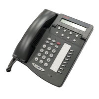
Avaya Definity Callmaster VI Installation And User Manual (21 pages)
Voice Terminal
Brand:
Avaya
| Category:
Telephone
| Size: 0.24 MB
Table of Contents
Important User Safety Instructions
4
Important Safety Warnings for Installation
6
Important Notes on Installation
9
Distance Limitations
9
Checklist of Items
9
Installation Procedures
10
Installation Diagram
11
Connecting the Headsets
14
Using the Buttons
16
Feature Buttons
16
Mute Button
17
Message Waiting Indicator
18
Call Appearance Buttons
18
Release Button
18
Ordering Documentation
19
Advertisement
Related Products
Avaya Definity Callmaster V
Avaya Definity Callmaster II
Avaya Definity Callmaster III
Avaya Definity Callmaster IV
Avaya Definity Callmaster I
Avaya Definity Callmaster
Avaya Desk
Avaya Definity 6408+
Avaya Integral D3
Avaya IP Office D100
Avaya Categories
IP Phone
Telephone
Server
Switch
Gateway
More Avaya Manuals
Login
Sign In
OR
Sign in with Facebook
Sign in with Google
Upload manual
Upload from disk
Upload from URL