
Related Manuals for Intel SR1530HSH - Server System - 0 MB RAM


Summary of Contents for Intel SR1530HSH - Server System - 0 MB RAM
- Page 1 ® Intel Server System SR1530SH/ SR1530HSH User’s Guide ® A Guide for Technically Qualified Assemblers of Intel Identified Subassemblies/ Products Intel Order Number E12554-008...
- Page 2 Intel products are not designed, intended or authorized for use in any medical, life saving, or life sustaining applications or for any other application in which the failure of the Intel product could create a situation where personal injury or death may occur.
-
Page 3: Safety Information
Safety Information Important Safety Instructions Read all caution and safety statements in this document before performing any of the instructions. See also Intel Server Boards and Server Chassis Safety Information on the Server Deployment Toolkit CD and/or at http://www.intel.com/support/ ®... - Page 4 重要安全指导 在执行任何指令之前,请阅读本文档中的所有注意事项及安全声明。 和/或 http://www.intel.com/support/motherboards/server/sb/CS-010770.htm 上的 Intel Server Boards and Server Chassis Safety Information(《Intel 服务器主板与服务器机箱安全信息》)。 ® Intel Server System SR1530SH/SR1530HSH User’s Guide...
-
Page 5: Warnings
Take care to grip with, but not squeeze, the pliers or other tool you use to remove a jumper, or you may bend or break the pins on the board. ® Intel Server System SR1530SH/SR1530HSH User’s Guide... - Page 6 ® Intel Server System SR1530SH/SR1530HSH User’s Guide...
-
Page 7: Preface
BIOS update, and reset the password or CMOS. Information about the ® specific BIOS settings and screens is available in the Intel Server Board S3200SH/ S3210SH Technical Product Specification. See Table 1 for a link to the Technical Product Specification. -
Page 8: Product Contents
Server System SR1530SH/SR1530HSH ships with the Intel Server Board S3200SHL. ® There are two versions of this server system: the Intel Server System SR1530SH and the ® Intel Server System SR1530HSH. The contents of each server system are listed below. -
Page 9: Intel ® Server System Sr1530Hsh Contents
® Intel Server System SR1530HSH Contents ® Your Intel Server System SR1530HSH ships with the following items: ® • One Intel Server Board S3200SHL, installed in the server system • One 350-W power supply module, installed in the server system •... -
Page 10: Server System References
You can find this in the product box. Accessories or other Intel Spares/Parts List and Configuration Guide server products This is available from your Intel field representative or on the Server Configurator Tool at: http://serverconfigurator.intel.com/default.aspx Hardware (peripheral Tested Hardware Operating Systems List (THOL) boards, adapter cards) http://www.intel.com/p/en_US/support/highlights/server/s3200sh... -
Page 11: Table Of Contents
Warnings ..........................v Preface ........................vii About this Manual ........................ vii Manual Organization ......................vii Product Contents .........................viii ® Intel Server System SR1530SH Contents ..............viii ® Intel Server System SR1530HSH Contents ............... ix Server System References ....................x Chapter 1: Server System Features ................1 Chassis Component Identification .................. - Page 12 Installing a PCIe* Riser Card ..................58 Installing and Removing a PCI Add-in Card ................ 59 Installing a PCI Add-in Card ..................59 Removing a PCI Add-in Card ..................60 Replacing the Server Board ....................62 ® Intel Server System SR1530SH / SR1530HSH User’s Guide...
- Page 13 System Boots when Installing PCI Card ..............100 Problems with Newly Installed Application Software ..........100 Problems with Application Software that Ran Correctly Earlier .........100 Devices are not Recognized under Device Manager (Microsoft Windows* Operating Sys- tem) ........................101 ® Intel Server System SR1530SH / SR1530HSH User’s Guide xiii...
- Page 14 Pratiques de manipulation de l’équipement .............. 127 Alimentation et avertissements en matiére d’électricité ..........127 Avertissements sur le cordon d’alimentation ............. 128 Avertissements sur l’accés au systéme ..............128 Avertissements sur le montage en rack ..............129 ® Intel Server System SR1530SH / SR1530HSH User’s Guide...
- Page 15 Regulated Specified Components ................149 Restriction of Hazardous Substances (RoHS) Compliance ..........150 End-of-Life/Product Recycling ...................150 Appendix F: Warranty .................... 151 ® Limited Warranty for Intel Chassis Subassembly Products ..........151 Appendix G: Getting Help ..................155 World Wide Web ........................ 155 Telephone ..........................155 ®...
- Page 16 ® Intel Server System SR1530SH / SR1530HSH User’s Guide...
-
Page 17: List Of Figures
List of Figures ® Figure 1. Intel Server System SR1530SH................1 ® Figure 2. Intel Server System SR1530HSH ................2 Figure 3. Front Controls and LEDs (SR1530SH) ..............5 Figure 4. Front Controls and LEDs (SR1530HSH)..............6 Figure 5. Back Panel Connectors....................7 Figure 6. - Page 18 Figure 78. Installing the Rack Handle ..................85 Figure 79. Removing the Rack Handle ................... 86 Figure 80. Power Cable Routing (SR1530SH) ............... 88 Figure 81. Data Cable Routing (SR1530SH) ................89 Figure 82. Cable Routing (SR1530HSH) ................90 ® xviii Intel Server System SR1530SH/SR1530HSH User’s Guide...
-
Page 19: List Of Tables
List of Tables Table 1. Server System References ..................x ® Table 2. Intel Server System SR1530SH / SR1530HSH Feature Summary ......3 Table 3. NIC1 LED Descriptions ....................7 Table 4. NIC2 LED Descriptions ....................8 Table 5. Setup Menu Key Use ....................16 Table 6. - Page 20 ® Intel Server System SR1530SH/SR1530HSH User’s Guide...
-
Page 21: Chapter 1: Server System Features
® Figure 1. Intel Server System SR1530SH Note: Figure 1 is shown with an optional optical drive installed. -
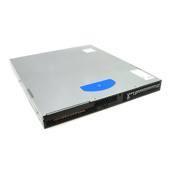
Page 22: Figure 2. Intel ® Server System Sr1530Hsh
® Figure 2. Intel Server System SR1530HSH Note: Figure 2 is shown with an optional optical drive installed. ® Intel Server System SR1530SH/SR1530HSH User’s Guide... - Page 23 Intel Server Board S3200SHL Processor Processor and Front Side Bus (FSB) support • ® ® ® Supports Intel Xeon processor 3000 series and Intel ® ® ® Xeon processor 3100 series, and Intel Xeon processor ® ® 3200 series and Intel...
- Page 24 ® Table 2. Intel Server System SR1530SH / SR1530HSH Feature Summary Feature Description Expansion Capabilities Support for one of the following: • (optional accessory One low-profile riser slot supporting a 1U PCI Express* riser required) card Hard Drives SATA support, 3 Gb/s: capable of supporting up to two drives (SR1530SH) or three drives (SR1530HSH) •...
-
Page 25: Chassis Component Identification
The front of the server system includes the following buttons and LEDs. AF001000 USB Port Hard Disk Drive Activity LED Power Button NIC1 LED System Status LED NIC2 LED System Power LED Figure 3. Front Controls and LEDs (SR1530SH) ® Intel Server System SR1530SH/SR1530HSH User’s Guide... -
Page 26: System Front Panel (Sr1530Hsh)
The front of the server system includes the following buttons and LEDs. AF001573 NIC1 LED HDD Activity LED NIC2 LED USB Port Power LED Power Button System Status LED Figure 4. Front Controls and LEDs (SR1530HSH) ® Intel Server System SR1530SH/SR1530HSH User’s Guide... -
Page 27: System Rear
No network connection Solid Green Network connection in place Blinking Green Transmit/receive activity Right 10 Mbps connection (if left LED is on or blinking) Solid Green 100 Mbps connection Solid Amber 1000 Mbps connection Intel® Server System SR1530SH/SR1530HSH User’s Guide... -
Page 28: Peripheral Devices (Sr1530Sh)
Note: The Intel Server System SR1530SH / SR1530HSH does not support all Serial ATA (SATA) hard drives. See “Server System References” on page x for an Internet link to a list of supported hardware. Intelfi Server System SR1530SH/SR1530HSH User s Guide... -
Page 29: Slimline Optical Drive Carrier
One slimline drive carrier is included with your server system; you must purchase the optical drive separately. To use the slimline DVD drive provided by Intel, use order code AXXSATADVDROM. To use the slimline DVD CDRW drive provided by Intel, use order code AXXSATADVDRWROM. -
Page 30: Internal Components (Sr1530Sh)
System Memory DIMM Sockets Server Board System Blower Fans (two) Processor Air Duct Hard Drive Bays PCIe* Riser Assembly Front Panel Processor and Heat Sink Slimline Optical Drive Bay Figure 6. System Components (SR1530SH) ® Intel Server System SR1530SH/SR1530HSH User’s Guide... -
Page 31: Internal Components (Sr1530Hsh)
System Blower Fans (two) Front Panel Processor Air Duct Hard Drive Carriers (two) Server Board Slimline Optical Drive Bay PCIe* Riser Assembly M. Hard Drive Carrier (one) Processor and Heat Sink Figure 7. System Components (SR1530HSH) ® Intel Server System SR1530SH/SR1530HSH User’s Guide... -
Page 32: Server Board Connectors/Components
SATA 5 AA. SATA 3 BB. Internal USB CC. External USB DD. CMOS Clear Jumper EE. Password Clear Jumper FF. Recovery Mode Jumper GG. Serial Port Figure 8. S3200SH Connector and Component Locations ® Intel Server System SR1530SH/SR1530HSH User’s Guide... -
Page 33: Configuration Jumpers
Jumper in normal position (pins 1-2) allows normal system operation with correct BIOS settings. System will POST normally. ® Jumper in maintenance mode (pins 2-3) allows Intel AMT setting/ password reset. Jumper removed is used to recover from a corrupted BIOS. -
Page 34: Hardware Requirements
For a list of qualified components, see the links under “Server System References”. Processor ® ® ® ® Supports Intel Xeon processor 3000 series and Intel Xeon processor 3100 series, ® ® ® ® and Intel Xeon processor 3200 series and Intel Xeon processor 3300 series. -
Page 35: Chapter 2: Server Utilities
You can run BIOS Setup with or without an operating system ® present. See the links under “Server System References” on page x for a link to the Intel Server Board S3200SH Technical Product Specification where you will find details about specific BIOS setup screens. Starting Setup You can enter and start BIOS Setup under several conditions: •... - Page 36 If “No” is selected and <Enter> is pressed, or <Esc> is pressed, the user is returned to where they were before <F9> was pressed without affecting any existing field values. ® Intel Server System SR1530SH/SR1530HSH User’s Guide...
-
Page 37: Upgrading The Bios
Press <F2> Key if you want to run SETUP 2. Write down the current settings in the BIOS Setup program. Note: Do not skip Step 2. You need these settings to configure your server at the end of the procedure. ® Intel Server System SR1530SH/SR1530HSH User’s Guide... -
Page 38: Upgrading The Bios
Note: You may encounter a CMOS Checksum error or other problem after reboot. If this happens, shut down the system and boot it again. CMOS checksum errors require that you enter Setup, check your settings, save your settings, and exit Setup. ® Intel Server System SR1530SH/SR1530HSH User’s Guide... -
Page 39: Clearing The Cmos
NIC State Diagnostic LEDs Note: Refer to the Technical LAN link is not established. ® ® Not Available on the Intel Server Board S3200SHV. Intel Adaptive Slot 6 functions as either a PCI Express* x16 Product Specification for BIT 2... - Page 40 ® Intel Server System SR1530SH/SR1530HSH User’s Guide...
-
Page 41: Chapter 3: Hardware Installations And Upgrades
Server System SR1530HSH are hot-swappable and are noted as such (where applicable) in the following instructions. ® Note: Most of the illustrations in this chapter show the Intel Server System SR1530SH with an optional optical drive installed. Unless otherwise noted, the instructions for removing and ®... -
Page 42: Removing And Installing The Front Bezel
Removing and Installing the Front Bezel ® The front bezel is available as an optional accessory for the Intel Server System SR1530SH / SR1530HSH. Note the orientation in the following figures and make sure you position your bezel as shown. -
Page 43: Installing The Front Bezel
1. At each end of the bezel, line up the center notch on the bezel with the center guide on the rack handles. 2. Push the bezel onto the front of the server system until it clicks into place. 3. Lock the bezel. AF002317 Figure 12. Installing the Front Bezel ® Intel Server System SR1530SH/SR1530HSH User’s Guide... -
Page 44: Removing And Installing The Server Cover
6. SR1530SH: Push rearward on the blue grip point at the front of the server. Slide the cover back until it stops and then lift the cover upward to remove it. See letter “C” in Figure 13. AF000662 Figure 13. Removing the Server System Cover (SR1530SH) ® Intel Server System SR1530SH/SR1530HSH User’s Guide... -
Page 45: Figure 14. Removing The Server System Cover (Sr1530Hsh)
8. SR1530HSH: Push rearward on the blue grip point at the front of the server. Slide the cover back until it stops and then lift the cover upward to remove it. See letter “B” in Figure 14. AF001578 Figure 14. Removing the Server System Cover (SR1530HSH) ® Intel Server System SR1530SH/SR1530HSH User’s Guide... -
Page 46: Installing The Server System Cover
Slide the cover forward. See letter “A” in Figure 16. 6. SR1530HSH: Install the four screws at the front of the server. See letter “B” in Figure 16. ® Intel Server System SR1530SH/SR1530HSH User’s Guide... -
Page 47: Removing And Installing The Processor Air Duct
3. Remove the server system cover. For instructions, see “Removing the Server System Cover”. 4. Lift the processor air duct from its location behind the two system blower fans (see Figure 17 for SR1530SH; see Figure 18 for SR1530HSH). ® Intel Server System SR1530SH/SR1530HSH User’s Guide... -
Page 48: Figure 17. Removing The Processor Air Duct (Sr1530Sh)
AF002318 Figure 17. Removing the Processor Air Duct (SR1530SH) AF002319 Figure 18. Removing the Processor Air Duct (SR1530HSH) ® Intel Server System SR1530SH/SR1530HSH User’s Guide... -
Page 49: Installing The Processor Air Duct
5. Install the server system cover. For instructions, see “Installing the Server System Cover”. AF002320 Figure 19. Installing the Processor Air Duct (SR1530SH) ® Intel Server System SR1530SH/SR1530HSH User’s Guide... -
Page 50: Installing And Removing Memory
DIMM B2 starting from the center of the board. See “Memory” on page 14 for a discussion of the memory requirements and options. See “Server System References” on page x for a link to the list of tested DIMMs. ® Intel Server System SR1530SH/SR1530HSH User’s Guide... -
Page 51: Installing Dimms
7. Position the DIMM above the socket. Align the notch on the bottom edge of the DIMM with the key in the DIMM socket. See letter “B” in Figure 21. 8. Insert the bottom edge of the DIMM into the socket. See letter “C” in Figure 21. ® Intel Server System SR1530SH/SR1530HSH User’s Guide... -
Page 52: Removing Dimms
6. Holding the DIMM by the edges, lift it from the socket, and store it in an anti-static package. 7. Install the server system cover. For instructions, see “Installing the Server System Cover”. ® Intel Server System SR1530SH/SR1530HSH User’s Guide... -
Page 53: Replacing The Processor
9. Remove the processor. 10. If installing a replacement processor, see “Installing the Processor” on page Otherwise, install the protective socket cover over the empty processor socket and then reinstall the chassis cover. ® Intel Server System SR1530SH/SR1530HSH User’s Guide... -
Page 54: Installing The Processor
5. Push the rear tab with your finger to slightly lift the front of the load plate. Raise the load plate completely. Raise the CPU load plate (see Figure 23). AF000529 Figure 23. Opening the Load Plate Caution: Do not touch the socket pins; they are very sensitive and easily damaged. ® Intel Server System SR1530SH/SR1530HSH User’s Guide... -
Page 55: Figure 24. Removing The Shipping Cover
9. Remove the protective socket cover. See Figure AF000530 Figure 26. Removing the Protective Socket Cover Note: Retain the protective socket cover for use when removing a processor that will not be replaced. ® Intel Server System SR1530SH/SR1530HSH User’s Guide... -
Page 56: Installing The Heat Sink
Figure 27. Do not fully tighten one screw before tightening another. 5. Gradually and equally tighten each captive screw in the same order until each is firmly tightened. AF001049 Figure 27. Installing the Heat Sink ® Intel Server System SR1530SH/SR1530HSH User’s Guide... -
Page 57: Installing And Removing A Hard Drive (Sr1530Sh)
2. Power down the server. Unplug all peripheral devices and the AC power cable. 3. Remove the server system cover. For instructions, see “Removing the Server System Cover” on page 4. Locate the drive position you want to use. See Figure ® Intel Server System SR1530SH/SR1530HSH User’s Guide... -
Page 58: Figure 28. Locating Drive Positions (Sr1530Sh)
Figure 29. Save this screw. You will use it to reinstall the drive assembly later. 7. Lift the drive carrier from the chassis. See letter “B” in Figure 29. AF001050 Figure 29. Removing Drive Carrier from the Server System (SR1530SH) ® Intel Server System SR1530SH/SR1530HSH User’s Guide... -
Page 59: Figure 30. Installing Drive Into Drive Carrier (Sr1530Sh)
“C” in Figure 31. Note: You must install the assembly that contains the optical drive bracket at the left side of the system. AF002323 Figure 31. Install Drive Assembly into the Server System (SR1530SH) ® Intel Server System SR1530SH/SR1530HSH User’s Guide... -
Page 60: Figure 32. Connecting Hard Drive Power And Data Cables (Sr1530Sh)
— Letter “B”: If a drive is installed in the HDD0 carrier, attach the middle connector on the daisy chain power cable to the HDD0 power connector. See letter “D” in Figure AF002324 Figure 32. Connecting Hard Drive Power and Data Cables (SR1530SH) ® Intel Server System SR1530SH/SR1530HSH User’s Guide... -
Page 61: Removing A Hard Disk Drive (Sr1530Sh)
“Installing a Hard Disk Drive (SR1530SH)” on page 37, beginning with step 8. 10. Insert the screws that held the drive in the carrier into the screw locations on the carrier for future use. ® Intel Server System SR1530SH/SR1530HSH User’s Guide... - Page 62 Note: You must install the assembly that contains the optical drive bracket at the left side of the system. 13. Install the server system cover. For instructions, see “Installing the Server System Cover”. ® Intel Server System SR1530SH/SR1530HSH User’s Guide...
-
Page 63: Installing And Removing A Hot-Swap Sata Drive (Sr1530Hsh)
1. If it is installed, remove the front bezel. For instructions, see “Removing the Front Bezel”. 2. Locate the drive position you want to use. See Figure AF002325 Figure 34. Locating Drive Positions (SR1530HSH) ® Intel Server System SR1530SH/SR1530HSH User’s Guide... -
Page 64: Figure 35. Removing The Drive Carrier (Sr1530Hsh)
9. Align the holes in the drive to the holes in the drive carrier and attach it to the carrier with the screws that were attached to the plastic retention device. See letter “B” in Figure 36. AF001584 Figure 36. Installing Drive into Drive Carrier (SR1530HSH) ® Intel Server System SR1530SH/SR1530HSH User’s Guide... -
Page 65: Removing A Hot-Swap Sata Drive (Sr1530Hsh)
7. With the black lever in the fully open position, slide the drive carrier into the server system. The green latch must be to the right. Do not push on the black lever until the lever begins to close by itself. ® Intel Server System SR1530SH/SR1530HSH User’s Guide... -
Page 66: Installing Or Removing A Slimline Optical Drive (Sr1530Sh)
5. Note the orientation of the PCI cooling fan located behind the optical drive bay, then disconnect the fan cable (see letter “A” in Figure 38) and lift the fan from the mounting pegs (see letter “B” in Figure 38). ® Intel Server System SR1530SH/SR1530HSH User’s Guide... -
Page 67: Figure 38. Lifting Pci Cooling Fan From Mounting Pegs (Sr1530Sh)
“A” in Figure 39. You cannot reinstall the knock-out. AF001174 Figure 39. Removing the Knock-out from the Sheet Metal Panel 7. Attach the optical drive to the brackets, using the four screws as shown in Figure ® Intel Server System SR1530SH/SR1530HSH User’s Guide... -
Page 68: Figure 40. Attaching The Optical Drive To The Brackets
10. Connect the mini SATA power connector on the optical drive. 11. Connect the data cable to the optical drive and to the SATA connector on the server board. AF003095 Figure 41. Installing the Optical Drive into the System ® Intel Server System SR1530SH/SR1530HSH User’s Guide... -
Page 69: Removing A Slimline Optical Drive
5. SR1530SH: Note the orientation of the PCI cooling fan located behind the optical drive bay, then disconnect the fan cable (see letter “A” in Figure 43) and lift the fan from the mounting pegs (see letter “B” in Figure 43). ® Intel Server System SR1530SH/SR1530HSH User’s Guide... -
Page 70: Figure 43. Lifting Pci Cooling Fan From Mounting Pegs (Sr1530Sh)
“C” in Figure 44. Save this screw. You will reinstall it later. 8. Slide the optical drive out through the front of the system. See letter “D” in Figure 44. AF000670 Figure 44. Removing the Optical Drive from the Server System ® Intel Server System SR1530SH/SR1530HSH User’s Guide... -
Page 71: Figure 45. Removing The Optical Drive Brackets
46). The fan label should face the rear of the system. Connect the fan cable to the connector on the server board (see letter “B” in Figure 46). AF002328 Figure 46. Installing the PCI Cooling Fan (SR1530SH) ® Intel Server System SR1530SH/SR1530HSH User’s Guide... -
Page 72: Installing Or Removing A Slimline Optical Drive (Sr1530Hsh)
“Removing the Front Bezel” on page 5. First time installation only: Remove the peripheral knock-out by rocking it back and forth. 6. Attach the optical drive attachment bracket as shown in Figure 47. ® Intel Server System SR1530SH/SR1530HSH User’s Guide... -
Page 73: Removing A Slimline Optical Drive (Sr1530Hsh)
1. Observe the safety and ESD precautions at the beginning of this book. See “Safety Information” on page iii. 2. Power down the server and unplug all peripheral devices and the AC power cable. ® Intel Server System SR1530SH/SR1530HSH User’s Guide... -
Page 74: Figure 49. Removing The Optical Drive From The System
Figure 50. Removing the Optical Drive from the Attachment Bracket 7. (Optional) Install the front bezel. For instructions, see “Installing the Front Bezel” on page 8. Install the server system cover. For instructions, see “Installing the Server System Cover”. ® Intel Server System SR1530SH/SR1530HSH User’s Guide... -
Page 75: Installing And Removing The Pcie* Riser Assembly
5. Lift riser assembly up to remove it. Use caution to gently ease the riser card from the add-in card slot so you do not damage the slot or the riser card. See Figure AF002329 Figure 51. Removing PCIe* Riser Assembly from the Server System ® Intel Server System SR1530SH/SR1530HSH User’s Guide... -
Page 76: Installing The Pcie* Riser Assembly
The riser cards will seat into the matching sockets on the server board. 4. Connect any cables to add-in cards that require them. See your add-in card documentation for information and add-in card requirements. ® Intel Server System SR1530SH/SR1530HSH User’s Guide... -
Page 77: Installing Or Replacing A Pcie* Riser Card
7. Remove the two screws that attach the riser card to the riser assembly. See Figure 53. Save these screws to be used later. AF001061 Figure 53. Removing Riser Card from Riser Assembly ® Intel Server System SR1530SH/SR1530HSH User’s Guide... -
Page 78: Installing A Pcie* Riser Card
8. Install an PCI add-in card if desired. For instructions, see “Installing a PCI Add-in Card” on page 9. Install the PCIe* Riser assembly into the server system. For instructions, see “Installing the PCIe* Riser Assembly” on page ® Intel Server System SR1530SH/SR1530HSH User’s Guide... -
Page 79: Installing And Removing A Pci Add-In Card
2. Power down the server and unplug all peripheral devices and the AC power cable. 3. Remove the server system cover. For instructions, see “Removing the Server System Cover” on page 4. Remove the PCIe* Riser assembly. For instructions, see “Removing the PCIe* Riser Assembly” on page ® Intel Server System SR1530SH/SR1530HSH User’s Guide... -
Page 80: Removing A Pci Add-In Card
2. Power down the server and unplug all peripheral devices and the AC power cable. 3. Remove the server system cover. For instructions, see “Removing the Server System Cover” on page 4. Remove the PCIe* Riser assembly. For instructions, see “Removing the PCIe* Riser Assembly” on page ® Intel Server System SR1530SH/SR1530HSH User’s Guide... -
Page 81: Figure 56. Removing A Full Height Add-In Card
“Installing the Processor Air Duct” on page 11. Install the server system cover. For instructions, see “Installing the Server System Cover”. 12. Plug all peripheral devices and the AC power cable into the server. ® Intel Server System SR1530SH/SR1530HSH User’s Guide... -
Page 82: Replacing The Server Board
6. Detach all cables connected to the server board. 7. Remove the heat sink and the processor. For instructions, see “Removing the Heat Sink and Processor” on page 8. Remove the DIMMs. For instructions, see “Removing DIMMs” on page ® Intel Server System SR1530SH/SR1530HSH User’s Guide... -
Page 83: Figure 57. Removing The Server Board
Figure 80 on page 15. Install the processor air duct. For instructions, see “Installing the Processor Air Duct” on page 16. Install the server system cover. For instructions, see “Installing the Server System Cover”. ® Intel Server System SR1530SH/SR1530HSH User’s Guide... -
Page 84: Installing The Server Board
6. Place the server board into the server system as shown by letter “A” in Figure 58. 7. Attach the server board with nine screws. See letter “B” in Figure 58. AF002332 Figure 58. Installing the Server Board ® Intel Server System SR1530SH/SR1530HSH User’s Guide... -
Page 85: Replacing The Cmos Battery
Varning: Explosionsfara vid felaktigt batteribyte. Använd samma batterityp eller en ekvivalent typ som rekommenderas av apparattillverkaren. Kassera använt batteri enligt fabrikantens instruktion. Varoitus: Paristo voi räjähtää, jos se on virheellisesti asennettu. Vaihda paristo ainoastaan laitevalmistajan suosittelemaan tyyppiin. Hävitä käytetty paristo valmistajan ohjeiden mukaisesti. ® Intel Server System SR1530SH/SR1530HSH User’s Guide... -
Page 86: Figure 59. Replacing The Cmos Battery
8. Remove the new lithium battery from its package, and, being careful to observe the correct polarity, insert it in the battery socket. 9. Close the chassis. 10. Run the BIOS Setup utility to restore the configuration settings. ® Intel Server System SR1530SH/SR1530HSH User’s Guide... -
Page 87: Replacing The Power Supply (Sr1530Sh)
— C: Daisy-chain cable to: Optical drive power connector, if an optical drive is installed HDD0 power connector, if a hard drive is installed here HDD1 power connector, if a hard drive is installed here ® Intel Server System SR1530SH/SR1530HSH User’s Guide... -
Page 88: Figure 60. Disconnecting Power Cables (Sr1530Sh)
AF002473 Figure 60. Disconnecting Power Cables (SR1530SH) ® Intel Server System SR1530SH/SR1530HSH User’s Guide... -
Page 89: Figure 61. Removing Power Supply From The Server System (Sr1530Sh)
See letter “B” in Figure 61. 7. Slide the power supply forward (see letter “C”) and then lift it from the chassis. AF002474 Figure 61. Removing Power Supply from the Server System (SR1530SH) ® Intel Server System SR1530SH/SR1530HSH User’s Guide... -
Page 90: Figure 62. Installing Power Supply Module Into The Server System (Sr1530Sh)
10. Insert the screw you removed in Step 5 to attach the power supply to the server system. See letter “C” in Figure 62. AF002475 Figure 62. Installing Power Supply Module into the Server System (SR1530SH) ® Intel Server System SR1530SH/SR1530HSH User’s Guide... -
Page 91: Figure 63. Connecting Power Cables (Sr1530Sh)
Figure 63. Connecting Power Cables (SR1530SH) 12. Install the server system cover. For instructions, see “Installing the Server System Cover”. 13. Plug all peripheral devices and the AC power cable into the server. ® Intel Server System SR1530SH/SR1530HSH User’s Guide... -
Page 92: Replacing The Power Supply (Sr1530Hsh)
(see letter “B” in Figure 64). 6. Slide the power supply forward (see letter “C” in Figure 64) and then lift it from the chassis. AF002477 Figure 64. Removing Power Supply from the Server System (SR1530HSH) ® Intel Server System SR1530SH/SR1530HSH User’s Guide... -
Page 93: Figure 65. Installing Power Supply Module Into The Server System (Sr1530Hsh)
10. Install the server system cover. For instructions, see “Installing the Server System Cover”. 11. Plug all peripheral devices and the AC power cable into the server (see letter “C” in Figure 65). ® Intel Server System SR1530SH/SR1530HSH User’s Guide... -
Page 94: Replacing The Front Panel Board (Sr1530Sh)
“D” in Figure 66. Save these screws. You will re-install them later. 7. Lift the front panel board from the system. See letter “E” in Figure 66. AF002479 Figure 66. Removing Front Panel Board from the Server System (SR1530SH) ® Intel Server System SR1530SH/SR1530HSH User’s Guide... -
Page 95: Figure 67. Installing Front Panel Board Into The Server System (Sr1530Sh)
Figure 67. Installing Front Panel Board into the Server System (SR1530SH) 13. Install the server system cover. For instructions, see “Installing the Server System Cover”. 14. Plug all peripheral devices and the AC power cable into the server. ® Intel Server System SR1530SH/SR1530HSH User’s Guide... -
Page 96: Replacing The Front Panel Board (Sr1530Hsh)
6. Slide the front panel board back (see letter “B” in Figure 68) and lift the front panel board from the system (see letter “C” in Figure 68). AF001589 Figure 68. Removing Front Panel Board from the Server System (SR1530HSH) ® Intel Server System SR1530SH/SR1530HSH User’s Guide... -
Page 97: Figure 69. Removing Light Pipes From The Front Panel Board (Sr1530Hsh)
9. Use the screw you removed in Step 5 to attach the front panel board to the system (see letter “C” in Figure 70). AF001590 Figure 70. Installing Front Panel Board into the Server System (SR1530HSH) ® Intel Server System SR1530SH/SR1530HSH User’s Guide... -
Page 98: Figure 71. Installing Light Pipes On The Front Panel Board (Sr1530Hsh)
12. Connect the front panel cable. 13. Install the server system cover. For instructions, see “Installing the Server System Cover”. 14. Plug all peripheral devices and the AC power cable into the server. ® Intel Server System SR1530SH/SR1530HSH User’s Guide... -
Page 99: Replacing A System Fan (Sr1530Sh)
5. Disconnect the two fan cables from the server board (see letter “B” in Figure 72) and untie the cable tie (see letter “C” in Figure 72). AF002481 Figure 72. Disconnecting System Blower Fans (SR1530SH) ® Intel Server System SR1530SH/SR1530HSH User’s Guide... -
Page 100: Figure 73. Removing Bracket And System Blower Fans From Server System (Sr1530Sh)
8. Lift the fan bracket from the server. Lift the bracket at an angle, front of the bracket first, to clear the hard disk drive brackets. See letter “C” in Figure 73. AF002482 Figure 73. Removing Bracket and System Blower Fans from Server System (SR1530SH) ® Intel Server System SR1530SH/SR1530HSH User’s Guide... -
Page 101: Figure 74. Removing Fan From Fan Bracket (Sr1530Sh)
13. Route the cable from the fan at the right around the right side of the assembly and under the clip at the front of the fan bracket. ® Intel Server System SR1530SH/SR1530HSH User’s Guide... -
Page 102: Figure 75. Connecting System Blower Fans (Sr1530Sh)
14. Connect the fans to the server board. See letters “A” and “B” in Figure 75. AF002483 Figure 75. Connecting System Blower Fans (SR1530SH) 15. Install the processor air duct. For instructions. see “Installing the Processor Air Duct” on page ® Intel Server System SR1530SH/SR1530HSH User’s Guide... -
Page 103: Replacing A System Fan (Sr1530Hsh)
5. Remove the two screws that hold the fan in place. Save these screws. You will re- install them later. 6. Disconnect the fan cable from the server board (see letter “B” in Figure 76). ® Intel Server System SR1530SH/SR1530HSH User’s Guide... -
Page 104: Figure 76. Removing Fan From The Server System (Sr1530Hsh)
Figure 77. Installing Fan into the Server System (SR1530HSH) 11. Install the server system cover. For instructions, see “Installing the Server System Cover”. 12. Plug all peripheral devices and the AC power cable into the server. ® Intel Server System SR1530SH/SR1530HSH User’s Guide... -
Page 105: Installing And Removing The Rack Handles
5. Repeat Step 4 on the opposite side of the server. 6. (Optional) Install the front bezel, if desired. For instructions, see “Installing the Front Bezel” on page 7. Plug all peripheral devices and the AC power cable into the server. ® Intel Server System SR1530SH/SR1530HSH User’s Guide... -
Page 106: Removing The Rack Handles
5. Repeat Step 4 on the opposite side of the system. 6. (Optional) Install the front bezel, if desired. For instructions, see “Installing the Front Bezel” on page 7. Plug all peripheral devices and the AC power cable into the server. ® Intel Server System SR1530SH/SR1530HSH User’s Guide... -
Page 107: Appendix A: Technical Reference
For example, the PCI cooling fan cable is labeled with the letter “C” both where it connects to the server board and at the PCI cooling fan itself. ® Intel Server System SR1530SH/SR1530HSH User’s Guide... -
Page 108: Power Cable Routing (Sr1530Sh)
Note: The power cable to the two hard drives and the optical drive is a single daisy chain cable. To make Figure 80 more clear, where the connectors attach to the components, the labels “F1”, “F2”, and “F3” are used. The end at the power supply itself is labeled “F”. ® Intel Server System SR1530SH/SR1530HSH User’s Guide... -
Page 109: Data Cable Routing (Sr1530Sh)
Data Cable Routing (SR1530SH) AF002485 Front panel USB SATA 0 to HDD0 Front panel Optical drive SATA 1 to HDD1 Figure 81. Data Cable Routing (SR1530SH) ® Intel Server System SR1530SH/SR1530HSH User’s Guide... -
Page 110: Cable Routing (Sr1530Hsh)
HDD 0 to Server Board SATA 2 HDD 1 to Server Board SATA 3 HDD 2 to Server Board SATA 4 Optical Drive to Server Board SATA 0 AF002486 Figure 82. Cable Routing (SR1530HSH) ® Intel Server System SR1530SH/SR1530HSH User’s Guide... -
Page 111: 350-W Single Power Supply Input Voltages
Warning: Do not exceed a combined power output of 90 W for the +5 V and +3.3 V outputs. Exceeding a combined 90 W will overload the power subsystem and may cause the power supplies to overheat and malfunction. ® Intel Server System SR1530SH/SR1530HSH User’s Guide... -
Page 112: System Environmental Specifications
7 Bels in sound power for a typical office ambient temperature (65 to 75 °F). Your selection of peripherals may change the noise level. Electrostatic Tested to 15 kilovolts (kV); no component damage. discharge (ESD) ® Intel Server System SR1530SH/SR1530HSH User’s Guide... -
Page 113: Appendix B: Troubleshooting
In addition to the server firmware and files, also update any drivers used for components you installed in your system, such as video drivers, network drivers, and SATA drivers. Intel provides a package called the “Platform Confidence Test” that may help with your diagnostics. See “Server System References” on page x for a link to this software. -
Page 114: Problems Following Initial System Installation
• Are all integrated components from the tested components lists? Check the tested memory and chassis lists, as well as the supported hardware and operating system list. See “Server System References” on page x for links to the tested component lists. ® Intel Server System SR1530SH/SR1530HSH User’s Guide... -
Page 115: Hardware Diagnostic Testing
“No Characters Appear on Screen” on page Specific Problems and Corrective Actions This section provides possible solutions for these specific problems: • Power light does not light. • No characters appear on screen. ® Intel Server System SR1530SH/SR1530HSH User’s Guide... -
Page 116: Power Light Does Not Light
No Characters Appear on Screen Check the following: • Is the keyboard functioning? Test it by turning the “Num Lock” function on and off to make sure the Num Lock light is functioning. ® Intel Server System SR1530SH/SR1530HSH User’s Guide... -
Page 117: Characters Are Distorted Or Incorrect
• Does this video monitor work correctly if plugged into a different system? System Cooling Fans Do Not Rotate Properly If the system cooling fans are not operating properly, it is an indication of possible system component failure. ® Intel Server System SR1530SH/SR1530HSH User’s Guide... -
Page 118: Drive Activity Light Does Not Light
• Try a different network cable. • Make sure you are using the correct and the current drivers. See “Server System References” on page x for a link to the current drivers. ® Intel Server System SR1530SH/SR1530HSH User’s Guide... -
Page 119: Problems With Network
• Try reseating the add-in adapter. The add-in adapter stopped working without apparent cause • Reseat the adapter. • The network driver files may be corrupt or deleted. Delete and then reinstall the drivers. • Run diagnostics. ® Intel Server System SR1530SH/SR1530HSH User’s Guide... -
Page 120: System Boots When Installing Pci Card
• If you suspect a transient voltage spike, power outage, or brownout might have occurred, reload the software and try running it again. Symptoms of voltage spikes ® Intel Server System SR1530SH/SR1530HSH User’s Guide... -
Page 121: Devices Are Not Recognized Under Device Manager (Microsoft Windows* Operating System)
Devices are not Recognized under Device Manager (Microsoft Windows* Operating System) ® The Microsoft Windows* operating systems do not include all of the drivers for the Intel chipsets, onboard NICs, and other components. See “Server System References” on page x for a link to the current drivers and chipset files. -
Page 122: Led Information
LED Information ® The Intel Server System SR1530AH / SR1530AHLX / SR1530HAHLX includes LEDs that can aid in troubleshooting your system. Table 8 lists these LEDs and provides a description of their use. Table 8. LED Information LED Name Function... -
Page 123: Appendix C: Installation/Assembly Safety Instructions
5. Provide some electrostatic discharge (ESD) protection by wearing an antistatic wrist strap attached to chassis ground of the system-any unpainted metal surface-when handling components. 6. Do not operate the system with the chassis covers removed. ® Intel Server System SR1530SH/SR1530HSH User’s Guide... - Page 124 • Provided with a properly grounded wall outlet. • Provided with sufficient space to access the power supply cord(s), because they serve as the product's main power disconnect. ® Intel Server System SR1530SH/SR1530HSH User’s Guide...
-
Page 125: Deutsch
Anschlußkabel von den I/O Anschlüssen oder Ports ab. 5. Tragen Sie ein geerdetes Antistatik Gelenkband, um elektrostatische Ladungen (ESD) über blanke Metallstellen bei der Handhabung der Komponenten zu vermeiden. 6. Schalten Sie das System niemals ohne ordnungsgemäß montiertes Gehäuse ein. ® Intel Server System SR1530SH/SR1530HSH User’s Guide... - Page 126 Schutzhandschuhe tragen. Bei falschem Einsetzen einer neuen Batterie besteht Explosionsgefahr. Die Batterie darf nur durch denselben oder einen entsprechenden, vom Hersteller empfohlenen Batterietyp ersetzt werden. Entsorgen Sie verbrauchte Batterien den Anweisungen des Herstellers entsprechend. ® Intel Server System SR1530SH/SR1530HSH User’s Guide...
-
Page 127: Français
Notez que le commutateur CC de mise sous tension /hors tension du panneau avant n'éteint pas l'alimentation CA du système. Pour mettre le système hors tension, vous devez débrancher chaque câble d'alimentation de sa prise. ® Intel Server System SR1530SH/SR1530HSH User’s Guide... - Page 128 Le microprocesseur et le dissipateur de chaleur peuvent être chauds si le système a été sous tension. Faites également attention aux broches aiguës des cartes et aux bords tranchants du capot. Nous vous recommandons l'usage de gants de protection. ® Intel Server System SR1530SH/SR1530HSH User’s Guide...
-
Page 129: Español
No intente modificar ni usar el cable de alimentación de corriente alterna, si no corresponde exactamente con el tipo requerido. El número de cables suministrados se corresponden con el número de fuentes de alimentación de corriente alterna que tenga el producto ® Intel Server System SR1530SH/SR1530HSH User’s Guide... - Page 130 4. Inserte el bloqueo de seguridad en el sistema y bloquéelo para impedir que pueda accederse al mismo sin autorización. 5. Conecte todos los cables externos y los cables de alimentación CA al sistema. ® Intel Server System SR1530SH/SR1530HSH User’s Guide...
- Page 131 • "Provisto de una toma de tierra correctamente instalada. • "Provisto de espacio suficiente como para acceder a los cables de alimentación, ya que éstos hacen de medio principal de desconexión del sistema. ® Intel Server System SR1530SH/SR1530HSH User’s Guide...
-
Page 132: Italiano
1. Aprire e rimuovere il lucchetto dal retro del sistema qualora ve ne fosse uno installato. 2. Togliere e mettere in un posto sicuro tutte le viti delle coperture. 3. Togliere le coperture. ® Intel Server System SR1530SH/SR1530HSH User’s Guide... - Page 133 • "Dotata di una presa a muro correttamente installata. • "Dotata di spazio sufficiente ad accedere ai cavi di alimentazione, i quali rappresentano il mezzo principale di scollegamento del sistema. ® Intel Server System SR1530SH/SR1530HSH User’s Guide...
- Page 134 ® Intel Server System SR1530SH/SR1530HSH User’s Guide...
-
Page 135: Appendix D: Safety Information
To reduce the risk of bodily injury, electrical shock, fire, and equipment damage, read this document and observe all warnings and precautions in ® this guide before installing or maintaining your Intel server product. In the event of a conflict between the information in this document and information provided with the product or on the website for a particular product, the product documentation takes precedence. -
Page 136: Intended Application Uses
Conform to local occupational health and safety requirements when moving and lifting equipment. • Use mechanical assistance or other suitable assistance when moving and lifting equipment. • To reduce the weight for easier handling, remove any easily detachable components. ® Intel Server System SR1530SH/SR1530HSH User’s Guide... -
Page 137: Power And Electrical Warnings
Do not attempt to modify or use an AC power cord if it is not the exact type required. A separate AC cord is required for each system power supply. ® Some power supplies in Intel servers use Neutral Pole Fusing. To avoid risk of shock use caution when working with power supplies that use Neutral Pole Fusing. -
Page 138: System Access Warnings
To avoid risk of potential electric shock, a proper safety ground must be implemented for the rack and each piece of equipment installed in it. ® Intel Server System SR1530SH/SR1530HSH User’s Guide... -
Page 139: Electrostatic Discharge (Esd)
Caution: To avoid risk of radiation exposure and/or personal injury: • Do not open the enclosure of any laser peripheral or device. • Laser peripherals or devices have are not user serviceable. • Return to manufacturer for servicing. ® Intel Server System SR1530SH/SR1530HSH User’s Guide... -
Page 140: Deutsch
Deutsch Sicherheitshinweise für den Server ® ® Das vorliegende Dokument bezieht sich auf Intel Serverplatinen, Intel Servergehäuse (Standfuß und Rack) sowie installierte Peripheriegeräte. Es enthält Warnungen und Vorsichtsmaßnahmen zur Vermeidung von Gefahren durch Verletzung, Stromschlag, Feuer und Beschädigungen von Geräten. Lesen Sie diese Dokument daher sorgfältig, ®... -
Page 141: Zielbenutzer Der Anwendung
Verwenden Sie mechanische oder andere geeignete Hilfsmittel zum Transportieren oder Anheben von Geräten. • Entfernen Sie alle Komponenten, die sich leicht abnehmen lassen, um das Gewicht zu reduzieren und die Handhabung zu erleichtern. ® Intel Server System SR1530SH/SR1530HSH User’s Guide... -
Page 142: Warnungen Zu Netzspannung Und Elektrizität
Typ entspricht. Jedes Netzteil im System muß über ein eigenes Netzkabel angeschlossen werden. Einige Netzteile von Intel Servern verwenden Nullleitersicherungen. Vorsicht ist geboten im Umgang mit Netzteilen, welche Nullleitersicherungen verwenden, um das Risiko eines elektrischen Schlages zu vermeiden Das Netzteil in diesem Produkt enthält keine Teile, die vom Benutzer gewartet werden... -
Page 143: Warnhinweise Für Den Systemzugang
Gehen Sie bei der Installation von Geräten im Rack immer von unten nach oben vor, und bauen Sie das schwerste Gerät an der untersten Position im Rack ein. Ziehen Sie jeweils immer nur ein Gerät aus dem Rack heraus. ® Intel Server System SR1530SH/SR1530HSH User’s Guide... -
Page 144: Elektrostatische Entladungen (Esd)
Inbetriebnahme des Systems ohne Abdeckung kann zur Beschädigung von Systemkomponenten führen. So bringen Sie die Abdeckung wieder an: • Vergewissern Sie sich zunächst, daß Sie keine Werkzeuge oder Teile im Gehäuse vergessen haben. ® Intel Server System SR1530SH/SR1530HSH User’s Guide... -
Page 145: Français
® d’installer ou de mettre à jour votre produit serveur Intel En cas de conflit entre les informations fournies dans ce document et celles livrées avec le produit ou publiées sur le site Web pour un produit particulier, la documentation du produit prime. -
Page 146: Domaines D'utilisation Prévus
Bien ventilé et à l’écart des sources de chaleur telles que la lumière directe du soleil et les radiateurs. • À l’écart des sources de vibration ou des chocs physiques. • Isolé des champs électromagnétiques importants produits par des appareils électriques. ® Intel Server System SR1530SH/SR1530HSH User’s Guide... -
Page 147: Pratiques De Manipulation De L'équipement
Vous devez les débrancher avant d’ouvrir le châssis, d’ajouter ou de supprimer un composant non connectable à chaud. Les alimentations de certains serveurs Intel sont munies de doubles fusibles pôle/neutre: veuillez observer les précautions d'usage afin d'éviter tout risque d'eléctrocution. -
Page 148: Avertissements Sur Le Cordon D'alimentation
Éteignez le système en appuyant sur le bouton d’alimentation. • Déconnectez l’alimentation secteur en débranchant tous les cordons d’alimentation secteur du système ou de la prise murale. • Déconnectez l’ensemble des câbles et lignes de télécommunication qui sont connectés au système. ® Intel Server System SR1530SH/SR1530HSH User’s Guide... -
Page 149: Avertissements Sur Le Montage En Rack
étiqueté comme contrôlant toute l’unité, et pas uniquement le ou les serveurs. Pour éviter tout risque d’électrocution, le rack et chaque élément de l’équipement installé dans le rack doivent être correctement reliés à la terre. ® Intel Server System SR1530SH/SR1530HSH User’s Guide... -
Page 150: Décharges Électrostatiques (Esd)
Vérifiez tout d’abord que vous n’avez pas oublié d’outils ou de composants détachés à l’intérieur du système. • Vérifiez que les câbles, les cartes d’extension et les autres composants sont correctement installés. • Fixez les panneaux au châssis en suivant les instructions du produit. ® Intel Server System SR1530SH/SR1530HSH User’s Guide... -
Page 151: Périphériques Laser
Retournez-les au fabricant en cas de problème. Español Información de seguridad del servidor ® Este documento se aplica a las tarjetas de servidor de Intel , las carcasas de servidor de ® Intel (montaje en bastidor y en pedestal) y los dispositivos periféricos. Para reducir el riesgo de daños corporales, descargas eléctricas, fuego y en el equipo, lea este documento... -
Page 152: Aplicaciones Y Usos Previstos
Provista de una toma de corriente alterna correctamente conectada a tierra. • Provista de espacio suficiente para acceder a los cables de la fuente de alimentación ya que constituyen la desconexión principal de la alimentación. ® Intel Server System SR1530SH/SR1530HSH User’s Guide... -
Page 153: Manipulacién Del Equipo
CA estén desenchufado antes de abrir la carcasa, agregar o extraer cualquier componente que no es de conexión en funcionamiento. Algunas fuentes de alimentación de electricidad de los servidores de Intel utilizan el polo neutral del fuselaje. Para evitar riesgos de choques electricos use precauciónes al trabajar con las fuentes de alimentación que utilizan el polo neutral de fuselaje. -
Page 154: Advertencias El Acceso Al Sistema
Devuélvala al fabricante para repararla. • Apague el servidor y desconecte todos los cables de alimentación antes de agregar o reemplazar cualquier componente que no es de conexión en funcionamiento. ® Intel Server System SR1530SH/SR1530HSH User’s Guide... - Page 155 Para que no llegue a tocar los componentes que estén calientes cuando esté realizando una instalación de conexión en funcionamiento, tenga cuidado al extraer o instalar los componentes de conexión en funcionamiento. ® Intel Server System SR1530SH/SR1530HSH User’s Guide...
-
Page 156: Advertencias Sobre El Montaje En Bastidor
Sujételas sólo por los bordes. Una vez extraída la tarjeta de su envoltorio de protección o del servidor, colóquela con el lado de los componentes hacia arriba sobre una superficie con toma de tierra y sin carga estática. Utilice una ® Intel Server System SR1530SH/SR1530HSH User’s Guide... -
Page 157: Otros Riesgos
Precaución Para evitar el riesgo de la exposición a radiaciones o de daños personales: • No abra la caja de ningún periférico o dispositivo láser • Los periféricos o dispositivos láser no pueden ser reparados por el usuario • Haga que el fabricante los repare ® Intel Server System SR1530SH/SR1530HSH User’s Guide... - Page 158 服 务器 机箱 (基 座和 机架 固定 件) 和已 安装 的外 设。 为减 少人 身伤 害、 电 击、 火灾 以及 设备 毁坏 的危 险, 请在 安装 或维 护 Intel® 服 务器 产品 之前 阅读 本文 档并 遵循 本指 南中 的所 有警 告和 预防 措施 。...
- Page 159 • 远离振动源或物理震动。 • 与电气设备产生的强大电磁场隔离。 • 在易受闪电袭击的地区,我们建议将系统插入电涌抑制器并在闪电期间断开通信 线路与调制解调器之间的连接。 • 提供正确接地的墙壁插座。 • 提供足够的空间,以便拿取电源供应线,因为这是本产品的主要电源断开器。 设备操作规范 减少人身伤害或设备受损的危险: • 移举设备时遵守当地的职业健康与安全要求。 • 借助机械手段或其他合适的手段移举设备。 • 拆除一切易分离组件,以降低重量并方便操作。 电源与电气警告 注意事项 电源按钮(如待机电源标记所示)并不能完全关闭系统的交流电源,只要系统已接 通电源,就存在 5V 待机电源。要从系统切断电源,须从墙壁电源插座中拔下交流电线。您的系统可能 不止使用一根交流电线。请确保所有的交流电线都已拔下。打开机箱或增加或去除 任何热插拔组件之前,确保交流电线已拔下。 若非所需的确切类型,请勿尝试修改或使用交流电线。系统的每个电源供应设备都 需要一根单独的交流电线。 本产品的电源供应设备包含非用户维修部件。请勿打开电源供应设备。电源供应设 备包含非常危险的电压级、电流级和能量级。请与生产商联系维修事宜。 替换热插拔电源供应设备时,请先拔下需替换的电源供应设备上的电源线,再将其 从服务器上移除。 ® Intel Server System SR1530SH/SR1530HSH User’s Guide...
- Page 160 ⎯ 电源线须拥有适合插座的安全接地插头或触点。 • 电源线为交流电源的主要断开设备。插座须靠近设备并可随时断开。 • 电源线须插入所提供的拥有合适接地的插座。 系统使用警告 注意事项 为避免人身伤害或财产损失,无论何时检查产品内部,以下安全指导都适用: • 关闭所有与本产品相连的外设。 • 按下电源按钮至关闭状态,关闭系统。 • 从系统或墙壁插座上拔下所有交流电线,断开交流电源。 • 断开与系统相连的所有线缆和通信线路。 • 卸除舱口盖时,保留所有螺钉及其他紧固件。完成产品内部检查之后,请 用螺钉或紧固件重新固定舱口盖。 • 请勿打开电源供应设备。电源供应设备内没有可维修部件。请与生产商联系 维修事宜. • 增加或替换任何非热插拔组件之前,请关闭服务器电源并断开所有电源线 。 • 替换热插拔电源供应设备时,请先拔下需替换的电源供应设备上的电源线 ,然后再从服务器上移除电源供应设备。 注意事项 如果服务器一直在运行,任何已安装的处理器和吸热设备都可能很热。除非要增加 或移除热插拔组件,否则请待系统冷却后再开盖。为避免在热插拔组件安装过程中 接触灼热组件,移除或安装热插拔组件时务须小心。 ® Intel Server System SR1530SH/SR1530HSH User’s Guide...
- Page 161 注意事项 为避免受伤,请勿触摸运转的风机叶片。如果系统的风机上配有防护装置,请勿卸 下风机防护装置运行系统。 机架固定件警告 设备的机架须固定在稳固的支座上,以防从中安装服务器或设备时倒塌。须按照机 架生产商提供的安装说明进行安装。 从下往上将设备安装在机架上,最重的设备安装在机架的最底层。 一次只从机架上安装一件设备。 您须负责安装整个机架装置的主要电源断开设备。此主要断开设备须随时可用,且 须标明为控制整个装置(而不仅限于服务器)的电源。 为避免潜在的电击危险,须对机架及其上所安装的每一件设备实行正确的安全接地 。 静电放电 (ESD) 注意事项 ESD 会损坏磁盘驱动器、主板及其他部件。我们建议您执行 ESD 工作站的所有步骤。如果没有 ESD 工作站,则采取一些静电放电保护措施,操作部件时,戴上与服务器上的机箱接地 或任何未喷漆金属表面连接的防静电腕带。 操作主板时始终保持小心。它们可能对 ESD 非常敏感。拿持主板时只接触边缘。从保护包装中或从服务器上取出主板后,请将 主板组件侧面朝上放置在无静电的接地表面上。请使用导电泡沫垫(若有),不要 使用主板包装。请勿将主板在任何表面上滑动。 ® Intel Server System SR1530SH/SR1530HSH User’s Guide...
- Page 162 其他危险 替换电池 注意事项 不正确替换电池可能导致爆炸危险。替换电池时,请只使用设备生产商推荐使用的 电池。 请按当地法规处置电池。 请勿对电池充电。 请勿拆卸、刺穿或以其他方式损坏电池。 冷却和气流 注意事项 按照说明小心布置线缆,尽量减少气流阻塞和冷却问题。 为保证适当的冷却和气流,运行系统时请确保机箱盖已安装。未安装机箱盖即运行 系统可能导致系统部件受损。安装机箱盖的步骤如下: 首先检查并确保系统内没有遗留的未固定工具或部件。 • 检查线缆、内插板和其他组件已正确安装。 • 按产品说明安装机箱盖。 • 激光外设或激光设备 注意事项 为避免幅射暴露和 / 或人身伤害: 请勿打开任何激光外设或激光设备的外壳 • 激光外设或激光设备为非用户维修设备 • 请与生产商联系维修事宜 ® Intel Server System SR1530SH/SR1530HSH User’s Guide...
-
Page 163: Appendix E: Regulatory And Compliance Information
(or higher) and operating at the same (or higher) speed as the microprocessor used on this server board. The final configuration of your end system product may require additional EMC compliance testing. For more information, please contact your local Intel representative. -
Page 164: Product Emc Compliance - Class A Compliance
This server system has been tested and verified to comply with the following ® electromagnetic compatibility (EMC) regulations when installed in a compatible Intel host system. For information on compatible host system(s) refer to Intel's Server Builder Web site or contact your local Intel representative. •... -
Page 165: Certifications/Registrations/Declarations
RRL Certification (Korea) • IRAM Certification (Argentina) • Ecology Declaration (International) Product Regulatory Compliance Markings ® This Intel server system product is provided with the following regulatory marks. Table 10. Product Regulatory Compliance Markings Regulatory Compliance Region Marking cULus Listing Marks... - Page 166 Table 10. Product Regulatory Compliance Markings Regulatory Compliance Region Marking C-Tick Mark Australia/New Zealand VCCI Marking (Class A) Japan BSMI Certification Taiwan Number & Class A Warning GOST R Marking Russia RRL MIC Mark Korea ® Intel Server System SR1530SH/SR1530HSH User’s Guide...
-
Page 167: Electromagnetic Compatibility Notices
(1) this device may not cause harmful interference, and (2) this device must accept any interference received, including interference that may cause undesired operation. For questions related to the EMC performance of this product, contact: Intel Corporation 5200 N.E. Elam Young Parkway Hillsboro, OR 97124-6497 1-800-628-8686 This equipment has been tested and found to comply with the limits for a Class A digital device, pursuant to Part 15 of the FCC Rules. -
Page 168: Industry Canada (Ices-003)
Install and use the equipment according to the instruction manual. BSMI (Taiwan) The BSMI Certification Marking and EMC warning is located on the outside rear area of the product. ® Intel Server System SR1530SH/SR1530HSH User’s Guide... -
Page 169: Korean Compliance (Rrl)
Updated product information for configurations can be found on the Intel Server Builder Web site at the following URL: http://channel.intel.com/go/serverbuilder If you do not have access to Intel's Web address, please contact your local Intel representative. •... -
Page 170: Restriction Of Hazardous Substances (Rohs) Compliance
Restriction of Hazardous Substances (RoHS) Compliance Intel has a system in place to restrict the use of banned substances in accordance with the European Directive 2002/95/EC. Compliance is based on declaration that materials banned in the RoHS Directive are either (1) below all applicable substance threshold limits or (2) an approved/pending RoHS exemption applies. -
Page 171: Appendix F: Warranty
"as is" unless specifically provided for otherwise in any software license accompanying the software. If any Product furnished by Intel which is the subject of this Limited Warranty fails during the warranty period for reasons covered by this Limited Warranty, Intel, at its option, will: •... -
Page 172: Warranty Limitations And Exclusions
Limitations of Liability Intel's responsibility under this, or any other warranty, implied or expressed, is limited to repair, replacement, or refund, as set forth above. These remedies are the sole and exclusive remedies for any breach of warranty. -
Page 173: How To Obtain Warranty Service
Telephone Support If you cannot find the information you need on Intel's World Wide Web site (http:// www.intel.com/), call your local distributor or an Intel Customer Support representative. - Page 174 ® Intel Server System SR1530SH/SR1530HSH User’s Guide...
-
Page 175: Appendix G: Getting Help
Telephone All calls are billed per incident, levied in local currency at the applicable credit card exchange rate plus applicable taxes. (Intel reserves the right to change the pricing for telephone support at any time without notice). ® Before calling, fill out an Intel Server Issue Report Form. -
Page 176: Latin America
Easter Island....Contact AT&T USA at 800 800 311. Once connected, dial 800 843 4481 Mainland and Juan .. Contact AT&T USA at 800 225 288. Once connected, dial 800 843 4481 ® Intel Server System SR1530SH/SR1530HSH User’s Guide... - Page 177 Panama..Contact AT&T USA at 00 800 001 0109. Once connected, dial 800 843 4481 Paraguay ... 001 916 377 0114 Peru ... 001 916 377 0114 Uruguay..001 916 377 0114 Venezuela... Contact AT&T USA at 0 800 2255 288. Once connected, dial 800 843 4481 ® Intel Server System SR1530SH/SR1530HSH User’s Guide...
- Page 178 ® Intel Server System SR1530SH/SR1530HSH User’s Guide...